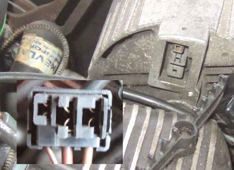
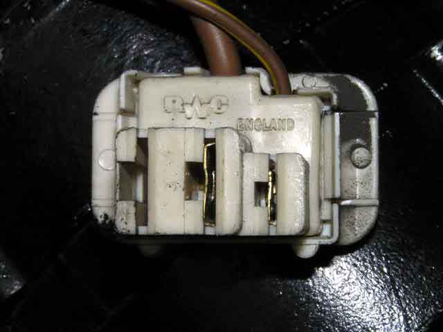
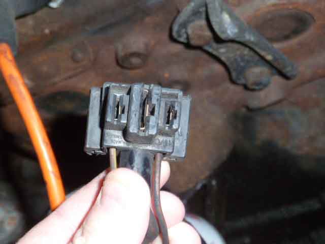
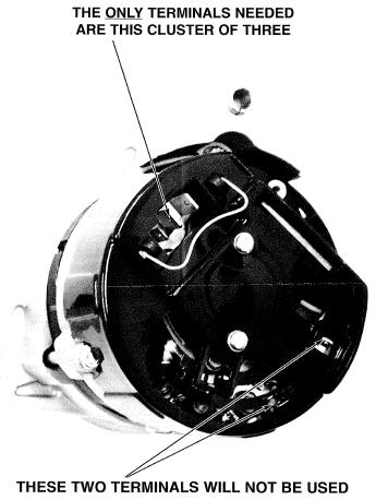
Early internally regulated unit, showing the separate plugs for the + and -, and the IND and B+ terminals. There are two IND spades, although one (nearest the designation) is not as clearly visible as the others. The brown/yellow comes in to one of these from the ignition warning light, then loops back into the harness and out again to the other, possibly to protect the alternator if that plug should become detached from the alternator. There may be a black earth wire on the '-' terminal. The embossing on the rear cover implies it is a common item for 15, 16 and 17ACR units, but 17ACRs on the MGB didn't have this two-plug arrangement. Photo courtesy of Craig Locke:
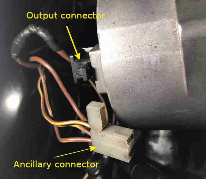
Plugs fitted, there is an 'interlock' between the two so that the ancillary connector cannot be removed or fall out unless the output connector has already been removed, probably to protect the alternator from excess voltage/current. I doubt it prevents the plugs being put back in the wrong order though, and the engine run with only one in: (Martin Ward)
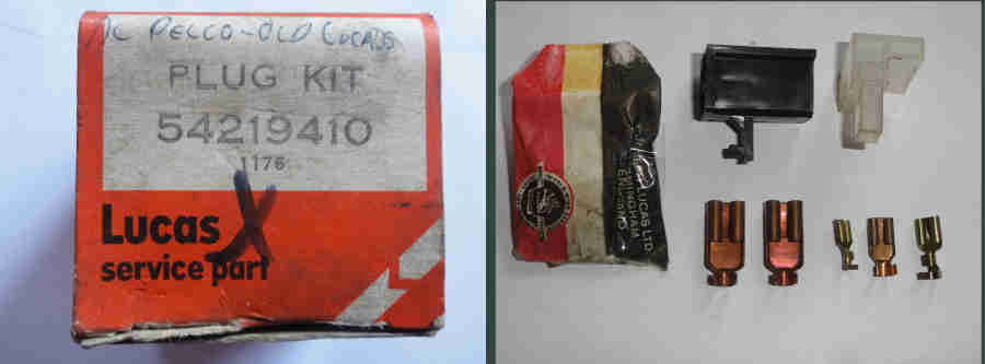
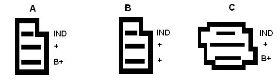
Lucas connector kit 54219410 for the above: (Nigel)
The various connection arrangements used over the years:
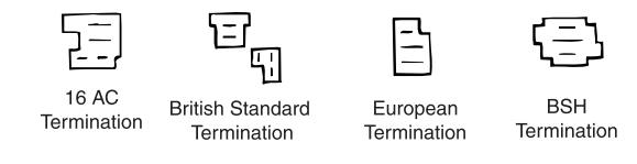
This from Brown and Gammons subdividing the 'European' termination into Type A and Type B:
- Type A (battery sensed) having a rectangular plug with two large and one standard spades, the centre large spade being the output, the other large spade being for battery sensing, and the standard spade for the IND connection.
- Brown and Gammons are showing what they describe as a battery sensing alternator GXE2213 1975-78 but tell me that it has the Type A connector not the Type C/BSH. Not having any in stock they were not able to tell me the output current.
- Type B (machine sensed) being physically the same plug and spade arrangement as for Type A but the two large spades inside the alternator are connected together, hence either (or both for greater current carrying capacity and less volt-drop) can be used for the output. No battery sensing terminal, and again a standard spade for the IND connection.
- Type C is the MGOC 'BSH' termination and is also 'battery-sensing' having a 'square' plug, large output spade and what appears to be a medium battery-sensing spade and a small IND spade. However this differs from the MGOC drawing and Peter Mitchell's plug where the two smaller spades are the same size (confirmed by Nigel Kidd), I suspect the B&G drawing is trying to represent the tapered tip of the battery-sensing spade that is apparent on this diode pack but have labelled them incorrectly! I'm not aware of an alternator available today that is compatible with this harness connector
One thing to be aware of is that some sources show the output terminal as B+. If there is no '+' terminal on your alternator, but there is a 'B+', then it may well be the output. But if you have both + and B+ terminals then work to the principle that + is the output and B+ is the battery sensing terminal. The B+ terminal can safely be connected to the output terminal in the alternator plug if you only have output and indicator wires in your harness.
1972 alt plug in the Euro style, showing a single large brown and the smaller brown/yellow (photo David Bolton):
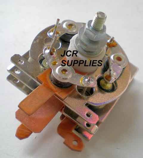
15/16/17ACR machine-sensing diode pack for this style of plug, with two large (9.5mm) output spades connected together:
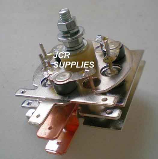
This is a battery-sensing diode pack, but to the later design with two standard-sized spades. The lower one with chamfered corners although they were both the same on original alts, see below. The BSH connector thin brown connects to the chamfered spade (B+), the brown/yellow to the unchamfered standard spade. Note that the central large spade is about double the width of the other spades, which would make it 12.5mm, despite the description stating it is 9.5mm, which is the size of the large spades in the Euro connector. Image from JCR Supplies as being for an 18ACR alternator:
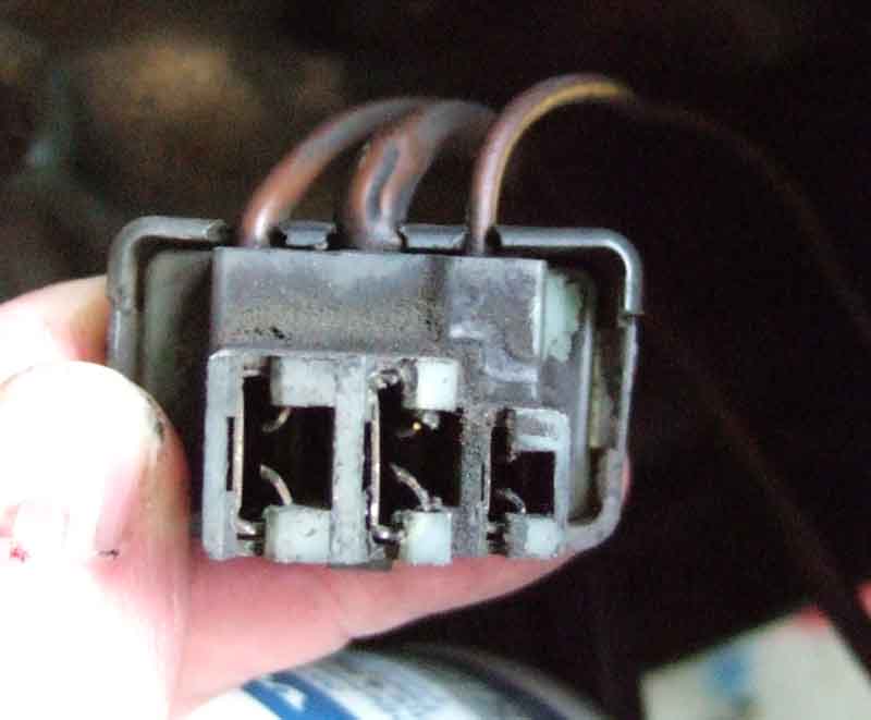
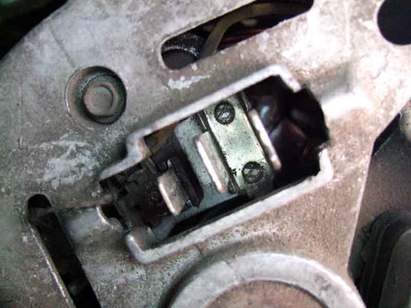
Nigel Kidd's 18ACR from a 1978 showing how the shape of the cut-out in the rear cover prevents the plug being inserted the wrong way round, which would otherwise be possible as the two outer spades are both the same size. This also shows that unlike the JCR diode pack above the two small smaller spades are the same shape:
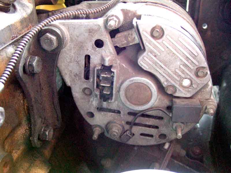
General view:
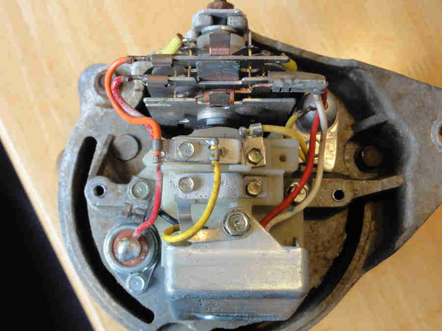
Date code '1878' showing it is an original:
Ditto the 14TR voltage regulator with its 1278 date code:
Peter Mitchell's 78 plug also showing one large and two standard spades as in the 'BSH' connection above:
Bee's alternator showing the two large and one small spade i.e. 'European' of either type A or B. Definitely a replacement unit as the voltage regulator is a 21TR with a 1987 date code. This appears to be an A127 with metal back plate, probably 45 amps. Also available with spade terminals at 55 and 65 amps, and 70 amps with stud output terminal:
Looking straight into the connector, the two large spades do seem to be connected together i.e. a type B:
An A115-45 alternator from a Metro, the two large spades are definitely connected together here:
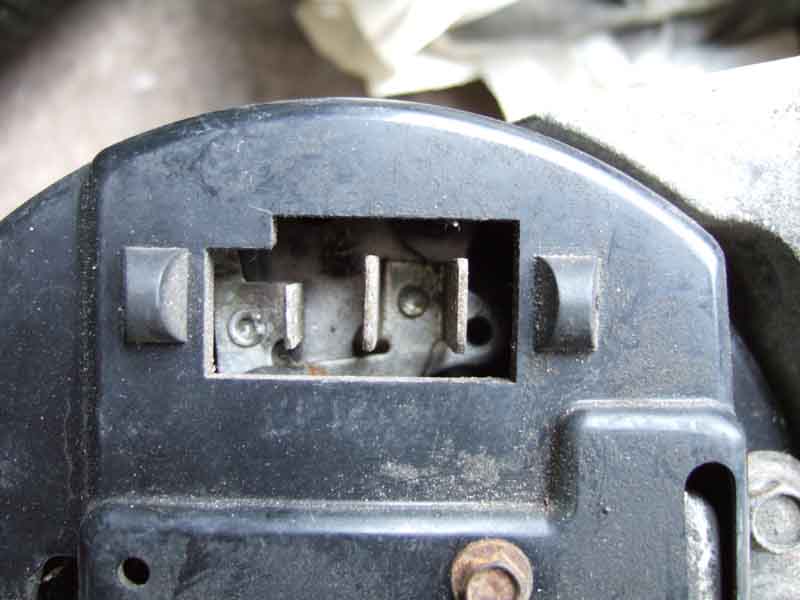
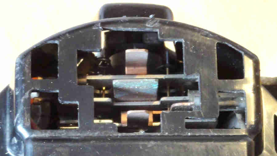
Image from Moss USA showing a 'European' or type B three-pin connector with two large output spades and the smaller Indicator spade, but also two additional spades which aren't used:
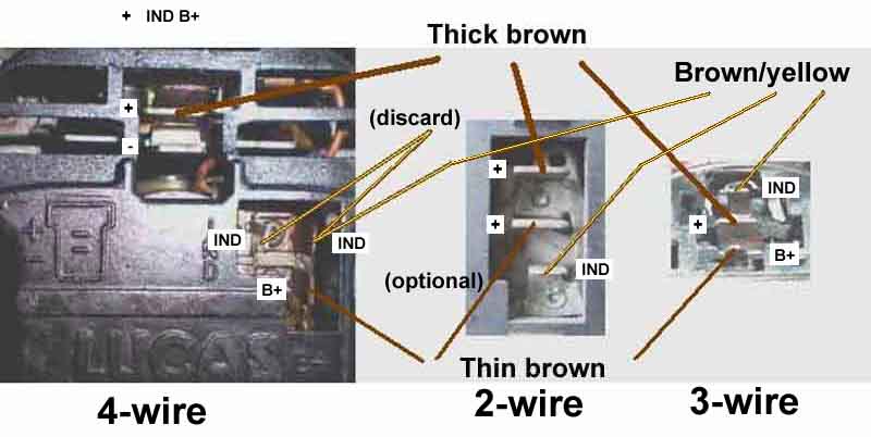
October 2014: Converting between the various connection arrangements. As shown above 4-wire alternators have two large spades in one plug, the '+' terminal is the output, the '-' terminal is an earth terminal (unused). The other plug has three terminals - two IND terminals side by side and the B+ or battery sensing terminal below them. 2-wire alternators have two large spades and one small, both the large spades are connected together and are outputs, the smaller spade is the IND terminal. 3-wire alternators have one large spade and two small, with one small spade having chamfered corners. The large central spade is the output, the plain small spade is the IND terminal, and the chamfered small terminal is the B+ or battery sensing terminal. When converting from the 4-wire discard the loop of brown/yellow that goes between the two IND terminals. When converting to the 2-wire optionally connect the thinner brown to the second output terminal to reduce volt-drop and improve system voltage. When converting to the 3-wire all three wires must be connected as shown:
See also this PDF from Moss Motors on how to convert from the 5-wire 2-plug system to the later 1-plug system.
V8 (1975) AC-Delco alternator, same 3-pin plug, but this time only two wires (normally - the second output wire is my modification giving a boosted voltage supply to the cooling fan relay for improved performance). Two large spades in the alternator both joined together i.e. both output spades plus the smaller Indicator spade: