
Radio interference suppression capacitor
The physical arrangement of the ballast wiring, from a 1980 UK model:
There is a white/light-green tail on the left that goes to the coil positive and the starter solenoid bypass terminal.
On the right there are two tails - one is a white which comes from the ignition switch and the ignition relay operate terminal, the other is a white/brown that goes to the in-line fuse for the tach, indicators, heater fan and heated rear window on GTs.
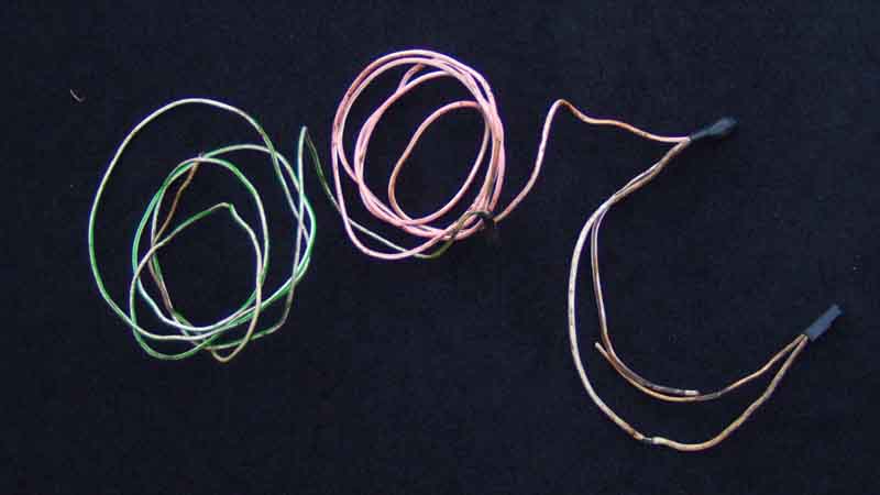
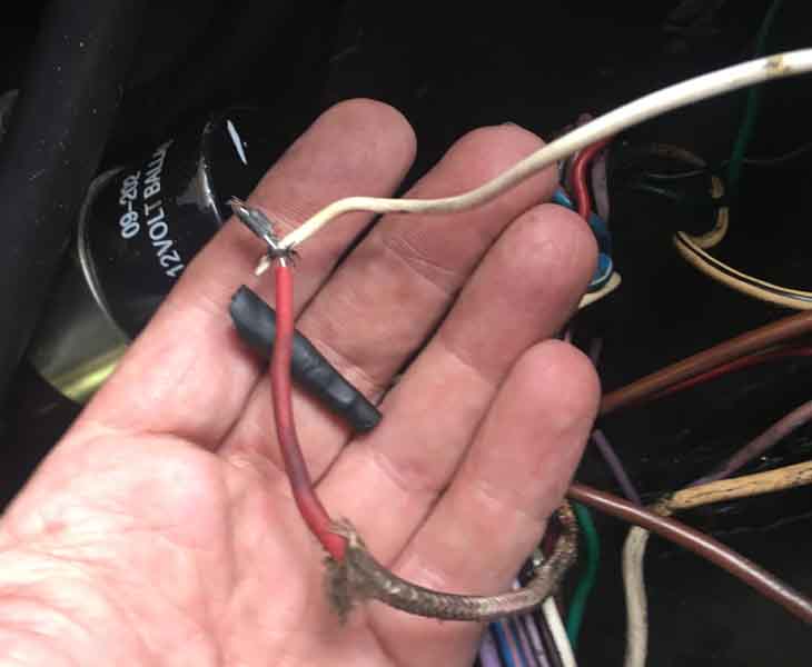
This from a UK 1975 has much thicker resistance wire in its own braided sheath, the crimped (the resistance wire cannot be soldered) connection pictured had parted inside the wrapping which meant the engine would start but cut-out again as soon as the key was released: (Colin Grimsley)
Note the coil is marked '12v ballast' which is how many are marked these days even though it is a 6v coil 'for use on a ballasted system', which is how they should be labelled.
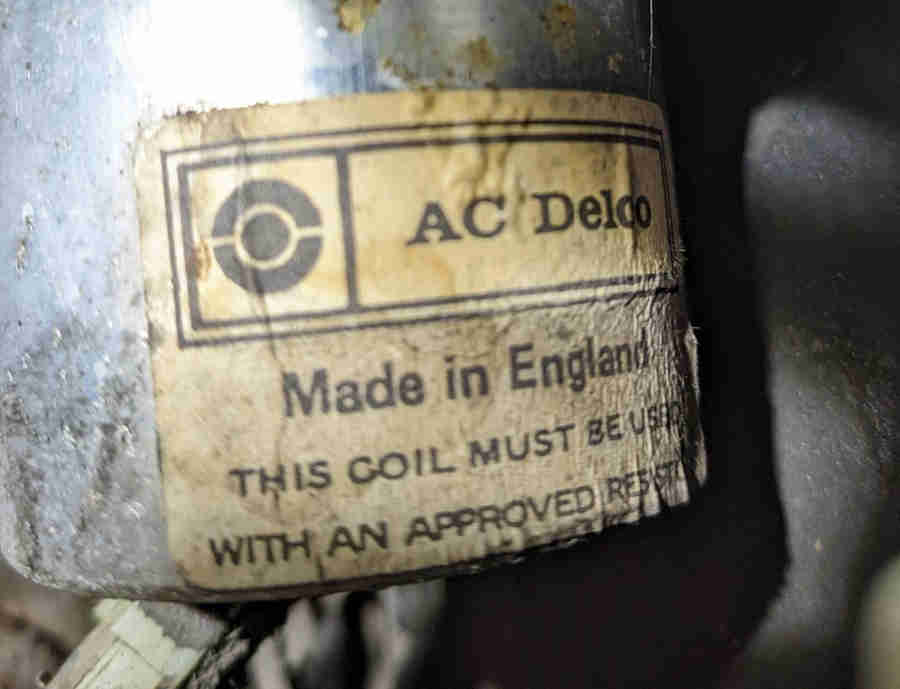
This AC Delco coil has 12v embossed in the can:

But also has a label saying it must be used with an 'approved' resistor:
The second example I have come across, this is from Peter Mitchell's 1978 UK car. The primary measures 2.2 ohms so it isn't a 12v, a 12v sport or a 6v! In this case the requirement for a resistor would be to prevent it overheating, but if it is any more than 0.3 ohms it would be degrading the HT spark energy, and with the factory ballast of 1.6 ohms it would be significantly degraded and may be why Peters car has been running poorly for a while. There is no mention of AC Delco coils being used in Clausager so it must be a replacement and is a good example of why replacement coils must be measured regardless of what the supplier, the packaging or the coil itself says.
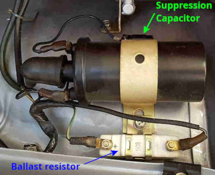
Not used on MGBs from the factory but other marques and models, and some after-market coils for the MGB, may have a discrete ballast resistor mounted near the coil wired between the 12v supply and the coil +ve. This image from The Classic Z-Car Club shows a ballast resistor below the coil and a suppression capacitor above:
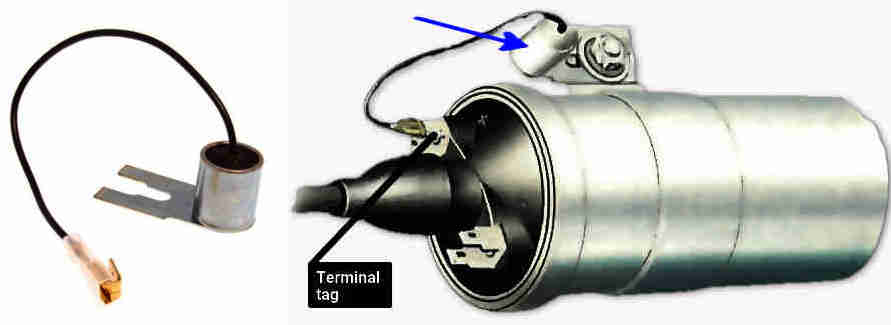
A radio interference suppression capacitor (not a ballast resistor), often found connected to the coil +ve (or SW) with the metal tag under a coil fixing bolt providing the earth connection. Can also be found on the instrument voltage regulator, fuel pump, indicator flasher unit, alternator, electric screen washer pump i.e. anything that can generate electrical noise, may also be rectangular:
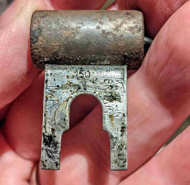 This suppression capacitor is from Peter Mitchell's 1978 MGB and is 1uF at 150v. Typically these days they are described as being around 2.2uF at 100v, the values are not critical:
Note that suppression capacitors are always connected to the coil terminal that carries the 12v supply from the ignition switch or relay regardless of whether they are positive earth cars, positive earth cars converted to negative earth, or originally negative earth cars (Mk2 on) including both CB and RB. The same goes for all other places they are used i.e. always the on 12v supply terminal to the component.