North America 1968 North America 1969-75 North America 1976-on UK 1977-on
North America 1968 A simple circuit where the manual test switch merely tests the bulb and the 12v supply to it:

North America 1969-75 A more comprehensive circuit that tests all the wiring to and from the balance switch and bulb, only the switch itself is untested:

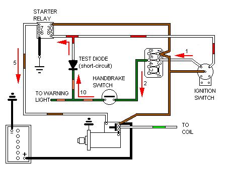
North America 1976-on A completely different approach. No manual test switch, the balance switch now only lights the handbrake warning lamp, and only when the ignition is on. The handbrake switch lights the same lamp, and for some reason the (USA) powers that be decided that the lamp should also be illuminated while cranking, even though the handbrake will almost certainly be on anyway! Not unreasonable for automatics perhaps, when one has used Park rather than the handbrake, but not relevant to MGBs by that time. The wiring to and from the balance switch isn't tested at all, one wonders why they bothered, especially when if the diode fails short-circuit it causes the starter to crank continuously! (In which case drop the handbrake ...):

UK 1977-on According to the schematics all this system does is light the handbrake warning lamp when the handbrake is on or when cranking with it off (even though the handbrake is likely to be on and illuminating it anyway while cranking). No brake imbalance switch is shown, so completely pointless, especially as it has the same problem when the diode fails short-circuit and causes the starter to crank continuously as above. However the lack of brake balance switch seems to be an omission in the schematics as all the cars checked do have the switch and wiring, making it the same as for North America, so the switch has been included here:

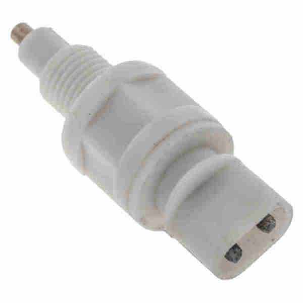
Switch AAU2454 mounted under the master cylinder, but the threaded portion can break leaving the switch dangling: (Graeme Stoten)

AAU2454: (Moss Europe)
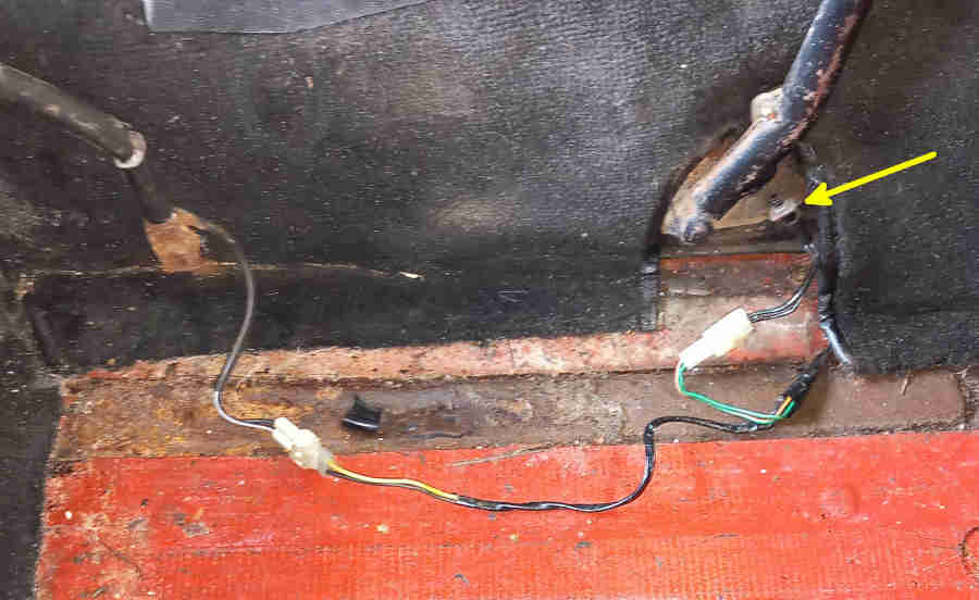
The UK seat-belt and handbrake switch wiring:
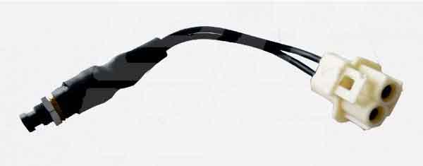
The handbrake switch used is AAU2492: (Brown & Gammons)
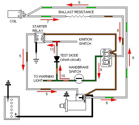
The real problem comes when turning off the ignition - the starter keep cranking! Once the ignition switch has operated the starter relay 12v is sent to the solenoid (5). With this operated 12v is sent on the white/green circuit to the coil +ve (6), and backwards through the ballast resistor to the fusebox (7, 8), even though the ignition switch is off by this time. 12v on the white/brown at the fusebox passes through the fuse onto the green circuit to the handbrake switch (9), which is normally closed when cranking i.e. handbrake pulled up, and on the green/orange to the diode (10). With the diode short-circuit 12v flows backwards through it onto the white/red and thence to the starter relay (11), which keeps it operated and keeps the starter cranking. Hence dropping the handbrake is the only way of stopping it cranking short of pulling the wires off the starter relay or disconnecting the battery:
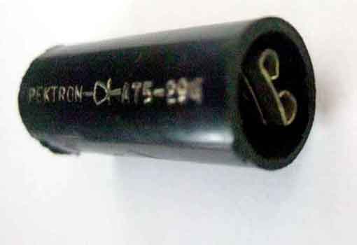
Warning light test diode showing the male connector for the white/red wire ...
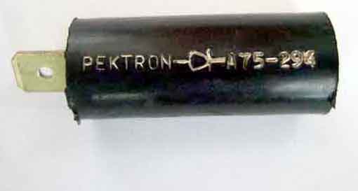
... and the recessed female connector for the green/orange wires: