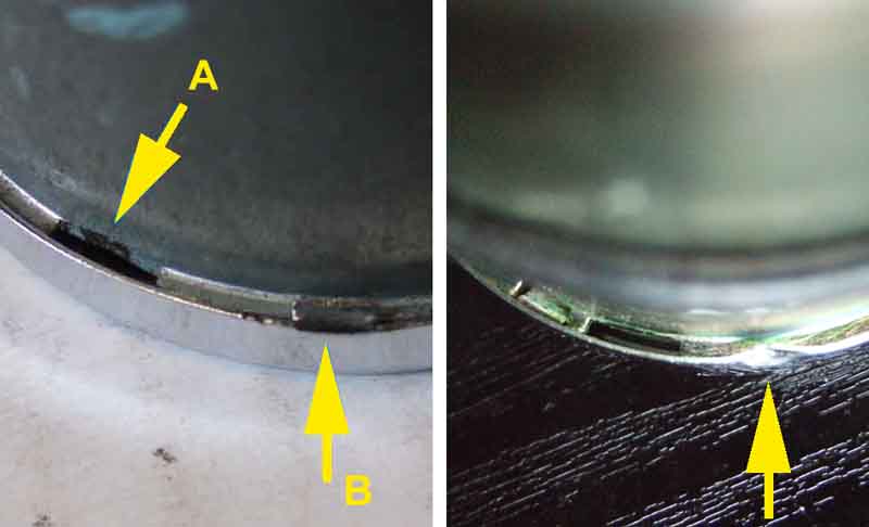
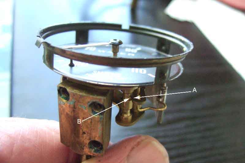
Removing the bezel and glass - there should be three cut-outs in a flange on the case (A), and either a folded-over tab or just crimp (B) to lock behind the flange. The bezel needs to be twisted round until the tabs or crimps line up with cut-outs:
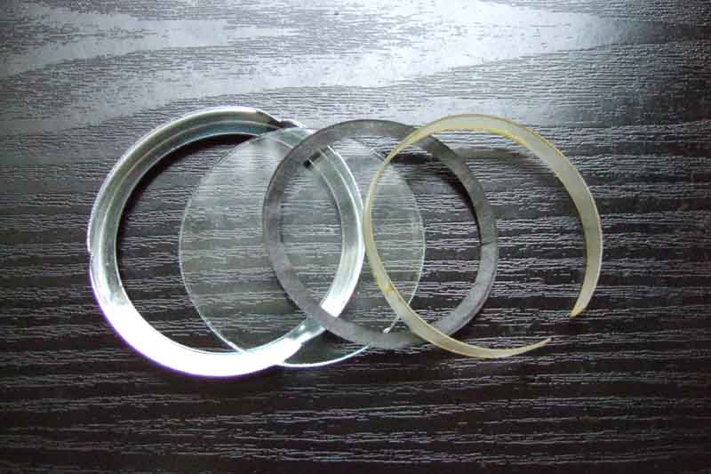
Under the bezel there is the glass, under the glass there is a gasket, and under the gasket is a cylindrical translucent strip to diffuse the light from the internal bulb onto the dial and pointers. This gasket is flat fibre but sometimes they are rubber which can glue things together, in which case the bezel may have to be levered a bit until it comes free:
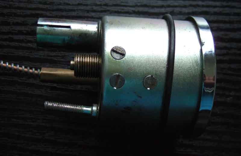
Three screws on the outside of the case secure each of the mechanisms (three more on the other side of the dual gauge). The rubber O-ring on the outside of the case (probably originally square-section, this on a (failed!) replacement gauge is round) to buffer the instrument against the dash panel:
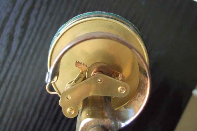
The edge of the dial has a tab that locates into a smaller cut-out in the case flange:

The innards of the dual gauge - two completely separate mechanisms:
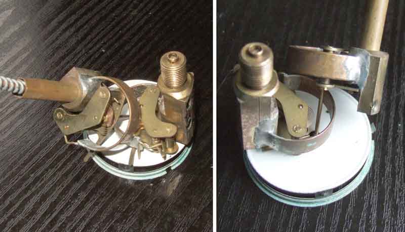
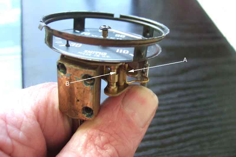
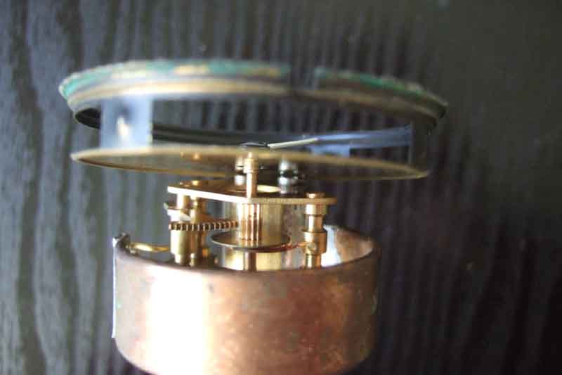
General views of a single gauge, exactly the same principle but larger components for clarity:
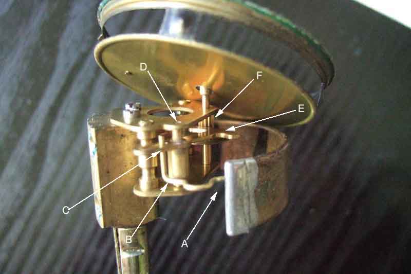
The free end of the tube A pulls on the link B which moves the short end of the lever C on it's pivot D. The long end of the lever E rotates the spindle F using a rack and pinion arrangement and hence the pointer.
At rest the short end of the lever A is on its stop B
At maximum movement of the pointer the short end of the lever A has only moved about 1/8" from its stop B