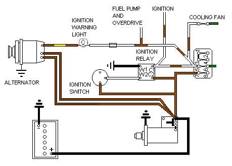
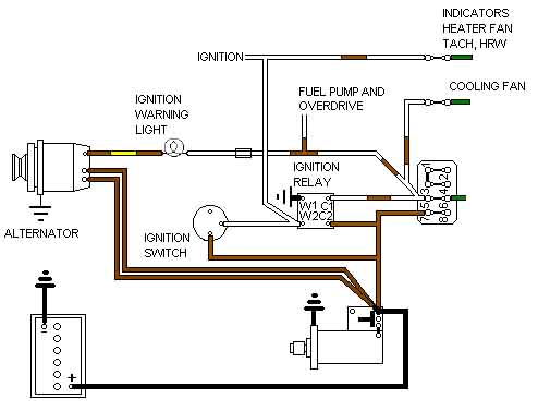
Alternator with internal regulator (16/17/18ACR)
UK with Ignition Relay - 1977 (1978 on)

Note 1: All ignition-powered circuits are fed off the ignition relay. The Ignition unfused, the cooling fan comes off its own in-line fuse and separate green circuit, the remainder of the fused ignition circuits being fed off the fusebox green circuit, i.e. two separately fused green circuits.
Note 2: There are two browns from the alternator to the solenoid, some schematics showing them as two thick output wires i.e. using a '' alternator, and some showing one of them being standard gauge i.e. using a '' alternator.
Note 3: Some schematics show three browns up from the solenoid to the cars electrics - one to the fusebox and ignition relay, one to the lighting switch and ignition switch, and the third to the starter relay and hazard flasher fuse.
UK with Ignition Relay - 1978 on

Note 1: The Ignition is now fed directly off the ignition switch, and the white for that becomes a white/brown where it is extended to the inline fuse and green circuit for the Indicators, Heater Fan, Tach and HRW i.e. also off the ignition switch. The Cooling Fan remains on the relay via it's own in-line fuse and green circuit, and the rest of the fused ignition circuits remain on the relay and fusebox green circuit. There are now three separately fused green circuits.
Note 2: There are two browns from the alternator to the solenoid, some schematics showing them as two thick output wires i.e. using a '' alternator, and some showing one of them being standard gauge i.e. using a '' alternator. John Wallace's 78 has one thick and one thin using the BCH battery sensing connector.
Note 3: Some schematics show three browns up from the solenoid to the cars electrics - one to the fusebox and ignition relay, one to the lighting switch and ignition switch, and the third to the starter relay and hazard flasher fuse.
