Cables
Dash control
HS components
HS set-up
HIF set-up
V8 set-up
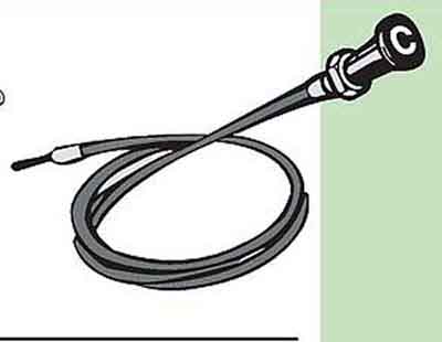
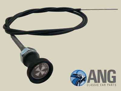
4-cylinder: BHH526 (North America, Sweden and Germany) with BHH653 (UK) similar. However most suppliers show BHH653 as the hard 'shutter' type below as the 'C' knobs are probably NLA:
BHH653 with the short inner for HS carbs:
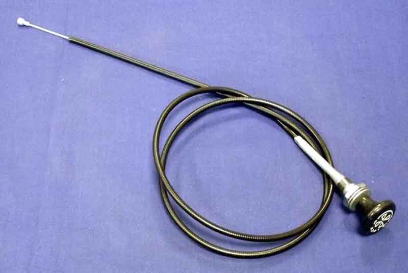
BHH651 for HIF carbs on CB cars with the longer inner:
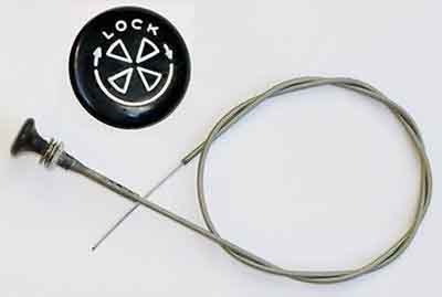
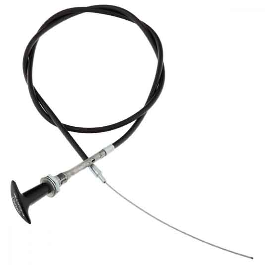
BHH650 from 258001 to 360300 for North America, and from 360300 on for elsewhere (Parts Catalogue). Shown by most suppliers as either the soft or the hard round knob, although a few show the T-bar which would be correct according to Clausager:
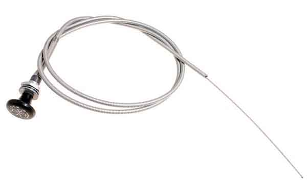
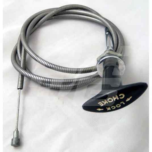
BHH2064 with T-handle and long inner for HIFs, shown by most suppliers, although giving very different years of use: Moss Europe
V8: Current-stock BHH1121 from most of the usual suspects - nipple on the end of the inner but a round knob instead of the T-handle. Also no ferrule on the end of the plastic-covered outer: Motaclan/Leacy
Subsequently (September 2019) spotted this shown as in stock from Brown & Gammons. Wound steel outer, different to mine:
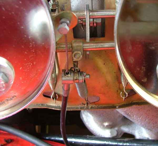
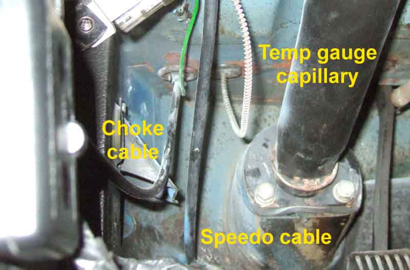
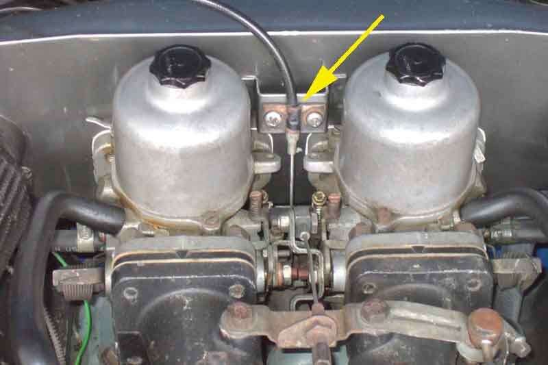
CB choke cable routing for HS carbs and early HIF - via the tab that would be used for the brake pedal return spring on LHD cars. Takes it across a bit more than it needs to, but the cable is plenty long enough to reach up to the carbs, and it stops it rattling against the bulkhead or hanging down:
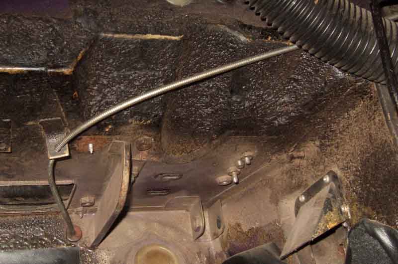
This allows it to rise up to the carbs:
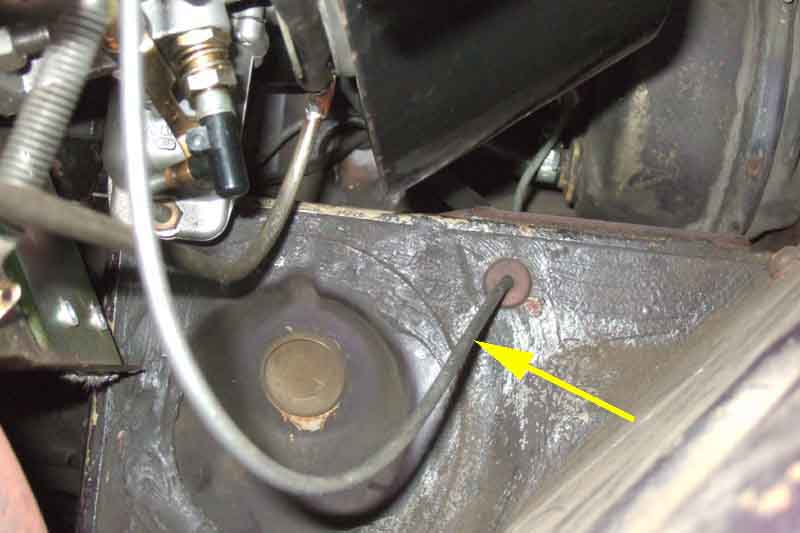
Later top-down HIFs have the cable coming through on the same side but higher up, through a hole under the bonnet hinge: (Clausager)
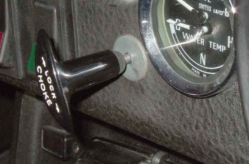
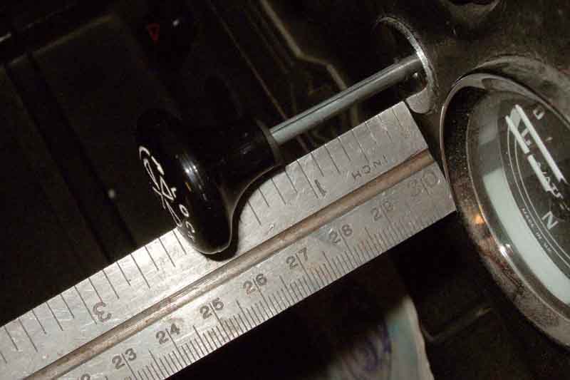
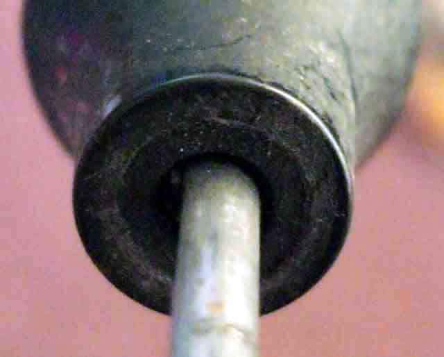
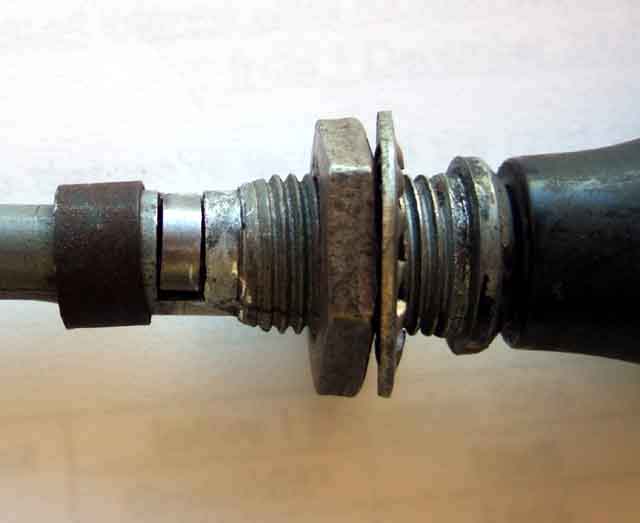
Choke knob fully out - an indication of typical cable adjustment:
Showing how the shape of the shaft and the shape of the hole allow for about 45 degrees of rotary movement of the knob. Shown in the unlocked position ...
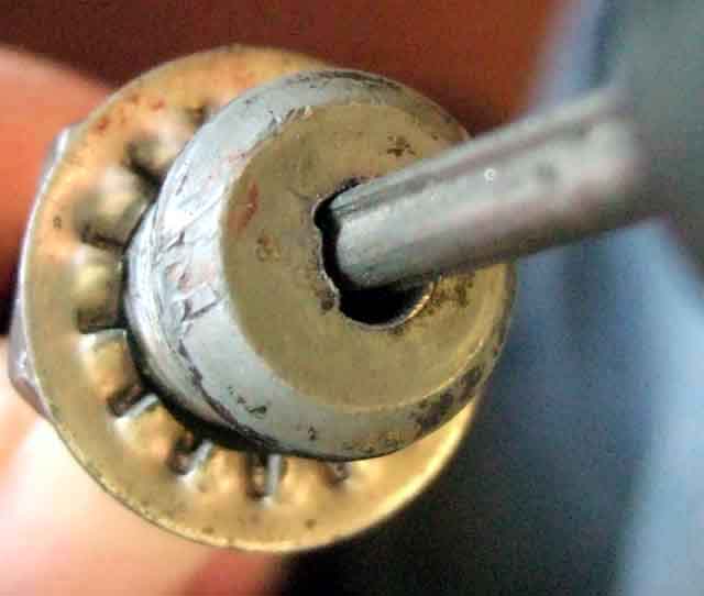
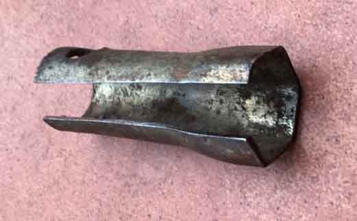
The control shaft is a bit like a 'cam', this shows the 'heel' or low radius side ...
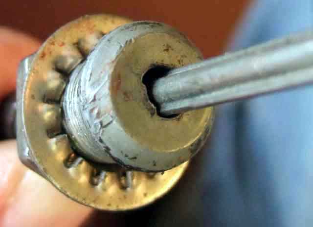
... and the 'lobe' or high radius side:
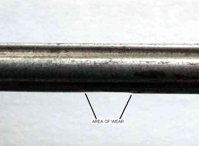
Showing the wear as a polished area on the leading edge of the cam 'lobe' ...
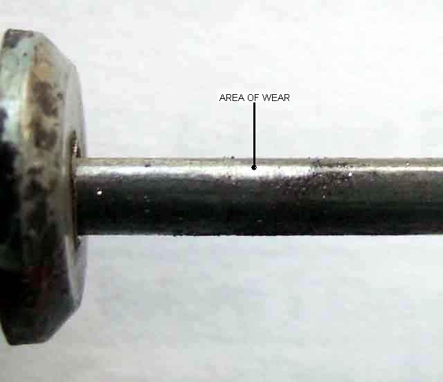
... and how the leading edge of the cam 'lobe' has been worn down. In this case the vast majority of the wear has taken place over a relatively short distance, from about 1/4" out (fast idle) to about 1/2 pulled. This cable is off the roadster, and almost all the choke use occurs in that range - pulled fully and held while cranking, immediately reduced to half-way and locked as soon as it fires, then gradually reduced to about 1/4 pulled as it warms up (while driving) unlocking and locking each time:
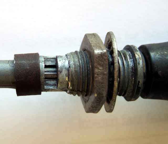
The spring for the locking mechanism, partially removed, showing the rib in the casting that locates in the slot in the spring. Note also the flat in the threaded portion that locates the cable outer in the correct position in the dash:
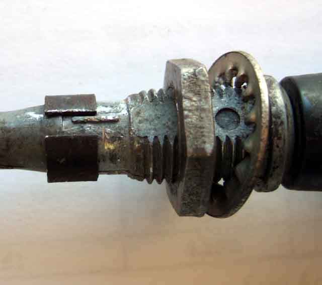
The locking 'wedge' revealed by the spring in-situ:
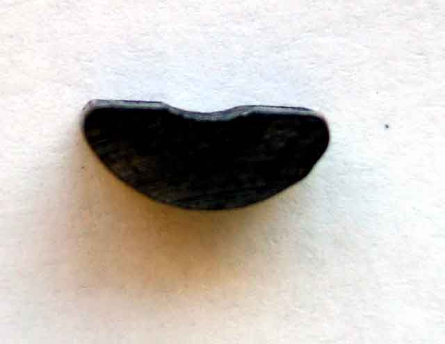
The locking 'wedge' removed revealing the leading edge of the 'lobe' of the shaft:
Probable wear in the flat face of the 'wedge', which is shaped like a Woodruff key. This wear, in conjunction with the wear on the leading edge of the 'lobe' on the shaft, is what causes low spring pressure on the shaft hence failure to lock. Whilst turning the wedge round may aid locking as it will be working on a different face, it probably won't last long. And whilst it may be possible to build-up the top face and bring it back to level (if that face were flat originally) doing a similar job on the shaft is a different proposition. While you are partially withdrawing the cable at the very least to do this, you might as well replace it altogether and just do the job once and for all (or the next 30 years at least):
A tool to aid removal of the choke cable from the dash - a box-spanner with a slot cut lengthways. In this case an old plug-spanner, which will have holes for a tommy-bar, which will give you more force - given enough space at the back: (Martin Roberts)
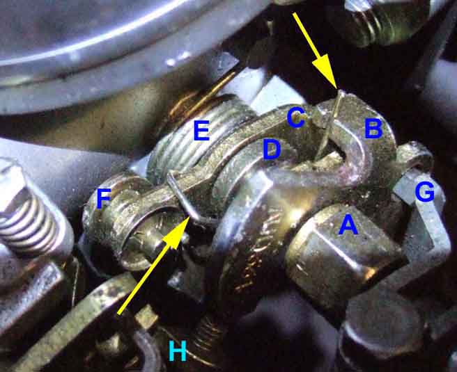
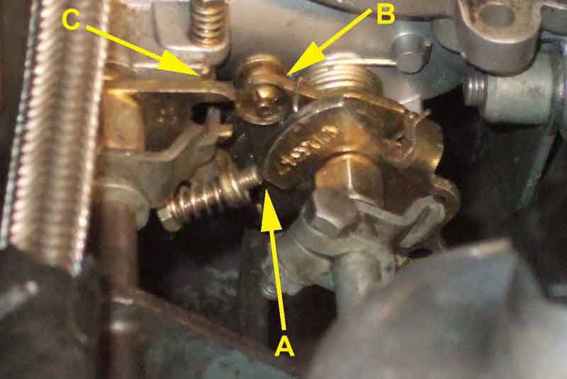
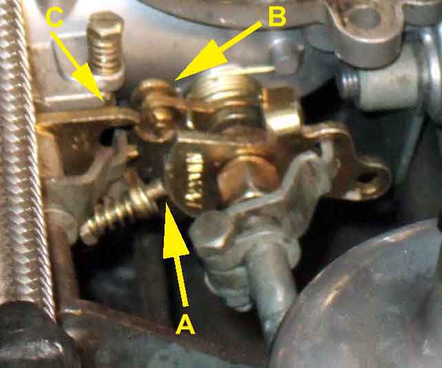
It's all a bit complicated with interconnecting shaft clamp (G), fast-idle cam (B), fast-idle screw (H) and return spring (ends arrowed), choke cam (C), jet operating lever (F) and return spring (E), pivot tube (not shown) and spacer (D), special bolt (A) and spring washer (not shown).
As the choke control is pulled clamp G rotates fast-idle cam B which opens the throttle butterfly via fast-idle screw H. Initially choke cam C doesn't move, but when the fast-idle cam has moved so far a tab catches up with the choke cam and starts rotating it, pushing jet operating lever F down. Special bolt A clamps up the spring washer and pivot tube to the carb body and is the socket for the interconnecting shaft, the two cams, spacer and return springs rotate on the pivot tube:
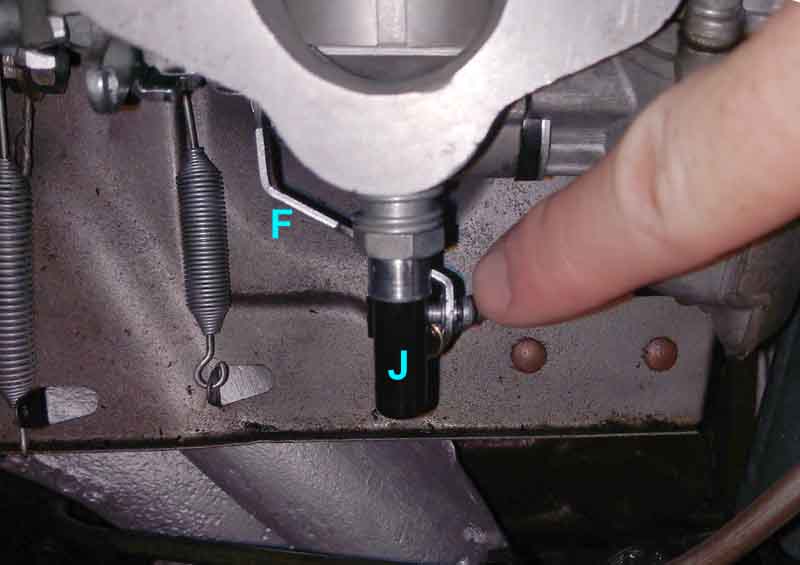
Jet operating lever (F) pushes jet (J) down to enrich the mixture. It seems odd that the lever crosses over behind the jet and over the jet tube to the float chamber, but that's how it is: (Bill Etter)
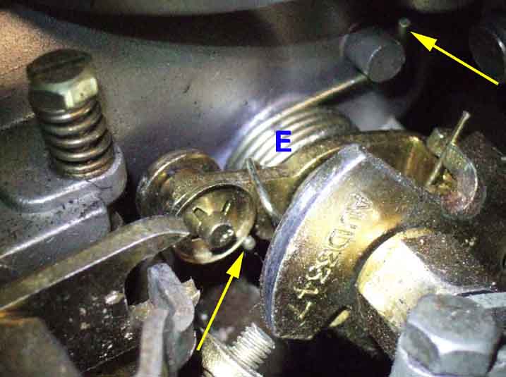
As the choke control is pushed home choke cam return spring E returns the choke cam, pulling the jet operating lever up and the jet with it reducing the enrichment. At this stage the fast-idle cam is returning with the choke cam, reducing the amount of fast-idle as well as the amount of enrichment. When the jet is fully up the choke cam stops moving, but the fast-idle spring continues to return the fast-idle cam, reducing fast-idle to zero. The ends of the choke cam return spring (E) arrowed:
If the jet is sticking down then remove the screw connect the jet operating lever to the bottom of the jet. If this allows both the jet to slide in the bearing easily, and the choke cam operates and releases easily, then look very closely at how the lever interfaces with the jet. The two faces should lie flat against each other, the two holes be in line, and more importantly the lever should not have to be pushed up to the jet to touch it, only to spring away again when released. Of course if, with the screw between the two removed, one part is obviously binding and the other free, you know where to look next. If it's the choke cam then you need to look at the two cams pivoting on the pivot tube.
... and specifically of the cable: (Photo John Bilham)
Choke knob fully in - cable lever angled downwards about 30 degrees. Adjust the position of the inner in the clamp screw so that with the control pulled about 1/2" the jets are just about to start moving down and commencing enrichment. Adjust the fast-idle screws at this point to get about 1000rpm and a balanced air-flow with a warm engine:
Choke knob fully out - cable lever angled upwards a similar amount. This is approximate but if the angle is too low when fully in it makes it stiff to pull, and if too high when pulled you may not get full movement of the spindle and cams, The choke lever is clamped onto the interconnecting shaft so the position of this can be adjusted to get the correct range of cam movement with the correct range of lever movement, and to get the cable outer under the trunnion for a 'straight pull':
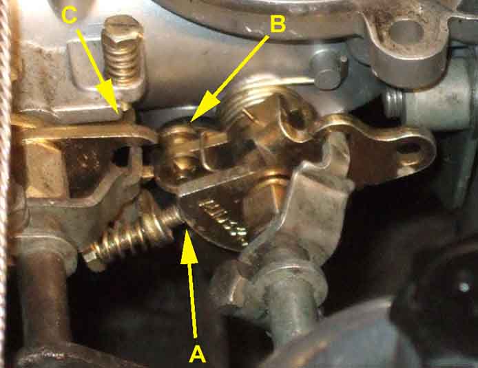
Choke knob fully in - small clearance between fast idle screw and cam, and right at one end of the cam (A): Jet lever fully raised (B): Throttle butterflies on idle screws (C):
Fast idle - fast-idle screw part-way round the cam (A) and slightly opening the butterflies (C). Jet lever still fully raised (B):
Full choke - fast-idle cam rotated nearly all the way (A): Throttle butterflies opened further (C): Jet lever fully down (B):
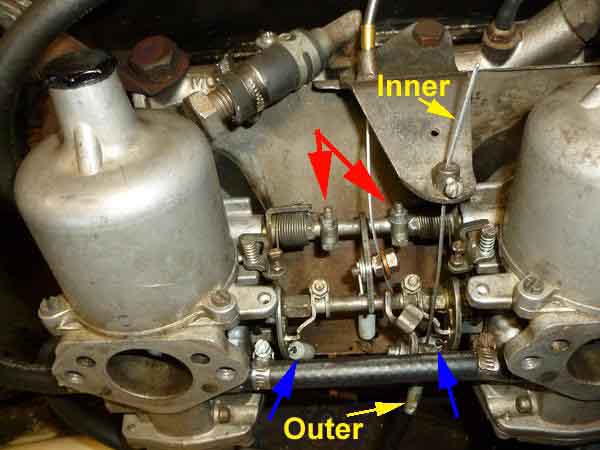
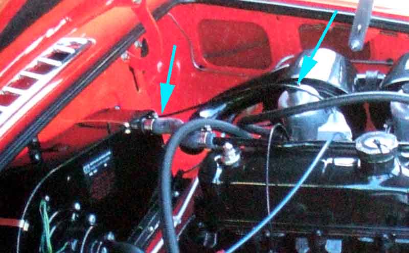
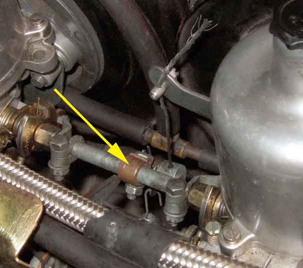
RBs used a 'top down' as here, but at the carb the the situation is the same for both. With the choke control fully released the choke lever 'A' should be angled downwards as here. Just over half-pulled it should make an angle of about 90 degrees to the cable, so that when fully up it has fully rotated the choke cams. If it is higher than you may not be able to get full enrichment and fast-idle, if it is pointing too far down with the control fully home it can be stiff to start moving. The choke lever is welded to the interconnecting shaft so to get the correct angles of the lever at zero and full choke the position of both choke clamps with the fingers that engage with the cams (D) on the interconnecting shaft have to be adjusted. 'B' is the 'fast-idle' marker and when it is directly under the fast-idle screw 'C' enrichment is just about to start, this is where the fast-idle speed is set with the engine warm. Note which cam hole the clamp finger 'D' is positioned i.e. the small one not the large one:

To position the choke cable correctly pull the cabin control out by about 1/2" i.e. for fast-idle only. Then with the clamp screw on the inner slackened:
- Bottom-up cable - pull the inner through the clamp screw to lift the lever
- Top-down cable - pull the inner down while sliding the trunnion and lever up
The outer is clamped to a bracket on the air-box and this is the only adjustment:
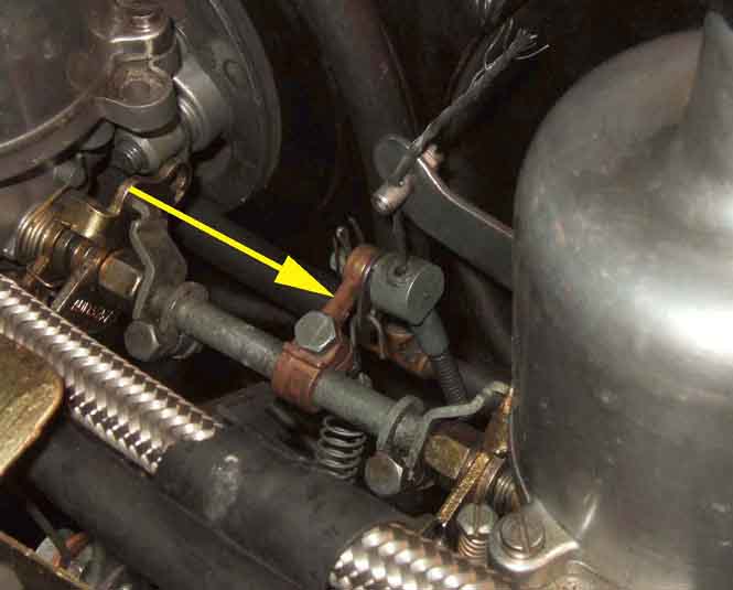
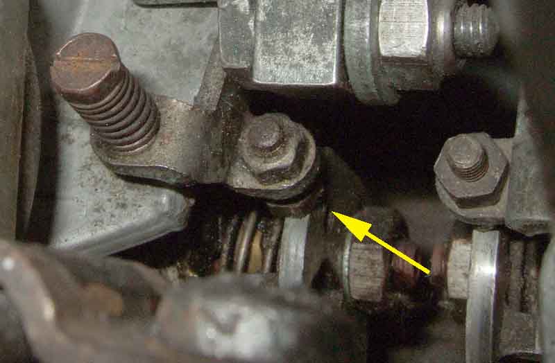
The inner ends in a nipple that slots into a trunnion (arrowed) which engages with both choke cams, With the nipple in the trunnion the outer is pulled through the clamp to set the adjustment. Do this with the dash controlled pulled about 1/4" i.e. to the fast-idle position, then position the outer in the clamp to turn the choke cam and put its reference mark under the fast idle screw. Ordinarily I'd do this with the control pulled about 1/2" but with this cable that would mean the clamp would be on the plastic part of the outer instead of the metal ferrule at the end, and could slip like the plastic-covered heater cables:
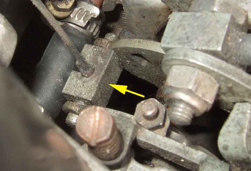
Choke fully released. The cam is just clear of the fast-idle screw, the enrichment start point is when the engraved line above the small hole in the cam is under the fast-idle screw:
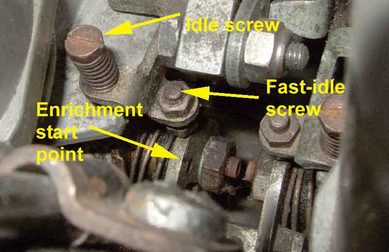
Choke pulled for fast-idle only, enrichment point under the fast-idle screw. These are a pain as there is a lock-nut on top which has to be slackened and tightened, and it is the hex underneath that has to be turned to make the adjustment. The book says at the enrichment start point to adjust the screws for about 1000rpm with balanced air-flow when warm. But Vee needs almost full choke for a few seconds at a cold start, and only gradually eased back from there, which causes the engine to race from too much fast-idle, so I have the screws backed off more than that:
Choke valve assembly: (John Maguire)
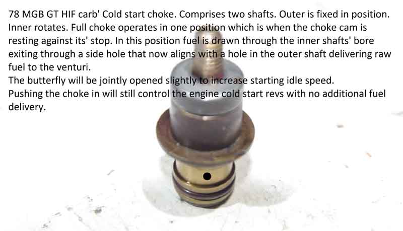
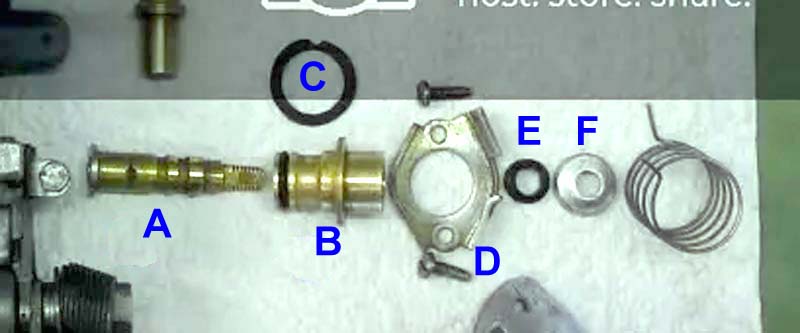
The 'exploded' valve - 'A' the rotating part - do not fit O-rings into either of the grooves in this; 'B' the fixed body, with an O-ring at its inner end; 'C' the 'cold start' seal between the valve body and the carb body; 'D' the clamp plate and screws that hold the valve in the carb body; 'E' the external seal on the rotating spindle; 'F' the dust cover over the external seal. The valve body and the cold start seal both have notches, and must be orientated to fit round the upper clamp plate screw. The clamp plate is fitted with the flanges facing outwards, and with the larger flange towards the carb manifold flange;
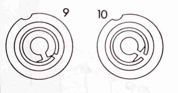
HIF valve from Haynes showing the notch in the valve body in the upper position. '9' shows the valve just about to start enrichment when the engraved line on the enrichment cam will be under the fast-idle screw, '10' shows maximum enrichment.