1968 to 74 North American unboosted dual master 37H2780, two outputs to a separate manifold unit that contains the pressure failure switch:
Internals from Haynes:
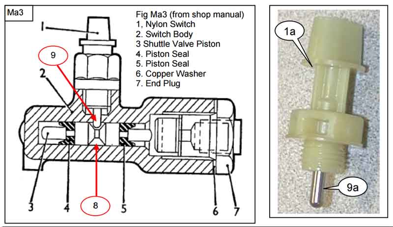
The remote pressure failure switch assembly 13H5905: (Somerford Mini)

Internals from Moss Motors:
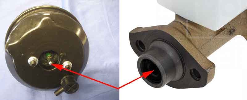
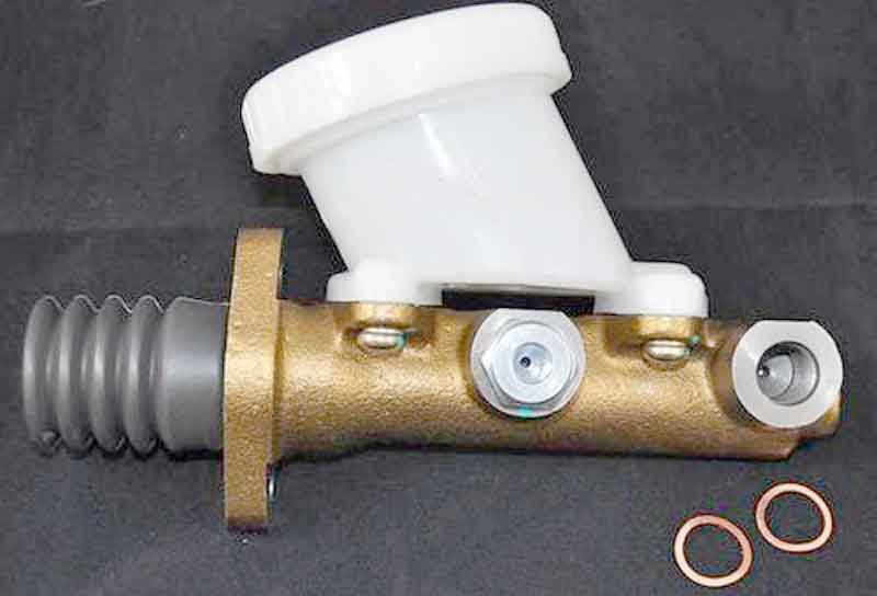
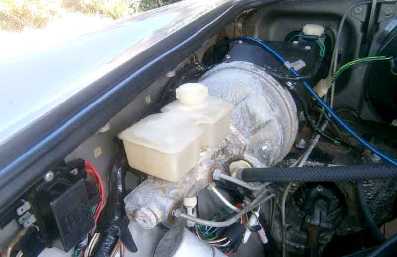
1974-on North America and 1977-on RHD dual brake master with integral servo:
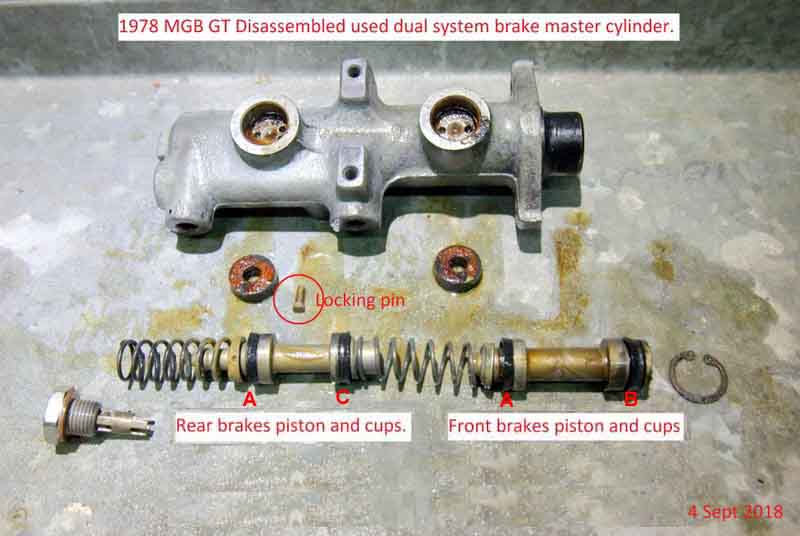
Next three images from John Maguire in Australia:

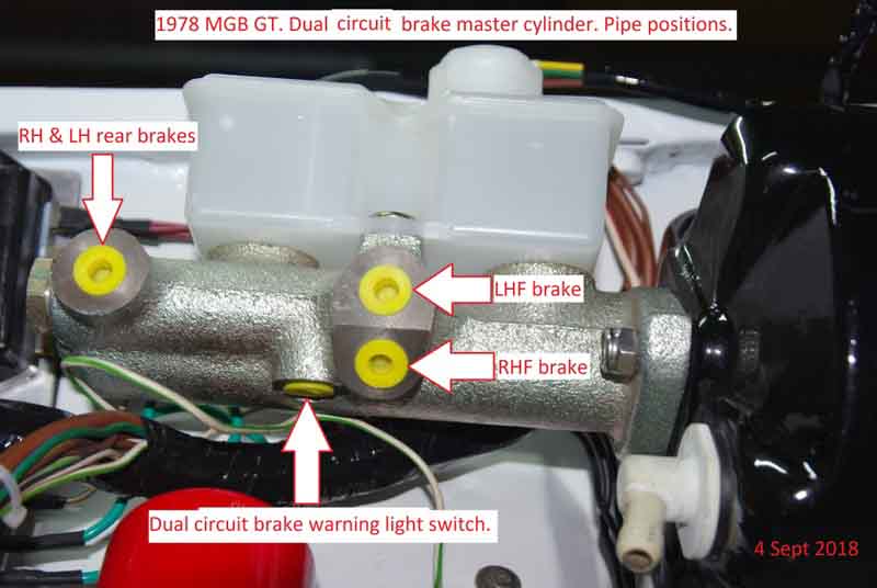
It's important to note that the hydraulic ports have a metric thread whereas the balance switch port, and the rest of the unions in the brake system are Imperial, as described by John Twist in his excellent rebuild video). There can be two sizes of O-ring for the shuttle valve and two types of seal for the reservoir mounting, not all rebuild kits contain all parts.
Care is needed with the switch (AAU2454). It's only plastic and screwed into a casting it can seize, snapping off if too much force is used as here: (anon)

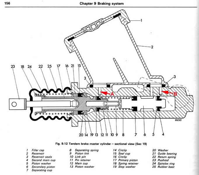
Drawing from Haynes. Note the reservoir on the MGB can be rectangular or wedge-shaped. In the images above John has removed the plug and spacer for the differential switch unit from the master but not the differential unit (shuttle) itself. The two O-rings 17 are probably what fails and causes fluid to leak from the switch. The BL Parts Catalogue shows repair kit 18G9081 which only came up with a couple of sources in the US (which didn't look like they had these O-rings) and an Amazon page (unavailable). According to John Twist in the above video there can be two sizes of O-ring for the shuttle valve and two types of seal for the reservoir mounting, and not all rebuild kits contain all parts. But the Amazon page listed several equivalent part numbers and Googling those one took me to Brown & Gammons GRK1004. This has several more components than the US sites including some small O-rings which hopefully will be for the shuttle, and also contains the outer seal, washer and housing that John Twist says is not included:

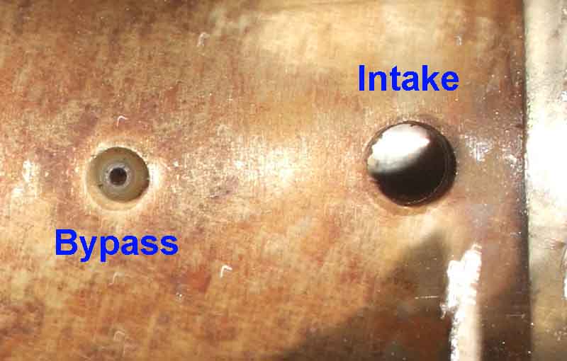
Although Haynes shows different arrangements for the front and rear passages from the reservoir to the main casting John Maguire just shows two identical seals and that all John Birbeck found. John B had fitted a new master cylinder but couldn't get any fluid to flow from the reservoir to the front brakes. There is a passage from the shuttle valve to the front ports, but not down from the reservoir! John M shows two small holes in the casting under the reservoir which are probably the inlet and bypass ports for in front of and behind the pressure seal, perhaps the inlet in John Bs is blocked. In the single circuit master this is a very small passage, which looks like it has been drilled then a bead with a tiny hole pressed in closing most of it off:
From 'How stuff works' but I believe the drawing to be incorrect, the passages from the reservoir to the right-hand cylinder are different to those on the left:
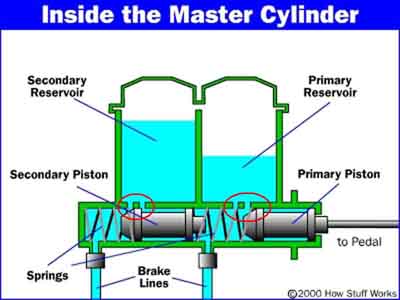
I.e. the inlet or equalisation port should be connected to the space between the two seals on the primary piston, just as it is on the secondary. The locking pin is also omitted above, this is necessary to position the secondary piston in exactly the right place between the two ports with the pedal released. Also it seems logical that the secondary spring should either be stronger or compressed more than the primary spring with the pedal released, to be certain that the primary spring isn't pushing the secondary piston forwards off the locking pin:

Servo:
The push-rod from the servo acts directly on the master cylinder piston: