Flasher Units
Where are they? Indicators/Turn signal types Hazard flasher types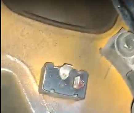
On a 73 RHD roadster:
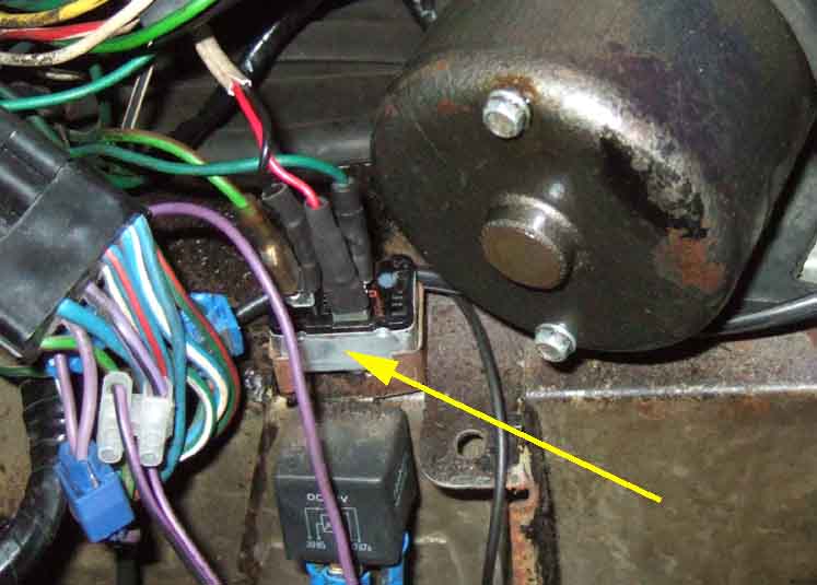
On a 75 factory V8:
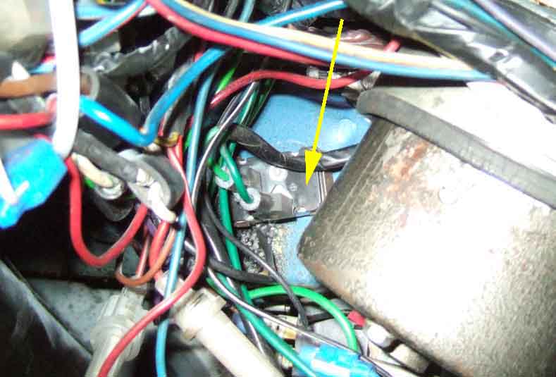
So all in about the same place - to the left of the wiper motor.
Originally the hazard flasher and fuse were behind the centre console with the flasher unit clipped to the right-hand upright beneath the radio:
Later on (probably 77-on) the fuse moved to a more logical position by the fusebox, and the flasher unit was positioned by the indicator flasher: (Nigel)
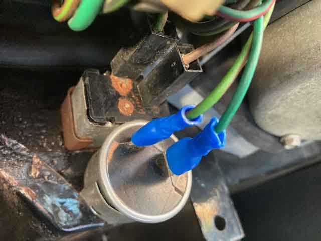
Note one would expect the indicator flasher to be the rectangular unit and the hazard flasher the larger round unit, in which case the wiring shown here would be cross-connected. The indicator flasher should have green and light-green/brown wires, and the hazard flasher brown and light-green/brown wires. However the two light-green/brown wires are not the same circuit and must be paired correctly, normally each pair is a wrapped tail coming out of the main harness so easy to identify. Nevertheless in this case both flasher units work as they should i.e. the indicator lights come on immediately the column stalk is operated, and all four lights flash at the correct rate when the hazard switch is operated.
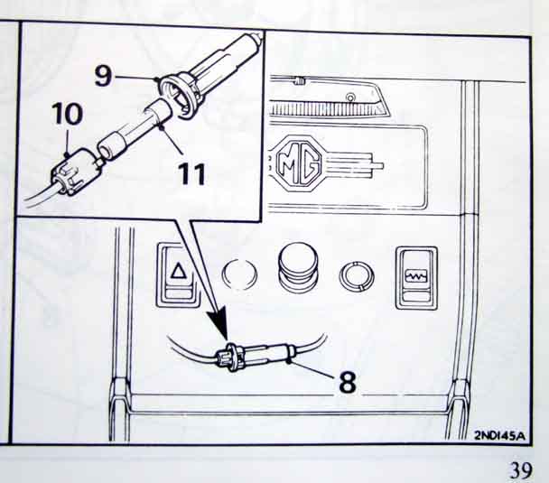
 Early 3-pin FL5 flasher unit. Note that there are at least two versions of the 3-pin type. The third spade is used to light the dash tell-tale(s) in both cases, but it differs according to whether you have the twin tell-tales as on MGBs, or a single tell-tale as on some Triumphs. With the MGB version the 3rd spade is outputting 12v when the flashers are switched off, and so needs the indicator switch with additional contacts to light the appropriate side, and only when the switch is operated. On this version the tell-tale flashes in anti-phase to the corners of the car. On Triumphs with the single tell-tale the 3rd spade is only powered when the flasher unit has clicked to light the corners of the car. With an MGB unit on a Triumph, the tell-tale is glowing all the time when the indicator switch is off. AFAIK the Triumph type will work OK on an MGB, but flashing in-phase instead of anti-phase:
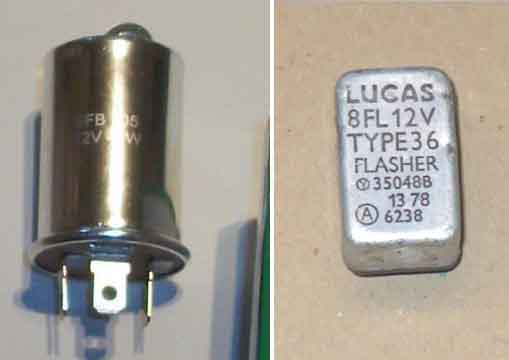
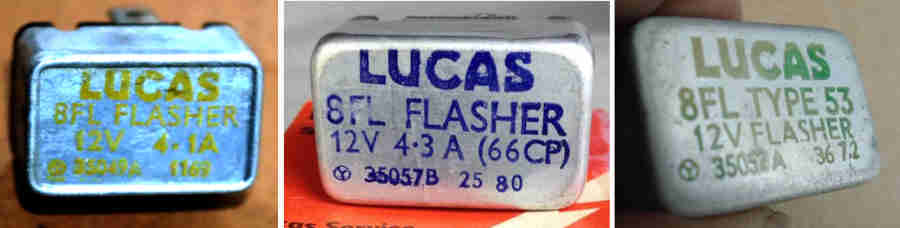
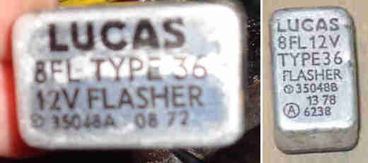 Original FL8 Type 36 35048 for the Mk2 MGB - two types, suffix letter A and B indicates minor variations not affecting operation.
Three other types of FL8 - 41 (4.1A), 43 (4.3A) and 51 each with a different part number all of which need more bulbs i.e. a 5W side repeater to work correctly and will flasher slowly on the MGB:
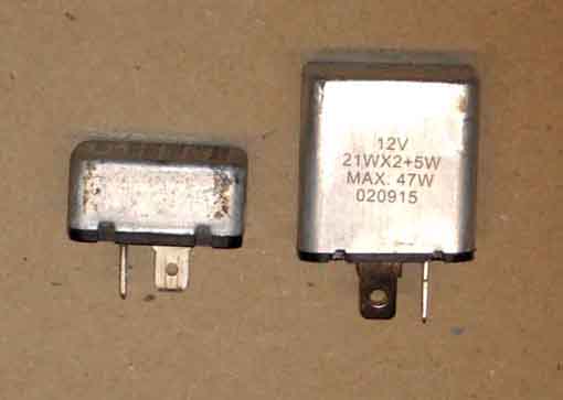
Generic no-name 2-pin from the MGOC (right) seem to be twice the height as the original 8FL, but still fit the spring clip. As indicated these are designed for two 21w watt bulbs plus a 5W wing repeater i.e. they are indicator flasher units and not hazard flasher units. This one from the MGOC in May 2016 is definitely quieter than the original, but more importantly even though it ticks with the engine stopped which the old unit didn't, however because of the additional 5W side repeater it is noticeably slower on the MGB with the engine running than the old unit at 64 flashers per minute instead of 80 flashes per minute, barely above the MOT minimum of 60 flashes per minute. A second one from the same source was even slower at 56 fpm and so not even legal:
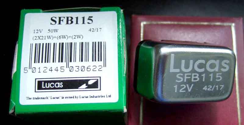
Present-stock SFB115 from Lucas turns out to have hazard flasher internals even though the packaging shows they are for indicators! Three tried of different batch numbers and all the same. The first indication (ho ho) of this error is that when first turning on the indicators nothing happens ... for a second or so which is what hazard flashers do instead of all the bulbs lighting immediately and then after a short pause start flashing off-on-off-on. The second symptom is that if a bulb at a corner of the car fails the remaining bulb and tell-tale continue flashing at exactly the same rate which again is what hazard flashers do instead of markedly changing the flash and tick rate as they should. Contacted Lucas who said they would investigate, and heard nothing more:
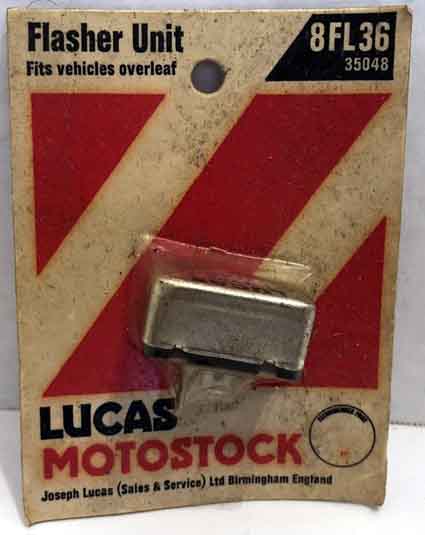
An NOS Lucas 8FL Type 36 35048 unit (so correct for the MGB) that comes up on eBay from time to time and gave a faster and more consistent flash rate:
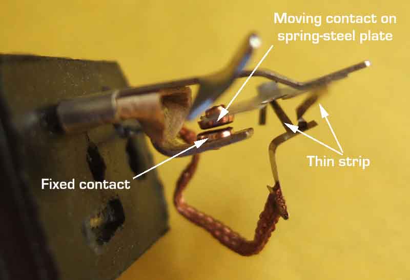
Guts of the 2-pin indicator unit with main features labelled:
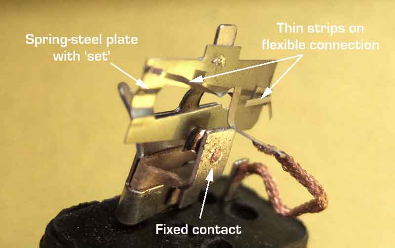
Showing the contacts, which would normally be closed on a working unit (this is a failed unit). There is a very low resistance path from the battery through the thin strip and closed contact in series with the indicator bulbs, so the bulbs light immediately the indicator switch is operated. The current through the thin strip heats it, it expands, and allows the spring-steel plate to take up its normal set. This opens the contact, which cuts off current flow through the lamps and the thin strip. The thin strip cools, contracts, and pulls the spring-steel plate back onto the fixed contact again, and the unit starts clicking 'off-on-off-on'. This type of unit is very susceptible to current flow. With one indicator bulb failed the current is halved, ditto the heating effect, and so the contact fails to open. But this gives a clear indication of a problem and easy diagnosis (at least of which corner the problem lies) since the working lamp remains glowing. However it is so sensitive to current that it doesn't take much of a drop in voltage (i.e. lots of electrical things switched on) or current (i.e. a few slightly high resistance connections) for the unit to start flashing slower or not at all even though both corners are lit:
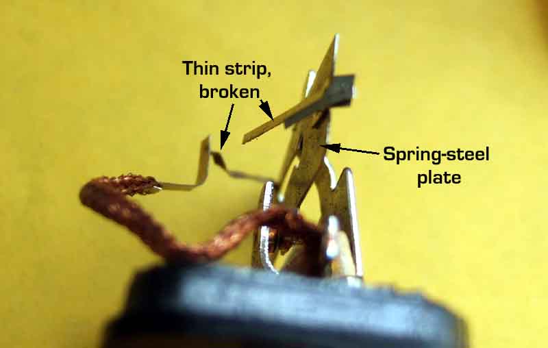
This particular example had failed. When the case was removed it was apparent that the thin strip had broken such that the steel plate was no longer pulled back against its set, so the contact was open all the time:

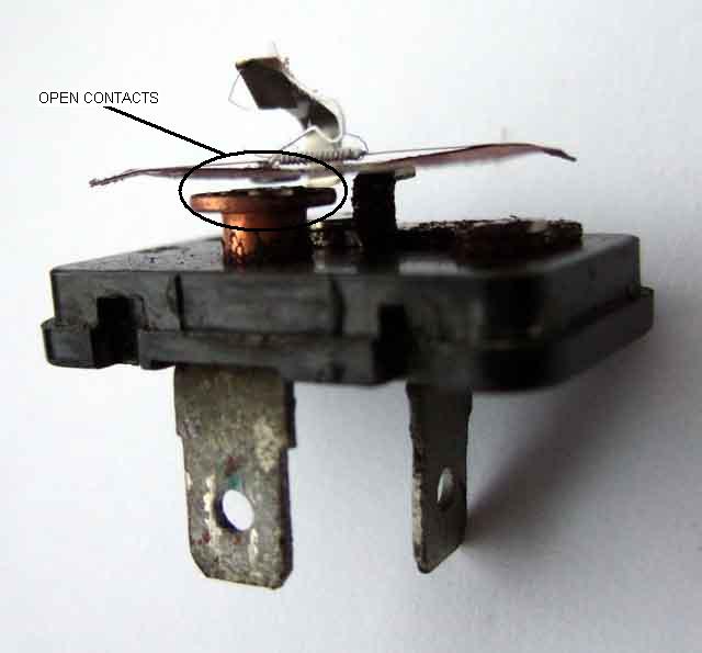
Lucas hazard flasher showing the heating element running diagonally across the bi-metallic strip with additional resistance wire wrapped round the element:
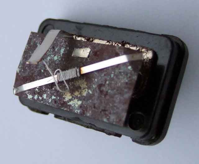
Showing the normally-open contacts. Because hazard flashers are designed to flash at a relatively constant rate, no matter how many bulbs are left working after say an accident, and with falling battery voltage from being left flashing for a long time, they are designed differently to indicator flashers. The heating element is connected across the open contacts and is operated by the 12v supply, is too high a resistance to make the lamps glow, and the current through it barely alters regardless of how many bulbs are connected - as long as at least one is working. When the element has heated the bimetallic strip the contact pings closed which shorts out the heating element and lights the lamps. With the heating element shorted out it starts cooling down, the contacts ping open which turns off the lamps and connects 12v to the heating element again to repeat the process, and the unit starts clicking 'on-off-on-off':