
Having acquired a 4 speed non o/d gearbox, I was able to dismantle it. It was purely for interest and to "see how it works". It turned out to be in excellent condition, so I did not remove the various components from the shafts.. The key difference between this and an o/d box is the mainshaft, plus a few bits and pieces. O/D mainshafts are NLA (as are some parts) so it may prove more economical to source a recon box.
The workshop manual and Haynes are fairly good, but the following may help also. The "books" also give information as to clearances and checking for wear.
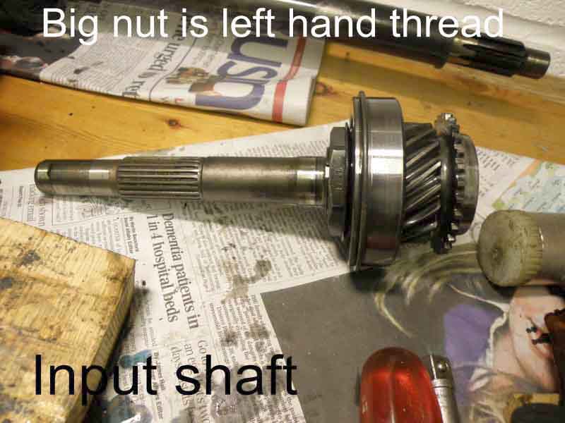
You will need to remove the "big nut" at the end on the mainshaft. It is probably worth doing this right at the start.
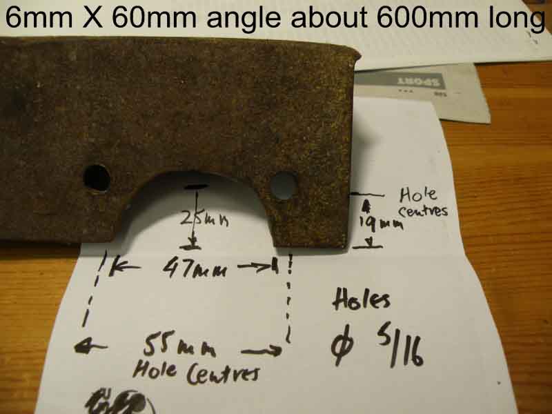
You need a piece of 6mm angle iron, about 2 foot long, with a suitable sized "bite" out of one end and two holes. The bite is large enough to fit the 1 5/16" AF socket and the holes line up with 2 adjacent bolts on the flange. I was lucky in that when bolted up, the angle iron rested against the leg of the bench, so I tied it to the leg and used a 2 ft breaker bar to undo the nut. It might be easier to leave the gearbox on the floor to allow it's own weight to help with undoing the nut.
(See also this 'universal' tool made from B&Q flat steel strip).
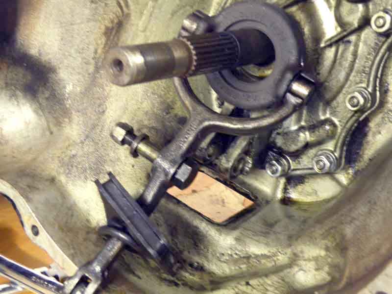
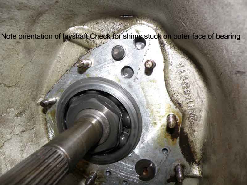
Gearbox input shaft - release bearing inadvertently rotated through 180 degrees.
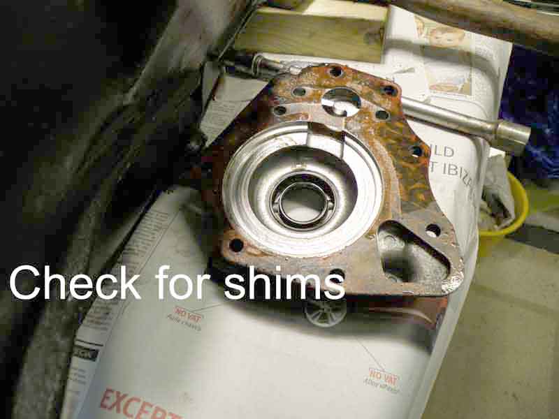
Front plate removed.
Check for shims in front plate.
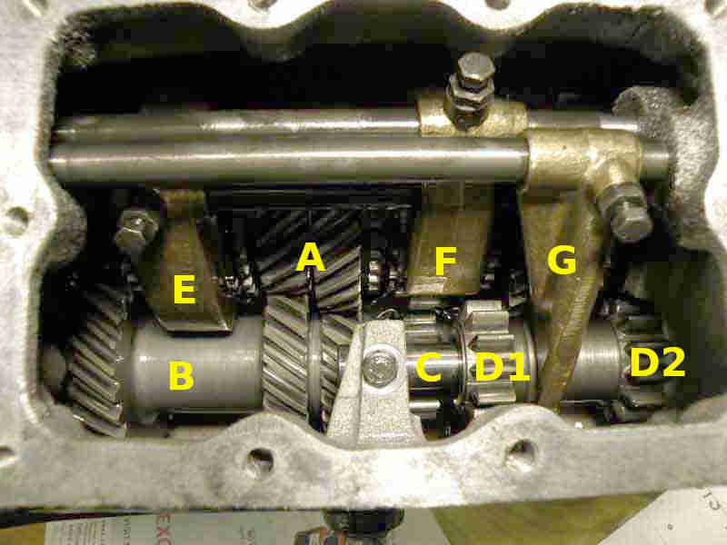
What lies inside: 'A' 3rd (left) and 2nd (right) gears on mainshaft; 'B' Laygear; 'C' reverse idler gear shaft; 'D1' driven gear on reverse idler; 'D2' driving gear on reverse idler; 'E' 4/3 gear selector fork; 'F' 2/1 gear selector fork; 'G' reverse gear selector fork:
I found removing the interlock plate impossible until I moved the gear selector lever out of the way by selecting third (I think) gear.
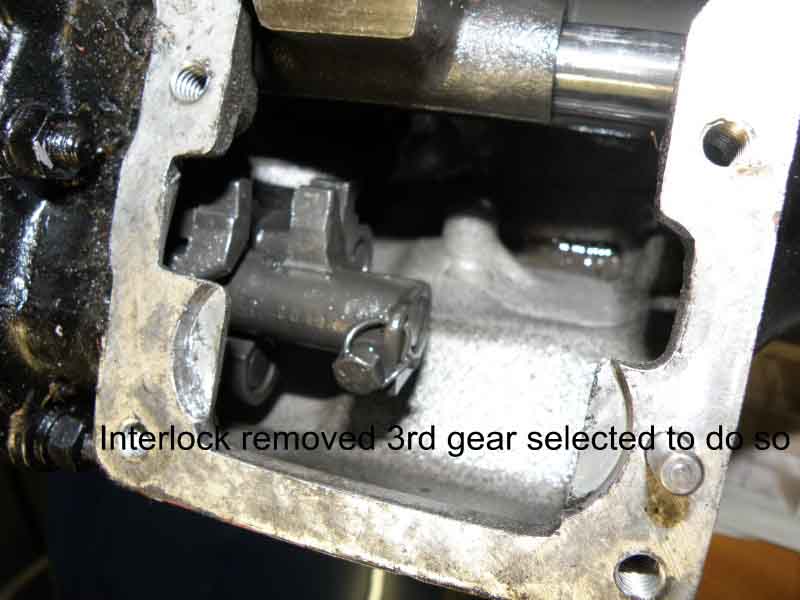
It's a fiddle and perseverance is needed! I used a socket on the end of an extension as a makeshift gear stick located in the hole. The plastic grommet had remained in place on the remote control shaft.
You now have the gearbox in a more manageable state-without the remote cover and the tail-just the mainshaft sticking out. Remove the selector rods and forks as described in Haynes. Check the clearances for the laygears.
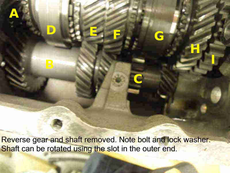
'A' mainshaft gear driving the laygear and dog-clutch for 4th gear; 'B' laygear; 'C' laygear teeth to drive the reverse idler gear (reverse gear and shaft removed); 'D' 4/3 synchroniser and selector; 'E' 3rd gear on mainshaft; 'F' 2nd gear on mainshaft; 'G' 2/1 synchroniser and selector; 'H' 1st gear on mainshaft; 'I' reverse gear on mainshaft:

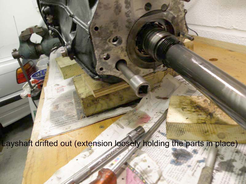
Next to drift the layshaft out. You need a long drift and a piece of coat-hanger wire. As you drift out the shaft push the wire (not shown) down the centre to keep the thrust washers roughly in place. Allow/assist the laygears to move to the bottom of the casing.
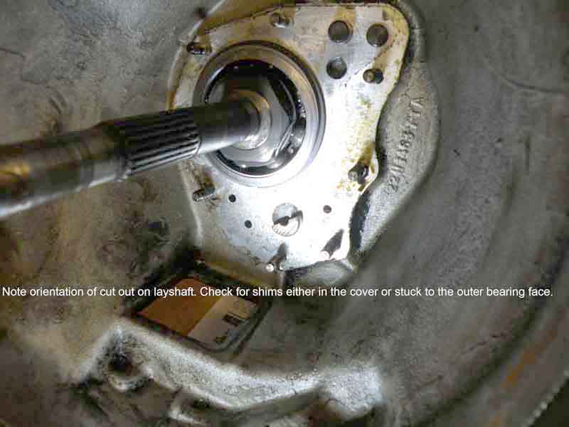
I managed to remove the mainshaft whilst the box was horizontal-it slid out easily- note the cut-out in the bearing housing. It might be necessary to put the box bellhousing on the floor (on blocks) and tap the rear of the casing to free the mainshaft. In this case ensure the laygears are out of the way, as being vertical, they can move across and jam the mainshaft. Inspect the mainshaft clearances.
Output/mainshaft with the '4/3' synchro assembly moving left for 4th and right for 3rd, ditto the '2/1' assembly, and near-equal 1st and reverse gears. 'A' is the needle roller that engages in the end of the 1st-motion shaft to support that end of the mainshaft, 'B' is the worm gear for the speedo drive:
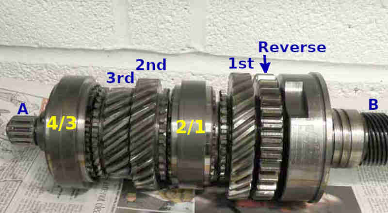
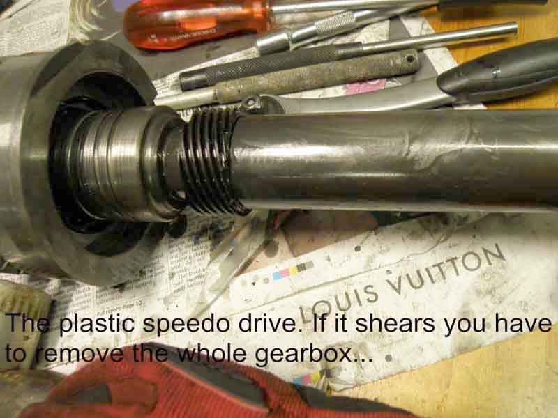
Take care not to damage the plastic speedo gear.
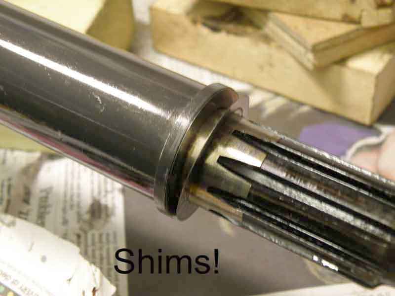
More shims on the mainshaft.
To remove the input shaft you need to use a (softish) drift on the outer bearing face from inside the box. It takes time and patience as the angle is not easy!
It's now apart!
To re-assemble........I put the box on blocks on the floor to drift the input shaft assembly back in. Again a softish drift is called for but as it refused to go in, I finally resorted to a 4 ft long steel bar and the wheel spinner hammer, but keep it on the outer bearing casing. Just tap round and round till it goes in! Check the needle roller bearing is either on the mainshaft or the inner end of the input shaft-doubtful! Rest the bell-housing end on blocks on the floor and ease the mainshaft in (note cut-out in bearing housing). It will need jiggling as 2 sets of splines must engage. An assistant is useful in ensuring the laygears are kept out of the way. Once the mainshaft is in, move the laygear assembly till in "engages", find a piece of 20mm electrical conduit or similar, and insert this over the coat-hanger wire to reposition the laygears and thrust washers more centrally. Replace on the bench. Clean the layshaft and check for any burrs or damage. Attach a bungee cord or rubber bands to the end of the electrical conduit at the tail, sufficient for it to be taut enough to keep the end of the conduit against the end of the shaft as it is drifted in. Alternatively an assistant can keep pressure on the tube. Drift the layshaft in from the bell-housing end taking care that the orientation of the cut-out matches that of the front cover (you can use mole grips to rotate it once it is inserted).
Squirt some oil on to the cogs and up the oilway on the ends of the layshaft, and twiddle the input shaft.
Slide the selector rods in through the forks. Note that the rods have holes in which the bolts bolt into. A delicate touch whilst finger tightening these bolts and moving the rod very slightly will ensure the bolts are in the right place. I got it wrong and caused the "fingers" (that protrude out of the tail) to jam.
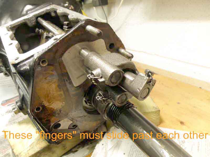
Once I rotated the shaft a tad the bolt in the fork engaged properly and the "fingers" slid past each other. Now slide the tail on having first replaced the gasket, and bolt up. Engage 3rd (I think) gear to allow the interlock to be inserted. Feed it in rounded end (not the finger end)first as far as possible in a diagonal direction. Then rotate it and move it slightly left to allow the flat plate to sit in the recesses. Again a fiddle-at first it seems impossible and when it finally slips in, you wonder how you did it! Bolt the remote casing back on, squirt some oil on the cogs, bearings, and replace the side, and front covers. I was storing mine so just used enough to keep moisture at bay. If replacing in the car I would add more to allow for initial lubrication.
© Copyright Michael Beswick 2013.