Clearance to wheel weights
Compensator
Adjuster
Cable Length:
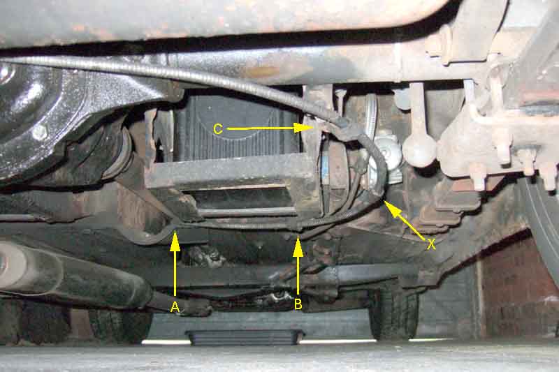
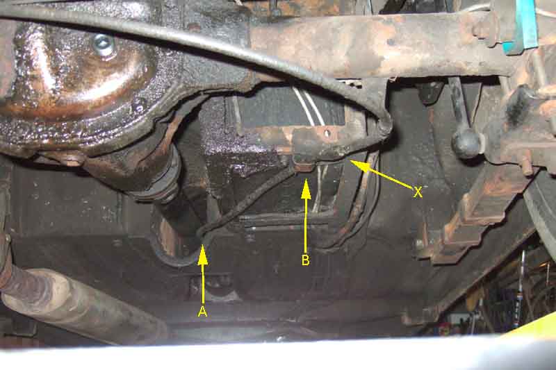
Early rubber bumper exits in the same place but only one mounting point B and the cables are about 8" shorter. This would put the grease nipple much further underneath the car, but originally they didn't have one. This is the longer CB cable on an RB car so makes the routing less than ideal and puts the grease nipple further away, and the longer cable can flap and hit the tank. Now I've discovered the difference I'll probably reposition the existing bracket as per the CB car and add the second bracket, which should make the grease nipple more accessible as well support the cable better. It can easily be reversed as and when I need to fit a pukka RB cable.
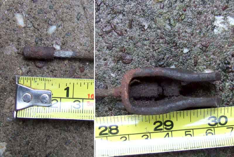
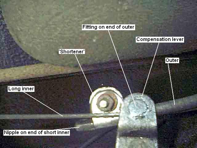
An old stud-wheel cable measuring 30" from the tip of the nipple in the short cable at the compensation lever end, to the tip of the U-clip that attaches to the lever sticking out from the back-plate. A new, almost certainly wire-wheel axle cable measures 28.5" here.
A 1" 'shortener' fitted between the nipple and the fitting on the end of the outer sheath at the compensation lever
Clearance to wheel weights:
The cable and lever should not project past the edge of the brake drum:
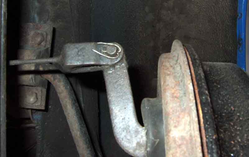
Leaving plenty of clearance - at least 1/2" - for stick-on wheel weights:
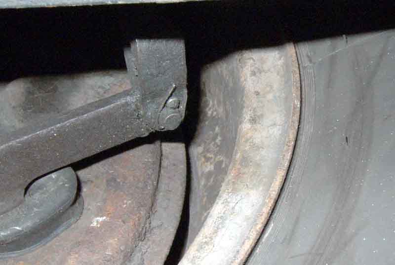
Vee ditto, with shortener hence the compensator points more towards the off-side ... somewhat muckier than when first fitted:
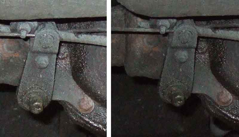
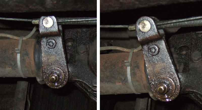
Decades later and I've just noticed that Vee's cable trunnion is the other way round to Bee's, putting the end of the outer away from the viewer on Bee and towards the viewer on Vee - I've changed both at various times. Pictures elsewhere show it both ways, but as Vee it allows the outer to drop away from the short cable as it goes under axle, whereas the other way round they can rub together.
Compensator components as shown by Moss Europe (Brown & Gammons and the Leyland Parts catalogue drawings omit several washers). The two halves of the compensator lever 43 and 44 are clamped together by the screw, lock-washer and nut 52, 53 and 54 around the trunnion (shown faintly between 43 and 44 and should be free to pivot) on the cable outer at one end, with bush 45 at the other end of the two halves. This assembly should then pivot freely on the 'link-pin' 46 when the stiff-nuts 47 and 51 have been tightened:
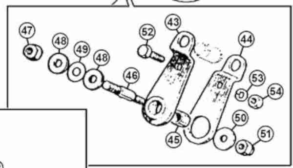
Not even that shows the full story though as using the key and part numbers the parts are shown in the wrong places. The larger thread on the link-pin screws screws into the diff bracket positioned at 'A' the plain section flush to the bracket, with the larger 3/8" stiff-nut LNZ106 behind it as a lock-nut. One of the larger 7/16" plain washers GHR303 has been slid onto the link-pin ready for the lever assembly and bush which goes on next at 'B'. Then the 7/16" crinkle washer AWZ107 and other 7/16" plain washer go on the plain section of the link pin, then the 5/16" plain washer PWZ205 butts up against the shoulder on the pin, and finally the 5/16" stiff-nut LNZ105:
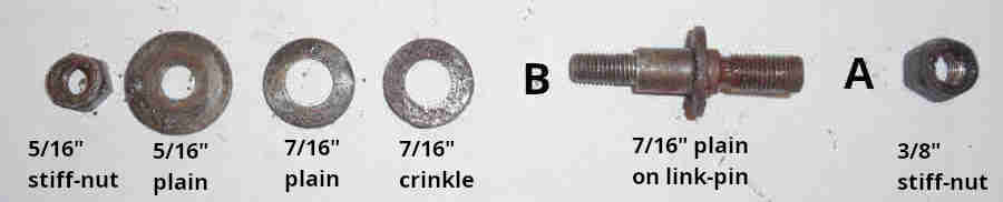
If the 7/16" washers are too thick, or a 7/16" washer is used in the outer position in place of a 5/16", tightening the nuts will quite likely jam the compensator lever in position preventing the off-side wheel being braked by the handbrake, or even worse locking it on. If slackening the visible nut frees the compensator up then that is what has happened. The same will happen if the compensator bush is seized to the link pin, but in that case only if the nut behind the bracket is left slack will the compensator be free to move, which allows the link pin to wobble about in the bracket wearing both parts.
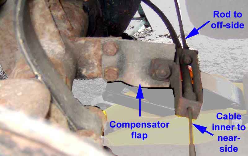
Showing the rubber flap attached to a flange on the axle casing, to which a bracket on the handbrake cable is attached. The rear pivot and mounting for the anti-roll bar can be seen on top of the axle casing (top left), but other than both being attached to the tube in adjacent areas the two are entirely separate.
Showing the rear of the diff, where the handbrake pivot used to be, with the anti-roll bar well out of the way.
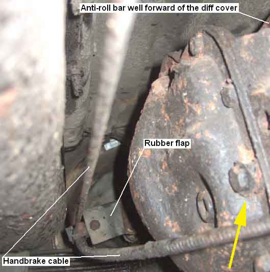
November 2016: It was only when someone asked a question about an additional support for this cable that I realised something is missing from my pal's car. There should be a rubber strap (BHH2136) through which the cable passes, attached to the diff cover bolt to the right of the level/filler plug in the above image, and indeed there does seem to be the spacer and remains of the strap under the bolt (arrowed). The Moss Europe image below shows how it is used (item 59). This strap deteriorates rapidly and apart from the bit under the bolt and washer may well vanish. Lack of it does not affect handbrake operation, but may allow the cable to rattle against the axle.
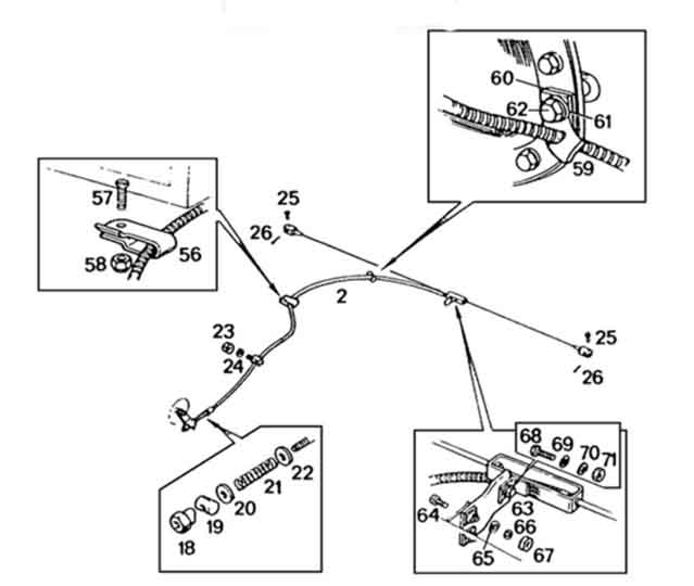
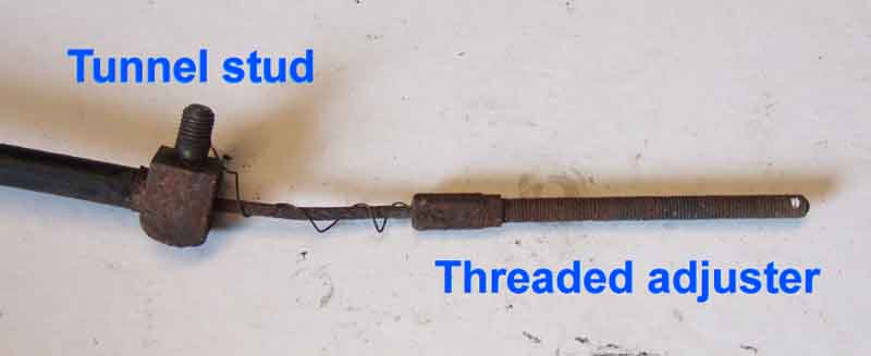
The strap has a cut from the middle-sized hole for the cable towards the large hole for the fixing bolt, ending at a small hole, and this slot should enable the cabin lever end of the cable with the tunnel stud on the outer to be passed through for retrospective fitting. However that does need the cable to be disconnected from the cabin lever and tunnel, and the support under the battery box, to fit from that end: Motaclan/Leacy

I've seen claims that the strap can be fitted over the 'box' that is at the end of the outer which needs the near-side clevis pin to be disconnected as well as the screw between the box and the flap. It's also going to be a bit of stretch to get the box with its tab for the compensator flap through the cut in the strap. I've also seen a claim that the box doesn't always have the tab that attaches to the compensation flap, or the flap on the axle, but that seems unlikely as it would mean the cable is unsupported at that point, other than from the strap, which would be subjected to the cable flapping up and down when under-way. And when the strap fails - which they do and was what started off the thread on the MG Enthusiasts forum - the majority of the cable will be unsupported and flapping up and down.
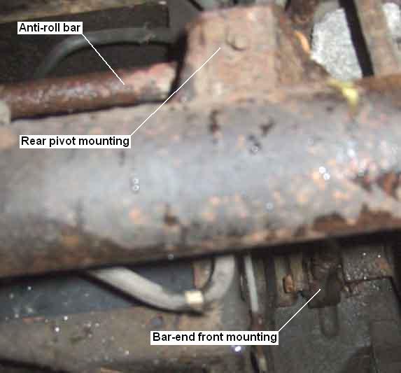
Showing the anti-roll bar, rear pivot on the axle casing, and front pivot mounting point on the body.
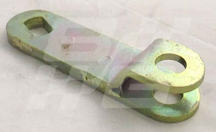
The handbrake assembly has a lever (BHH1469) in the tunnel that is similar to the compensation lever on the diff casing, but the two halves are welded together: (Brown & Gammons)
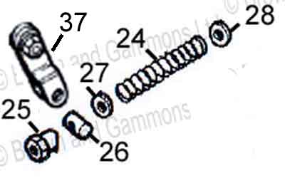
Trunnion AHH5322 (left) and brass adjuster nut ACH5104: (Motaclan/Leacy)
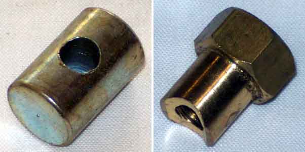
The trunnion (26) fits in the two holes of the handbrake lever (37) (it can fall out when removing or refitting the cable and roll some distance!), the threaded section of the cable fitted with a 1/4" x 3/4" washer (28), an expanded spring (24) and another washer (27) is passed through the fitted trunnion, and finally the adjuster nut (25) is screwed on: (Brown & Gammons)