
by Herb Adler 5243 3409
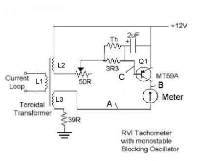
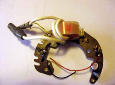
I recently had a need to check on the operation of one of these tachos, and luckily I had one disembowelled on the bench. This type of tacho has the internal toroidal transformer as the trigger sensor. Below are a picture of the circuit board, the circuit diagram and waveforms.
 Function:
The circuit is what is called a monostable blocking oscillator. What this means is that there is only one stable state, no pulse, and until a trigger occurs the transistor Q1 is blocked from turning ON.
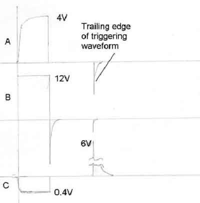
This transistor, Q1, acts as a switch, i.e. it is either ON or OFF, as can be seen at waveform B, where Q1 turns ON and the voltage goes to 12V and then it turns OFF and the voltage goes to 0V.
L1,2 &3 are windings on a toroidal (circular) transformer, the plastic encased red thing with the white wire wrapped a couple of times around it.
L1 is the current sensing/triggering winding, the heavy white wire, that has the ignition coil current passing through it.
When the points close and current flows through the ignition coil, and L1, then a voltage is induced in L2 & 3.
The L2 voltage is the control voltage for Q1, turning it ON, with a voltage, as shown in waveform C.
Whilst this C voltage is present Q1 is ON. With Q1 ON current flows through the meter, giving a deflection/reading, and repetitive pulses are averaged by the mechanical inertia of the meter, which gives a "steady" reading, proportional to the engine revs.
As current through a coil cannot change instantaneously there is a gradual build up of current and thus voltage, in L3, as shown by waveform A, creating an increasing magnetic field. Because there is a changing magnetic field, due to the increasing current, coil L2 has a current / voltage induced in it, which keeps Q1 turned ON.
When the transformer's core saturates, i.e. any more current will not produce any change in magnetic field, the voltage induced in L2 stops, and Q1 turns OFF. This action makes the transformer the main timing element.
The energy stored in the core of the transformer is released as the big spike at the end of the pulse, as shown in waveform B.
The 3R3 ohm resistor and the thermistor (temperature sensitive resistor) Th, are a temperature compensation network, to minimise the effects of temperature on the operation.
The 2uF capacitor, I think, should absorb the 6V spike, seen well after the completion of the pulse cycle, and is the end of current flowing into the ignition coil, i.e. when the points open. The reason this 6V pulse is there, in my opinion, is that the capacitor, in my unit, is 30 plus years old and has ceased functioning. Removing it from the circuit made absolutely no difference, a test done for other reasons.
The variable resistor of 50R ohms, is there to allow calibration of the readout to the engine revs, and it does this as the pulse width is determined by the relationship of the inductance of the transformer divided by the circuit resistance. A wider pulse gives a higher reading, as do more pulses, at higher revs.