
Hover over a wire to confirm the colour

Note 1: Up to 1970 the heater fan was powered from the green circuit in the fusebox. From 1971 for the remainder of chrome bumper production and all V8s the heater fan (and wipers and electric washers) were powered from the accessories position of the ignition switch via a white/green to an in-line fuse under the fusebox, and then via a green/pink to the fan switch. 4-cylinder rubber bumper cars up to the 1977 model year were powered from the green circuit in the fusebox again.
Note 2: Before 1970 the wire from the switch to the motor was Green with a Brown tracer. From 1970 it was Green with a Yellow tracer.
Note 3: Up to October 64 the wires going into the fan motor may both have been black. Because of the 2-way bullet connectors these can be connected either way round and should make no difference. The later fan motor with the differently coloured wires gives a vastly superior performance one way round compared to the other, try both ways.
Note 4: The single-speed fans on my 73 and 75 take about 3 amps.

Note 1: On 1977 models the heater fan is powered from the green circuit in the fusebox off the ignition relay, but when the ignition relay circuit on RHD cars was modified sometime in 1978 a second in-line fuse between brown/white and green wires was added under the fusebox. The heater fan (together with indicators and GT HRW) was powered from one of these - the one with the thinner wires, the other with thick wires being for the cooling fan.
Note 2: If installing an uprated or aftermarket dual-speed motor that has three terminals to give the two speeds, care must be taken with the switching that power is not applied to both live motor terminals at the same time, or the motor will be damaged. This does not occur with the original two-speed system that used a single-speed motor and additional dropper resistor as shown above.
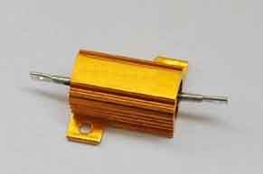
I didn't know the actual resistance and wattage values of the dropper resistor, but did some tests to see what sort of values they might be. I put a standard 3 ohm coil in series with the motor and it seemed to drop the speed by about half which would be about right. I then measured the voltage across it with the motor running at this speed and got about 5v, which at a system voltage of 12v (engine not running) is about half voltage which tends to confirm what I'd heard. This represents about 1.7 amps (voltage across the resistor divided by its resistance). Subsequently the manufacturer of the heater systems for the MGB and many other makes and models, Ashley Hinton, told me that they were 2.5 ohms so not a bad guess. Based on my test the motor has an equivalent 'resistance' of about 4 ohms, so with a 2.5 ohm resistor you would get about 2.2 amps, so about 5.5v across the resistor. Wattage is calculated by squaring the voltage and dividing by the resistance i.e. 5.5x5.5/2.53 which gives 12 watts. If you want to convert a single-speed system to a 2-speed the resistor would need to be greater than 12w to avoid burning it out, and probably screwed to a metal mass to aid cooling, making this type the best bet.
If you have a 2-speed you can measure the resistance by putting an ohmmeter between the green/yellow and green/brown wires with the fan switched off, and measure the voltage across the resistor by putting a voltmeter between those two wires with the ignition on and the fan switched to slow.
You can only calculate watts by measuring the actual resistance of and voltage across the resistor in this way as motor current varies with rotational speed, a stalled motor taking a lot more current than a freely running one. You can't measure the resistance of a stationary motor and use that in any calculations, except to see what the stalled current would be.