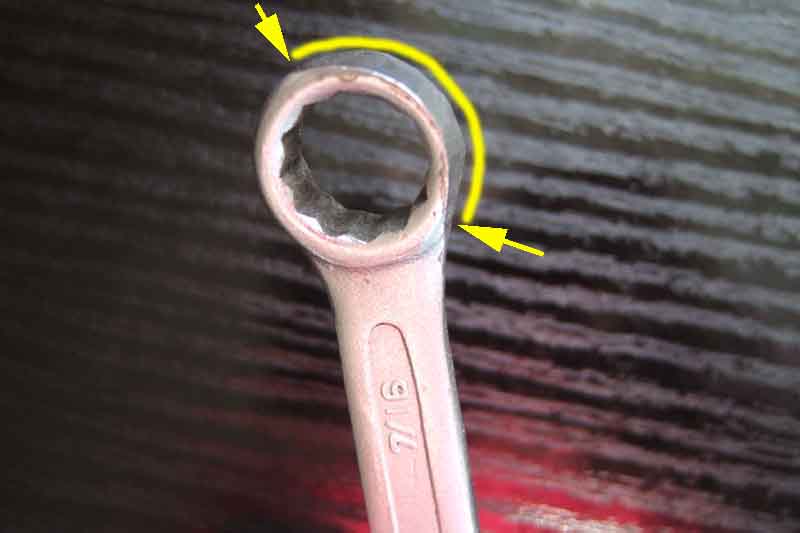
Ring-spanner modified by grinding away part of the ring to be able to fit the bolt heads with replacement valves:
Door handle spindle (7mm or 8mm will suit) with 1/4" drive 7/16" socket:
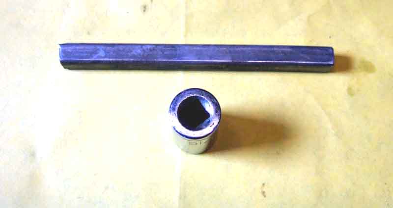
Bent to shape:
Filed to size and cut to length:
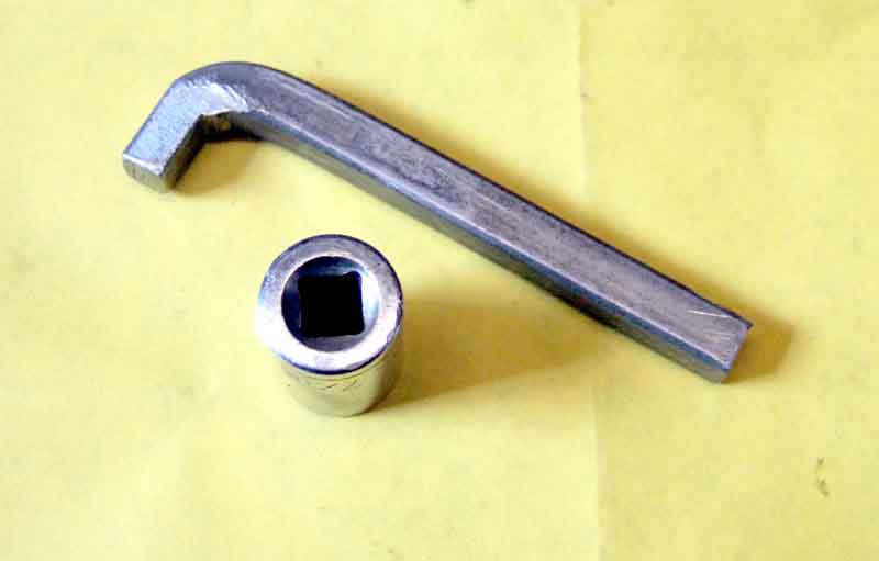
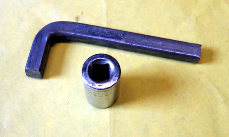
Fitted to socket (also suitable for seat runner stop blocks):
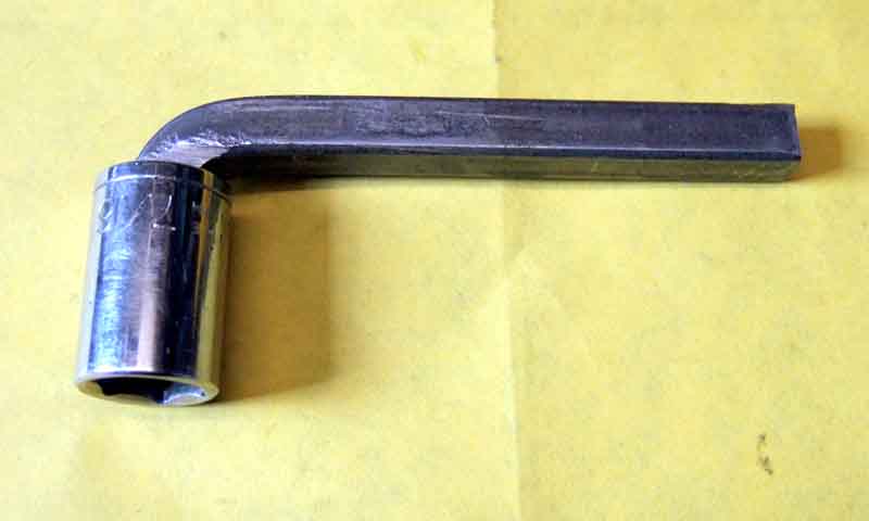
Just the job:
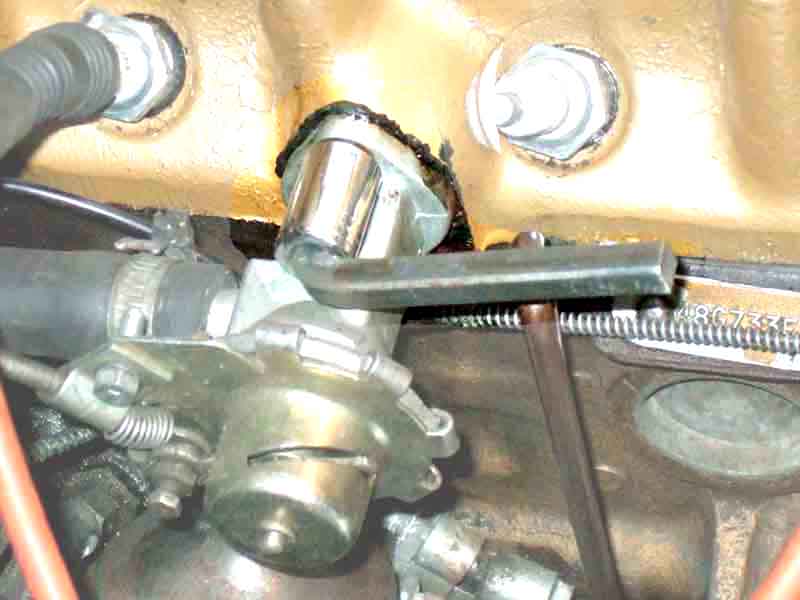
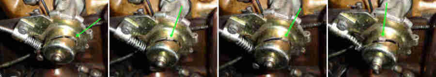
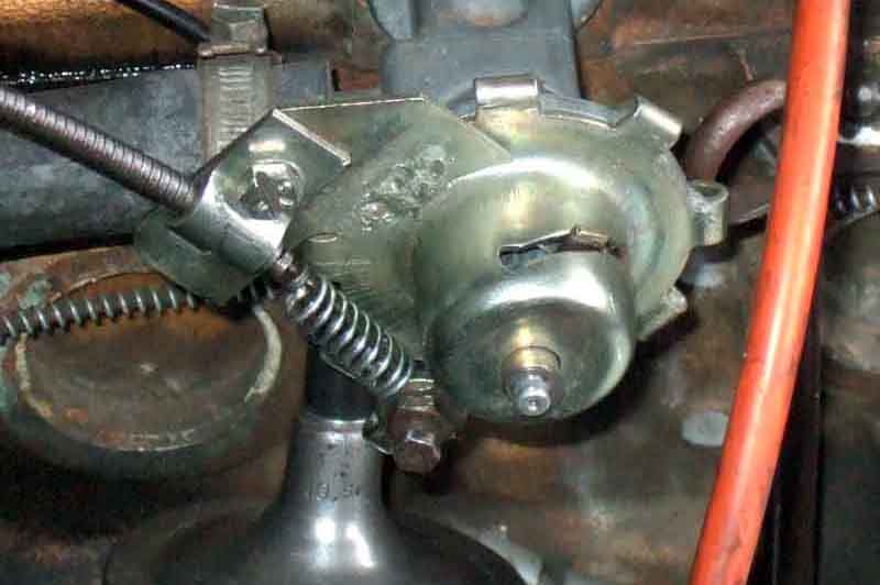
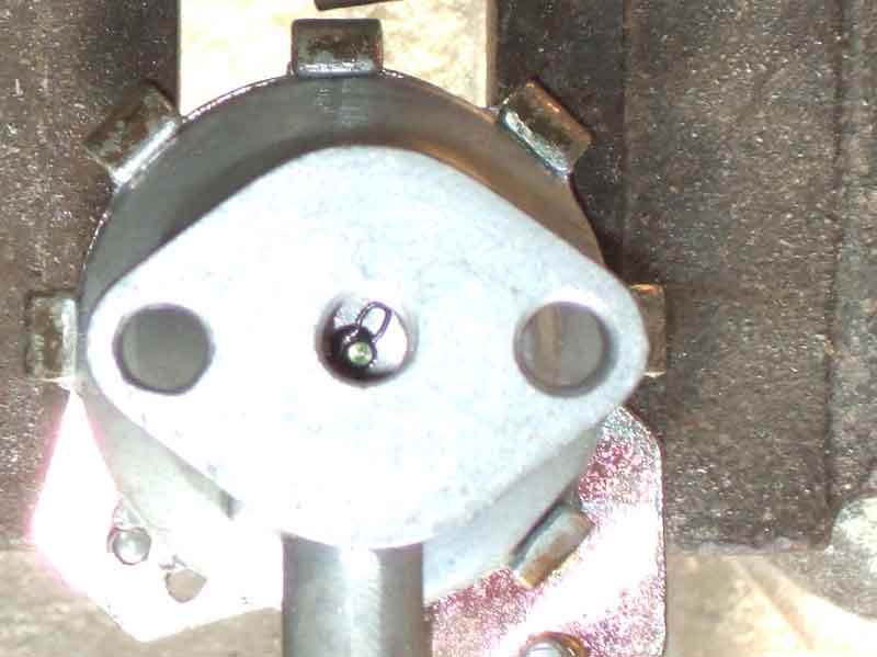
Marks showing the fully open (from a maximum flow point of view) and fully closed points of Michael Beswick's new valve:
Possible 'summer' and 'winter' settings - 'summer off' on the left, then 'summer on', then 'winter off' and lastly 'winter on' on the right. However as previously said the valve has to be moved quite a bit towards 'off' before the heat from the vents starts to reduce:
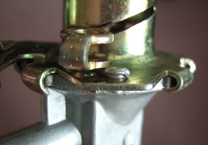
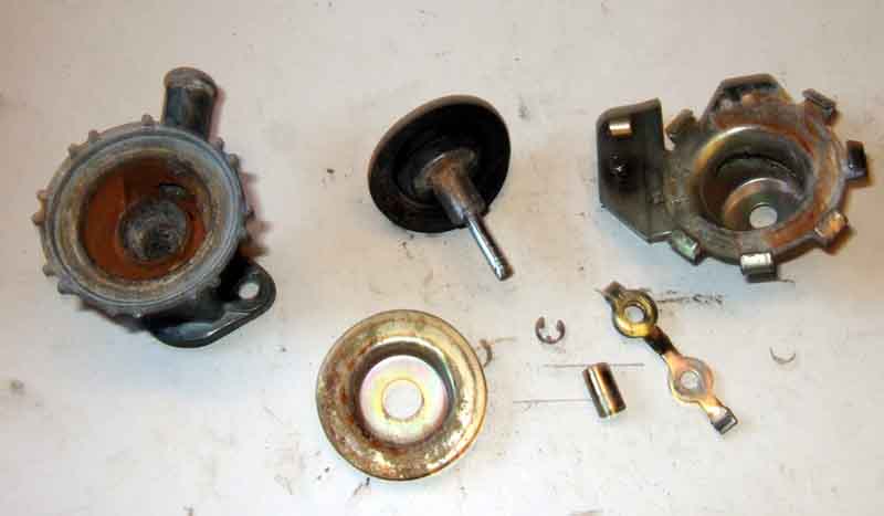
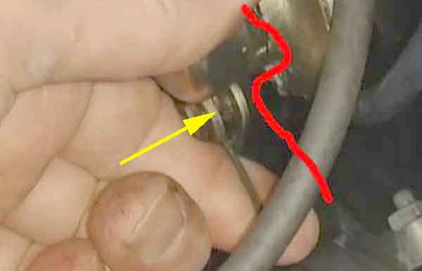
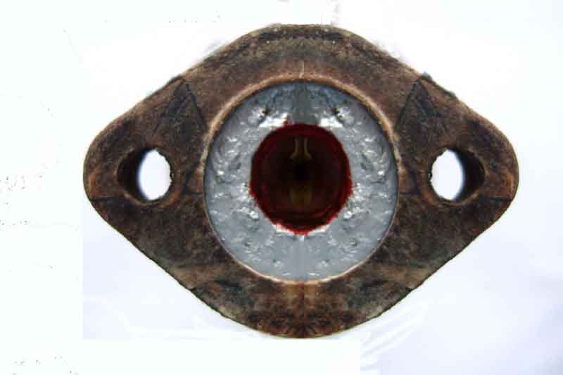
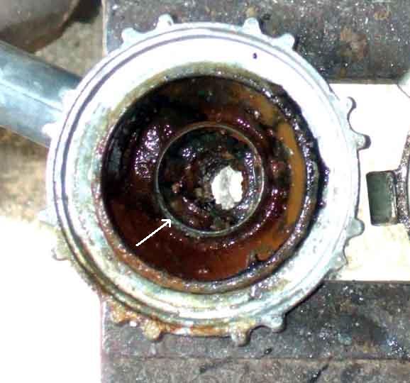
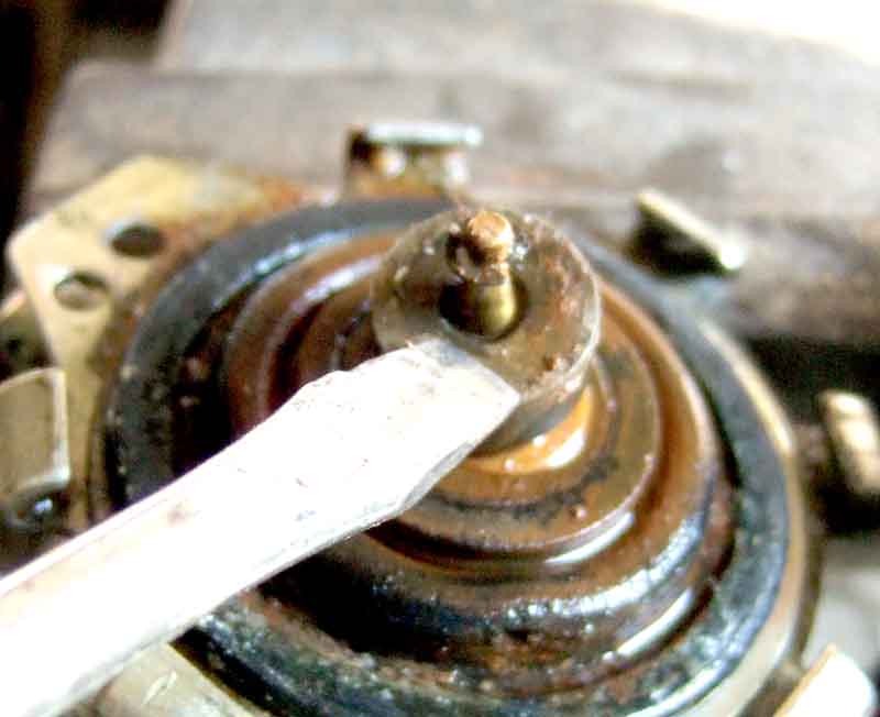
If you look at Bob's drawings he depicts his pin as straight and fairly close-fitting through the centre of his cup, whereas the picture below shows my pin is tapered, and the hole in the centre of my cup (yellow and partly cut away in the inset) is much bigger. No circlip was fitted to my pin, it may have corroded away, certainly the cup and its seat were quite heavily corroded. It doesn't seem to need a circlip, the spring is a push-fit onto the diaphragm and into the cup and so lifts the cup off its seat as the valve is opened more than half-way. The pressure of coolant flow from the water pump will also tend to open the coarse-control valve as spring pressure is relaxed:
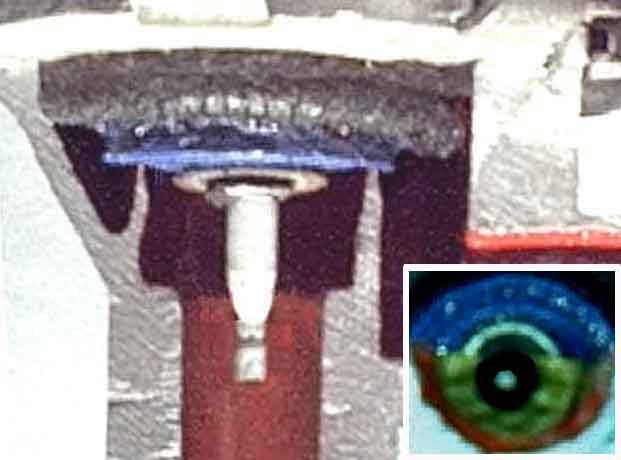
The first stage is the rubber diaphragm (blue in the picture below) which presses down on the end of the 'pipe' the cup sits in, to completely prevent any flow - the shut-off. As well as this the cup is sitting on its seat (coarse control) and the widest part of the pin is in the hole in the cup (fine control):
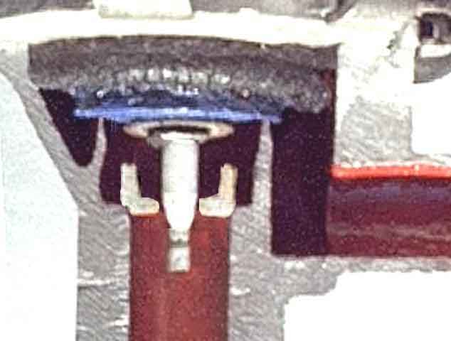
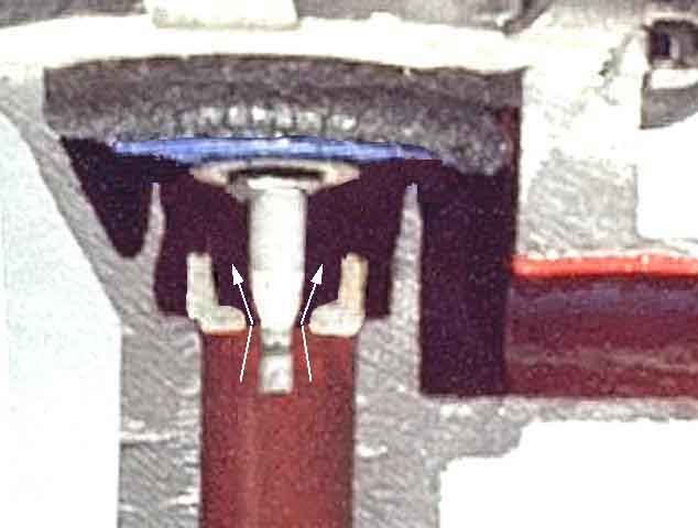
As the valve begins to open the blue diaphragm lifts off its seat opening the shut-off, but the cup remains on its seat so the coarse-control valve is still closed. As the pin, attached to the diaphragm, rises through the cup the taper narrows giving a very gradual increase in flow through the valve. This image shows the valve about half open (operating lever about mid-way in its travel) with the fine control fully open but the coarse control still closed:
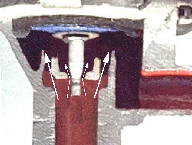
The third stage is where the valve opens sufficiently to lift the cup off its seat and coolant begins to flow past it giving a rapid increase in flow - the coarse control. The fine-control valve is still fully open and the diaphragm valve is now fully open and the maximum flow is passing through the valve:
If you imagine that that coolant only flows past the raised cup and not through its middle then you would be right in thinking that the first half of valve travel, whilst opening the shut-off valve, does not allow any coolant flow and so is wasted movement, plus the valve won't open as far as it could. Adding washers will cause the pin to start lifting the cup valve off its seat almost as soon as the diaphragm starts moving and so give earlier flow as well as a greater maximum flow, but the washers will block the fine-control valve altogether which will result in there being very little control movement between OFF and HOT i.e. no WARM. Someone else has also opined that if the corroding away of the circlip is not uncommon you wouldn't want a bunch of washers circulating round your engine:
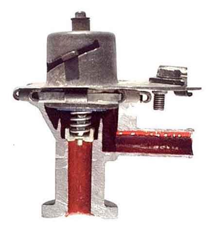
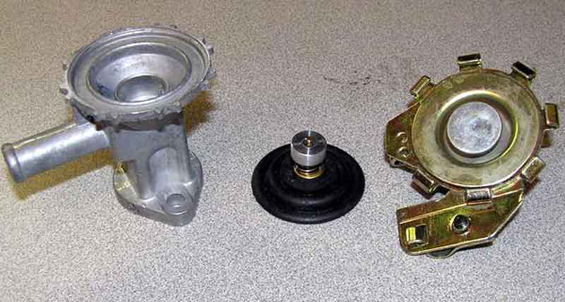
Kelvin Dodd of Moss Motors (USA) has posted this picture of a dismantled valve:
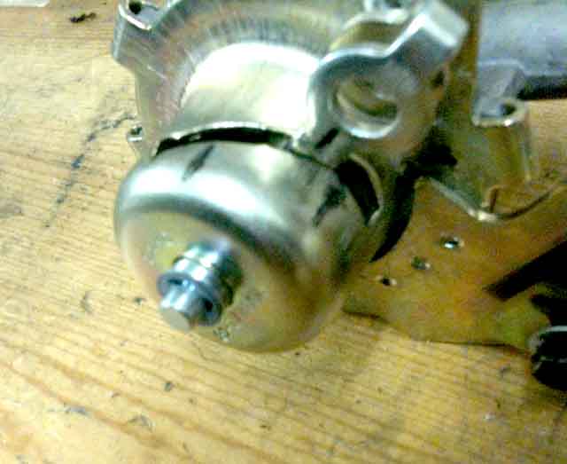
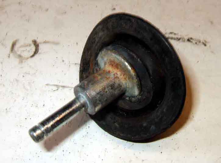
My most recent failure dismantled, the diaphragm is very securely attached to the spindle, not separate as Kelvin shows:
A flange on the end of the spindle fits into a cavity in the diaphragm - partially removed:
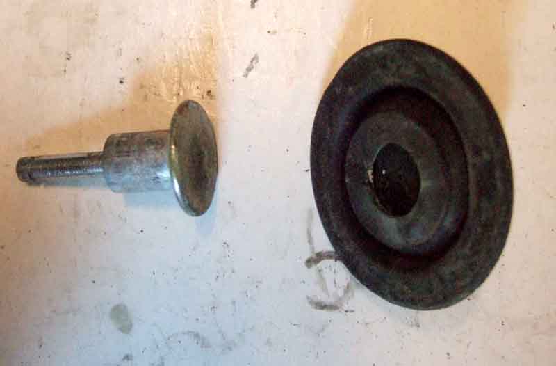
Fully removed:
Kelvin was of the opinion that failures from leakage could be due to the closed valve pushing the diaphragm tightly onto the seat, it sticking there, to be ripped as the valve was opened. But as Kelvin shows it that cannot happen if the diaphragm is not attached to the spindle. I had to fully dismantle the upper part of the valve and lever the spindle flange out of the diaphragm as it was tightly fitted. Maybe Kelvin's being new and perhaps softer rubber it pulled apart without the extra dismantling. But even then unless the diaphragm rips right through at the seat, and that is the thickest part, it would not leak, and mine have split in the bellows section between the seat and where it is clamped to the casting.
A 'push-off' spring on the cable between the outer and inner clamps. This is nearly fully compressed when the valve is closed ...

... and taking up about 4/5ths of the space when the valve is open. If the spring were stretched out to have a longer free length then it may well push the valve open even more. Some people get hot under the collar (boom boom) about getting the valve fully open, but on both my cars you have to close the heat control beyond WARM i.e. more than half-way before getting any noticeable reduction in heat output so I really don't think it is necessary:
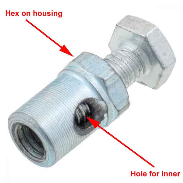
The two pictures above show the correct trunnion, but here a different type has been used with a clamping nut which has allowed the whole thing to turn while tightening the nut so bending the solid inner wires into an 'S' shape. It's just possible to see (arrow) how the inner is bent at a 90 degree angle to go down through the hole in the trunnion, then bent back up at another 90 degree angle underneath, as the red line depicts. This prevents the inner from being removed: (Bill Etter)
Trunnion kit 24G1482K should be used in this position, the hex on the body allows it to be held still while tightening the screw, which will prevent the inner being bent into that 'S' shape: (Moss Europe)
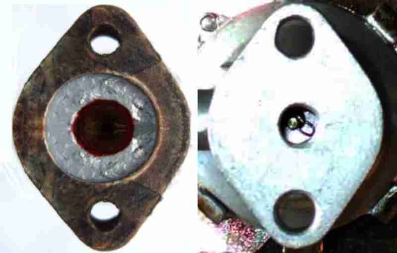
The correct gasket laid over the flange on the heater valve. The hole in the gasket is about the same size as that in the head, with that in the heater flange being very much smaller. This greatly reduces the available area to clamp the gasket and form a good seal. It also allows corrosion to develop on the face of the heater flange which can 'burrow' under through what clamping area there is to cause a leak:
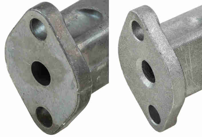
The inlet port on the replacements that have been available for some years has got noticeably smaller when compared to an original that had inlet and outlet the same size, as well as the body getting fatter so you can't get a ring spanner on the screw heads:
Moss Europe show two 4-cylinder valves one with the original part number (£18, left) and one classed as 'aftermarket' with a Z suffix (£15 right), the difference seeming to be that the aftermarket has a chamfered inlet, and maybe a rougher texture:
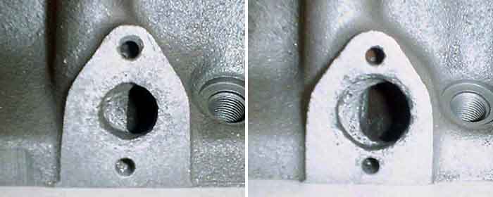
Heater ports in 'early' (left) and later (right) heads, from Sean Brown's Flowspeed.com. Sean dates the change to the 12H-2923 head introduced in 1972. British Automotive agrees and says they were fitted to 18V584/585/672/673 engines, although Clausager dates those engines to August 1971 i.e. the start of the 1972 model year. Both the above web sites refer to North American engines only, although the Non-NA 18V581/582/583 engines were brought in at the same time, Clausager lumps all the 18V58n engines together so one can assume UK engines are the same. My 1973-model 18V582 is like that, although it is a Gold Seal replacement engine (albeit the correct equivalent) so could have a later head anyway. Sean Brown attributes the change to making it easier to remove casting sand. As far as I know only the 'later' gasket with the large hole (12H3868) is available, indeed that is the only one listed in the Parts Catalogue:
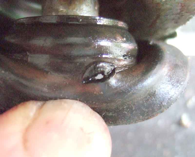
April 2011: Small tear in one of the folds of the diaphragm in the nine year-old valve. What this shows is that with the valve fully closed the diaphragm will still leak coolant from the flow pipe to the heater matrix. But if you remove that hose from the valve and block it off with, say, a spare spark plug and the clip then you should be leak free:
The new (left) and 'nine year' valve showing slight corrosion on the face of the flange ...
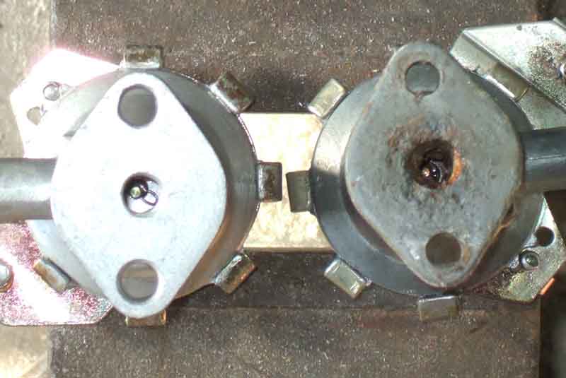
... and also the seat the rubber diaphragm closes onto to fully cut-off flow (arrowed):
Wire spring-clip on the new valve ...
... and circlip on the old:
New valve with the lever fouling the rivet: