Overdrive - LH-Type
LH type without ignition relay LH type with ignition relay - UK LH type with ignition relay - North America Location of gearbox switchLH type without ignition relay (68-76 and V8):
")
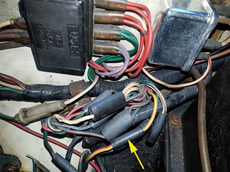
This picture shows the yellow wire from the manual switch coming out of the main harness, joined to a yellow/red going into the gearbox harness, insert the fuse here: (Image by David Farrar on the MGOC Forum)
LH type with ignition relay - UK (77-on):
")
On cars with the gear-lever mounted switch to protect the most wiring a fuse can only be inserted at A where the gearbox harness joins the main harness. A second fuse to protect the rear harness and fuel pump can be inserted at B.
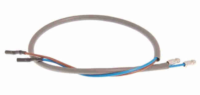 Note: The gear-lever sub-harness has red and black (originally) or brown and blue (currently) wires in a sleeve going to the base of the gear lever. Irrespective of the colours seeming to indicate 'live' and 'neutral' they can be connected to the switch either way round as when operated both wires carry 12v.
LH type with ignition relay - North America (77-on):
")
Note: For a few months from late 76 to Feb 77 the original gearbox Overdrive switch operating in 3rd and 4th was used plus an additional TCSA (Transmission Controlled Spark Advance) microswitch operating in Reverse, 2nd and 4th. Wiring these two switches in series allowed the TCSA i.e. vacuum advance to be enabled in 4th gear only whilst Overdrive was still available in both 3rd and 4th. In Feb 77 (Clausager, although the 1978 model year Repair Operation manual still shows the additional switch), possibly due to unreliability or cost considerations, the microswitch was deleted and the Overdrive switch arrangements changed to operate in 4th gear only, feeding both the TCSA and Overdrive. With this arrangement the output of the gearbox switch fed both the Overdrive manual switch and the TCSA solenoid directly, so OD was only available in 4th gear.
A fuse inserted at 'A' will protect both the OD and the TCSA circuits. There is also position 'B' where a single fuse will protect the OD, TCSA and fuel pump. But a fault in the OD or TCSA wiring will also cut off the fuel pump, so it is probably better to use two fuses - one at 'A' and one at 'C'.
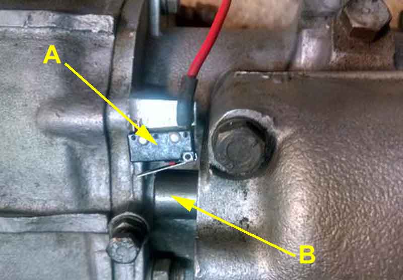
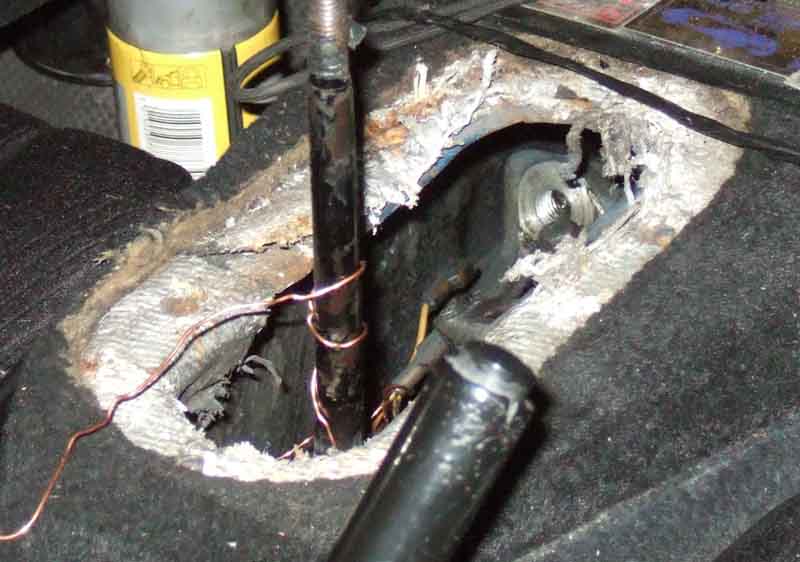
The TCSA micro-switch (A). It will closes in Reverse, 2nd and 4th as the gear change shaft (B) moves forwards in those gears:
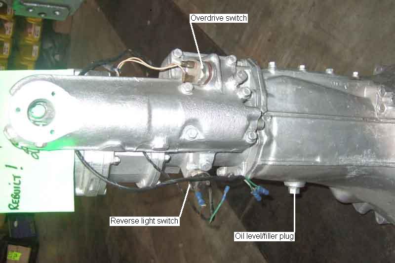
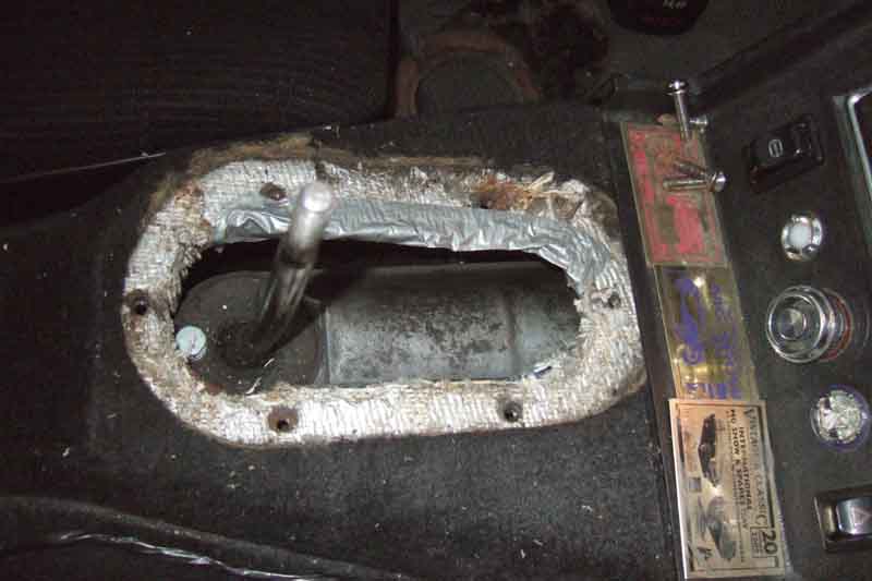
The location of the gearbox Overdrive and reverse light switches. This is a UK rubber bumper 74.5 to 76, but the switches are the same on all four-synch gearboxes:
Showing the large access panel on top of the 3-sync tunnel (left), this should be enough to get at both the OD and reverse light switches: Image from Moss Europe

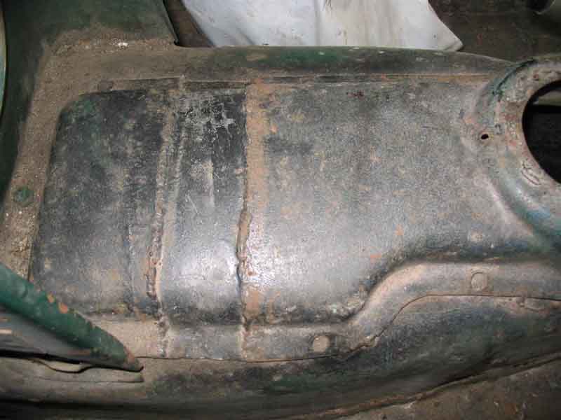
The main reason for this picture was to show how the cover is moved backwards when a 4-synch gearbox is fitted to the earlier car, but you can see the screws in the forward section, and the holes in the rear section which were for the remainder of the screws originally, which has been tack-welded in place, with a filler-strip:
4-synch: Showing the smaller access panel on the 4-sync: Image from Moss Europe
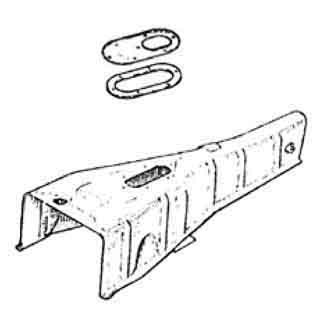
Incidentally this shows the 4-synch removable panel (HZA1431) correctly with the hole for the gearlever towards the rear, it is shown the wrong way round by Moss. Replacement panels do not seem to come with the fibre-board ring that the gaiter screws down onto, instead a full size foam seal AHC188 is shown for under the panel by various suppliers but the Leyland Parts catalogue only shows this under the auto selector unit.
Keep the carpet section from over the panel, and drop it back in place for noise reduction before re-fitting the arm-rest:
Duct-tape over the edges of the hole to protect hands:
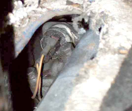
Switch removed, wires tied back to the gear lever to stop them dropping out of sight:
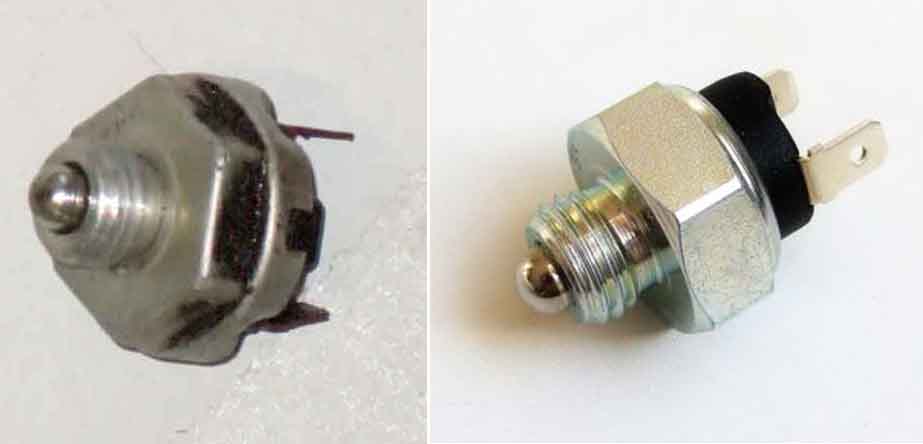
Original switches (left) have the hex smaller than the terminal end, so you can only get an open-ended spanner or grips on them from the side, which isn't possible with the 4-synch OD switch with the gearbox in-situ. However replacement switches (right) have the hex as the widest part, so I'm hoping with Vee's replacement switch (the old one is intermittent) I can get a socket or box spanner on it to make sure it is tight:
... disassembled:
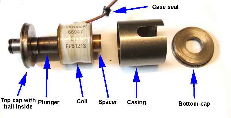
The spacer lifts the coil up, so the plunger is pulled upwards when the coil is energised. Without it the plunger is as likely to be pulled downwards as upwards. However without any of the case fitted, there is almost no magnetic force on the plunger when the coil is energised and it doesn't move at all. With the outer case and bottom cap fitted the plunger moves up slightly as shown. But when the top cap is fitted there is a very strong attraction upwards. You can pull the plunger most of the way out of the bottom, and powering the coil will pull it all the way in and against the top cap with a real smack. It has to resist 400-420 psi of oil pressure in the 4-cylinder OD, and 510-530psi in the V8:
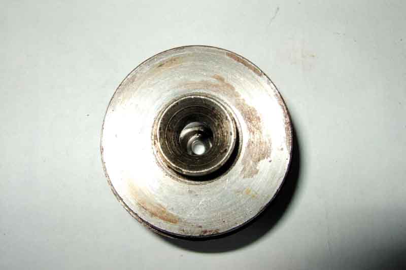
Ball-seat inside top cap:
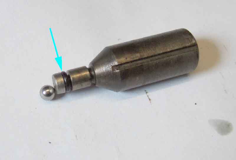
Plunger and ball, small O-ring arrowed, which prevents oil escaping down the inside of the solenoid, and leaking from the cover. The slot in the plunger prevents air-pressure or leaked oil pressure resisting the movement of the plunger. When the plunger presses the ball against its seat oil cannot flow from the inlet to the outlet of the top cap, the pressure rises at the inlet, and OD is engaged:
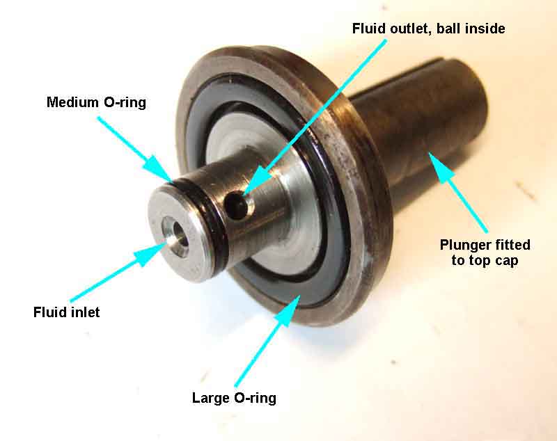
Top cap. When OD is engaged and oil is not flowing from the inlet to the outlet, the medium O-ring prevents oil escaping past the ball when on its seat, which would result in pressure loss. The large O-ring prevents oil escaping down the side of the solenoid, which will leak past the cover:
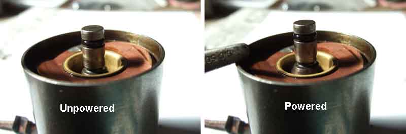
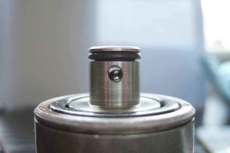
In the released position the ball and plunger should be pushed back so releasing oil pressure. With a sound small O-ring the plunger is unlikely to fall back under its own weight, which is why - apart from possibly the first time the coil is powered after the car has been driven - you won't hear any noise from it, unlike the 3-synch solenoid. If the plunger doesn't move back far enough there may be enough residual pressure to prevent the operating pistons and clutch sliding member moving fully back from the annulus to the outer casing so it can't fully engage direct drive. While the clutch sliding member is between the two there is no engine braking (you still have drive as until OD is fully engaged the one-way clutch is bypassing the slipping clutch) and you get a distinctive 'pulsing' sensation. However under normal circumstances the plunger comes back at least 2mm when the solenoid is released, giving a clear path through the valve, as can be seen here:
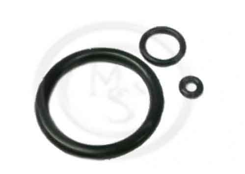
O-ring set (MS&C)
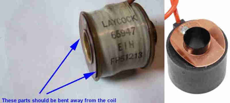
Solenoid coil, with earthing spring. Flat on Bee's removed coil on the left, whereas opposite sides should be bent up to make a good electrical connection when installed in the solenoid body, as with the new one on the right: (Rimmer).