Hydraulic switches Relay Mechanical conversion
Hover over a wire to confirm the colour

Note that late UK cars seem to have a subdivision of the green circuit with its own in-line 35 amp fuse supplied by the white/brown (ignition relay) circuit feeding things like heated rear window, indicators, heater fan and tach, which leaves the original green circuit fuse (2nd one up in the four-way fuse block) feeding things like reverse lights, stop lights, washers, wipers, and circuits associated with the seat belt warning lamp and time delay buzzer.
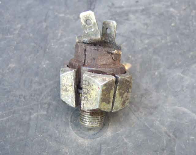
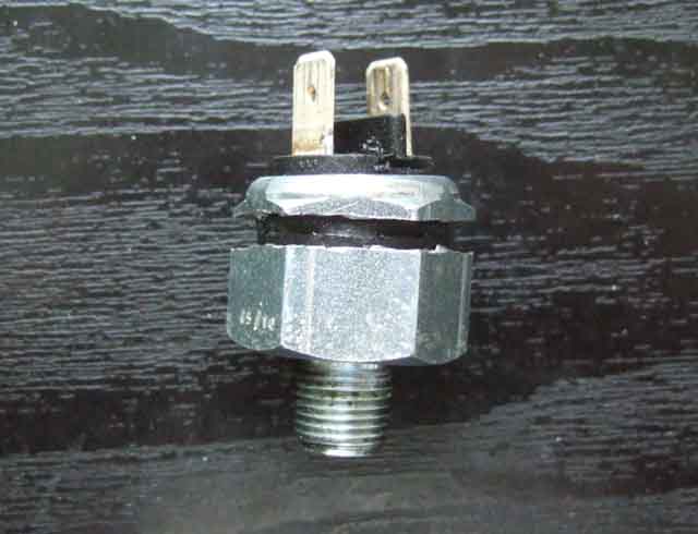
As far as fluid contamination goes although the rubber diaphragm is probably squeezed pretty tightly between the body of the switch and the plastic part forming a seal, maybe silicone can squeeze through that, and maybe modern switches don't compress the diaphragm as tightly anyway, and maybe the contact material is just poorer. But these (a very old switch much before my time 21 years ago, and quite possibly original) look pretty flimsy anyway.
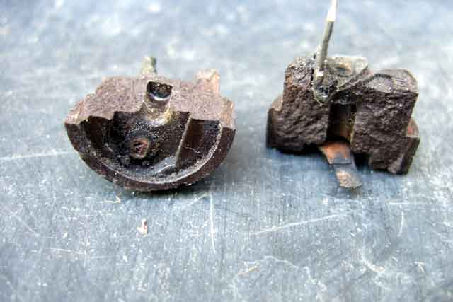
The 'new' switch, showing the position of the cut to open it up:
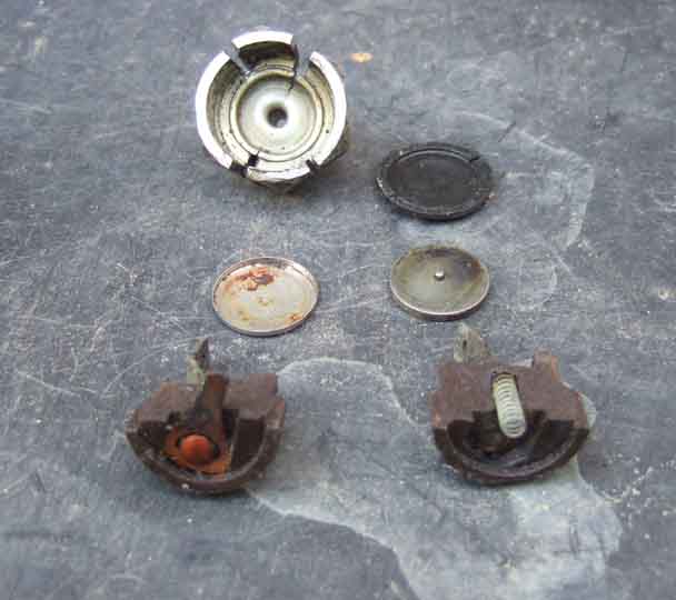
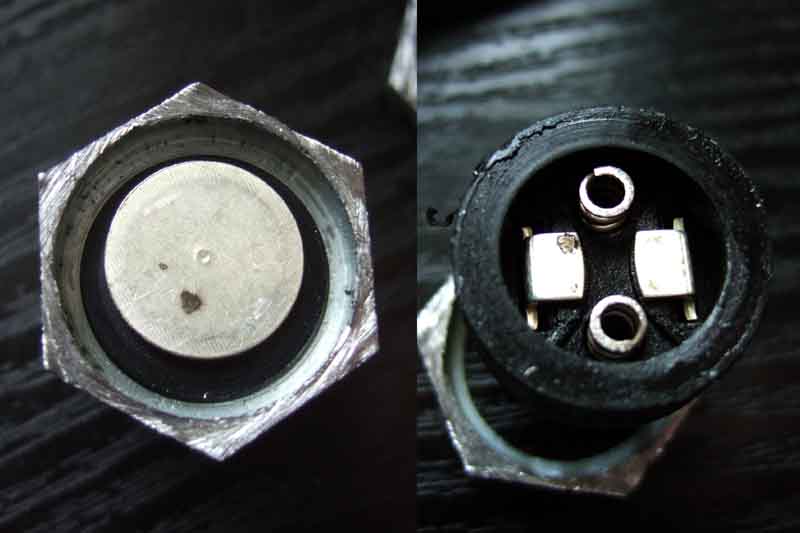
A different internal construction, from left to right: The metal body, the rubber diaphragm, the contact disc (no tin cup), the plastic body containing the two contacts and two springs this time, and the cut-off part of the metal body. The contacts are visibly different, being simply the ends of the pushed-through spades bent over, as compared to the domed-head rivets used to attach the original spades and contacts. Whereas the original design was able to select a different, and more suitable material for the contact surfaces to the spades, the present design does not.
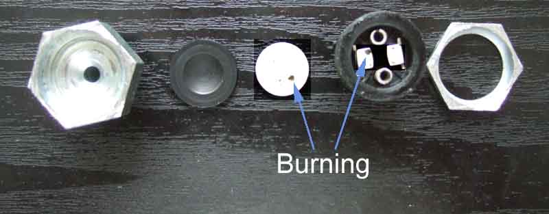
Only slight burning of the disc and contact on this switch compared to the severe burning of the original, but obviously enough to significantly affect operation, almost certainly because there is no rubbing action between the contacts as on the originals.
The LMS switch: (September 2017)
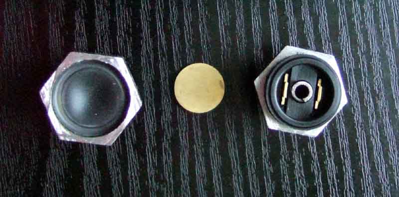
The same basic construction i.e. a disc pressed against the internal part of the spades, but with two possibly significant differences:
- Instead of the ends of the spades being bent over, these are left straight. This could well mean that sharp edges are better able to cut through any burning.
- The material of the spades and discs appears to be different. Instead of possibly soft alloy, these are more brass-like, so could be harder, which may well resist burning better in the first place.
October 2018: LMS now have their switches for sale at about �4 i.e. the same as the usual suspects, so I rather think they are the same poor quality inside.
In an effort to compare hardness I was intending to see how the spades in the two sectioned switches resisted bending. However I couldn't find the one I did four years ago, so decided to use the replacement I got from MGOC which has been in Bee ever since - with a relay ... only to find it has riveted spades!

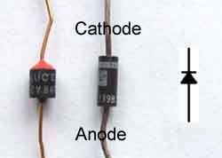 To make one yourself any automotive accessories relay should be suitable. You may be able to get one that includes the diode but this is not usual and you will have to add one. In both cases it is essential to get the diode connected the correct way round or you will blow the green circuit fuse, possibly the diode, and almost certainly your new brake light switch. As shown it is correct for negative earth systems, the older positive earth systems will need to have it wired the other way round. The diode must oppose normal current flow in the circuit as the only time it conducts is in the presence of back EMF from the relay just as the brake light switch contacts open, and that current is in the reverse direction from normal. The diode 'shorts out' the back emf and prevents the brake light switch contacts from sparking and welding just as they open.
Relays with diode protection are available off the shelf, see the 30 Amp Relay With Diode 72714 on this UK site, or the 50 Amp Sealed Automotive Relay With Diode R-50ASD on this North American site. These both have a single diode across the winding which protects against reverse voltage spikes, but there are other types around with a second diode in series with a winding terminal which protects against incorrect connection as well. The types linked above will protect whatever operates the relay, but you must be sure to connect the relay winding the correct way round or you will blow a fuse and/or the diode and/or the switch that is operating it. The series diode in the second type protects against reverse connection as well, if connected the wrong way round the relay simply won't operate. When installing the first type bridge the terminals on the brake light switch or the spade connections on the wiring before pressing the brake pedal (ignition on of course). If the lights operate without blowing the fuse then reconnecting the wiring to the switch and operating the pedal should be fine. If the fuse blows, the relay is wired the wrong way round, and you may have blown the internal diode. You can protect against that by wiring a 12v bulb in series with the relay winding when testing. If the bulb glows at full brightness the wiring is reversed, but won't blow the fuse or damage the relay. If the relay clicks and the brake lights come on, it is connected correctly.
Brake light relays made to order for the MGB as well as other makes and models. They come with a varistor/MOV to protect your switch contacts on both negative and positive earth cars, positive earth cars can subsequently be converted to negative earth without changing the circuit. It uses existing connection points i.e. no cutting of wires, and can be restored to original in moments if required. Just specify your postal address, length of wiring from relay mounting point to switch position, and switch terminal type if they are other than conventional spades. £10 each plus £5.09 (Second Class Signed-for 3 days or less) or £5.99 (First Class Signed-for) to the UK, other countries P&P on request. Payment by PayPal is preferred (selecting Friends and Family would be appreciated), to paulbhunt73@gmail.com, or if you don't have a PayPal account yourself you can click this button and pay with your debit or credit card. Please make sure your postal address is included somewhere as Paypal can vary:
March 2021: If you find your brake pedal needs more and more pressure to light the brake lights then you will need to replace the hydraulic switch at the same time as you fit the relay. If you just fit a relay then the situation may improve, and the switch won't get any worse, but it is already damaged so must be replaced. Mike Robertson has just purchased one saying he replaced his switch about a year ago and it's got progressively worse so the switches obviously haven't got any better! He has another new one to fit with the relay.
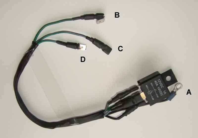
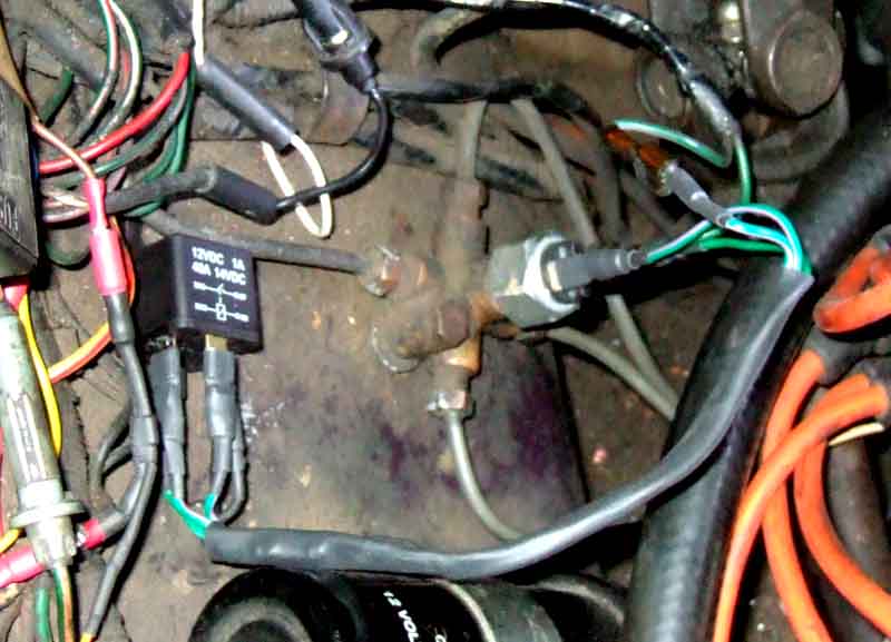
If you mount the relay close to the switch you pick up the earth (A above) from its mounting, and if you use a connector (B) to pick up the green circuit everything can easily be restored to normal very easily if required. But if you connect terminal 30 to the purple circuit at the fusebox instead of the green or via an in-line fuse to the brown, your brake lights will probably be slightly brighter and you will suffer less from the indicators slowing down when the brakes are applied.
January 2020:
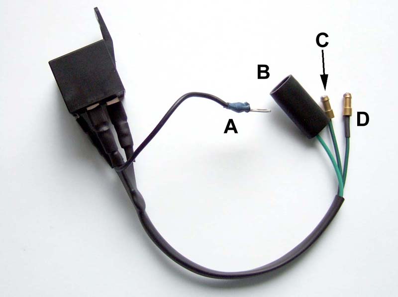 Hank Stallings in North Carolina asked me to make one to work with his mechanical switch, much the same just a bit more care needed in connections as the three wires have identical bullets in place of three different types of spade connector which are self-explanatory.
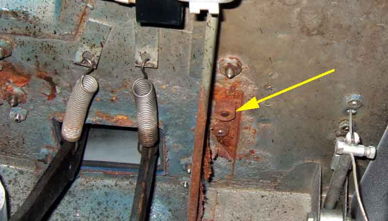
There is a handy stiffener bracket beside the brake pedal giving potential for mounting the switch, but I don't like drilling holes in my cars, and access would be tricky. I can visualise a bracket wrapping round that stiffener, clamping onto it somehow, but that seems a bit fiddly. Looking past that I espy the welded nuts for the bolts that attach the pedal-box to the heater shelf, and one is pretty-well in exactly the right place:
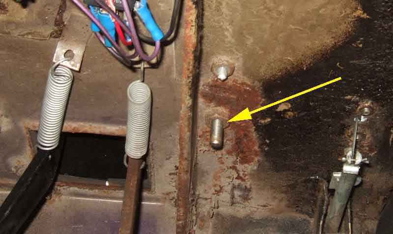
Fitting a longer screw would allow me to attach a bracket using a nut and washers, but while looking at it I realise that the one I'm intending to use is bigger than the other five! Wondering if it is an oddity on the roadster I check the V8 and that is the same. The odd one is 5/16" UNF with a 1/2" head, the others are 1/4" with 7/16" heads. More info on that here:
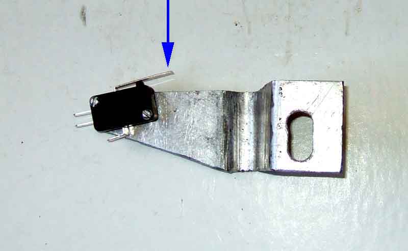
I have some thin strips of steel which are easy to bend into shape and produce a pattern, then use that on some thicker alloy, although quite difficult to get the U-shaped section right. Switch mounted above the bracket out of the way of feet. This type of micro-switch has snap-action contact closure and opening which will resist contact burning far better than the slow opening and closing of the hydraulic switch:
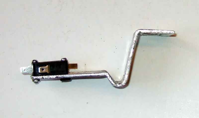
I position the operative corner of the switch off the edge of the bracket, and also past the pedal arm so it is the end of the springy finger that contacts the pedal (arrowed) and not the switch itself, or the bracket. When the brake pedal is released it pushes on the springy finger in the direction of the arrow, which pushes the actuator on the side of the switch in to open the normally-closed contact and turn off the lights. When the brake pedal is operated it moves away from the springy finger, which allows the actuator to pop back out and close the normally closed contact to light the lights. Slot for adjustment purposes:
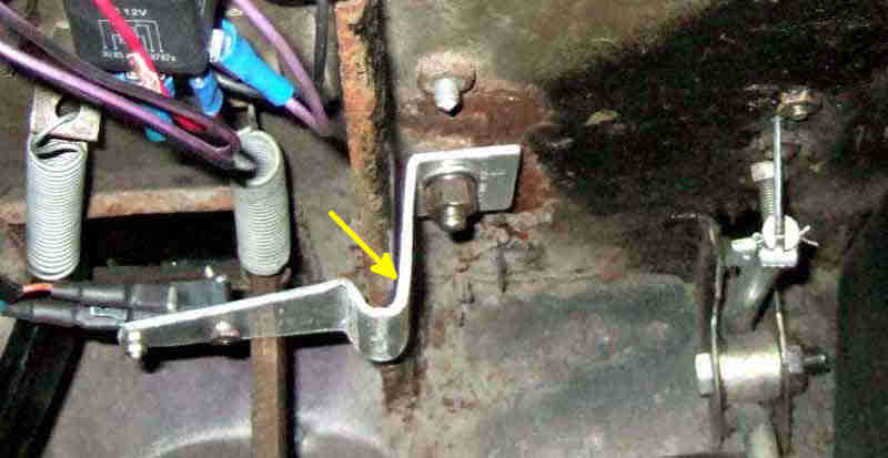
Installed. Initially my thinking was that with the bracket being curled round the flange on the stiffener, it would resist any tendency to pivot away from the pedal which could result in the lights remaining on. Subsequently I realised that a simple 90-degree bend under the stiffener would still be well out of the way of feet in normal use, and by making the bend for the horizontal section that goes on the pedal-box screw a little less than 90 degrees, when tightening the nut the vertical part of the bracket would be pressed hard up against the side of the stiffener (arrowed), having the same effect:
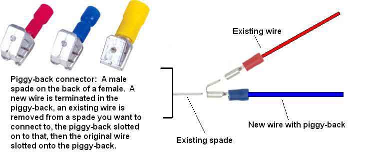
The easiest way to make a connection to the existing wiring is with piggy-back connectors on the ends of the new wires. These push onto the hydraulic switch in place of the existing harness female spades, then those go on the male part of the piggy-backs. This has two benefits - one is that the connections between the new and existing wiring is supported by the hydraulic switch - if you used simple male spades on the ends of the new wires the connection to the existing females would be flapping about and could come loose. The second benefit is that unless your hydraulic switch has already completely failed, it will be acting as a 'second string' to light the brake lights if the mechanical switch should fail. In normal use the mechanical switch will be carrying all the current, there will be no further deterioration of the hydraulic switch electrical contacts, and it will be ready to take over if needed. Periodic checking of the brake lights - as we all should be doing anyway - will soon reveal if the mechanical switch has stopped working as the pedal will need to be pushed further for them to come on:
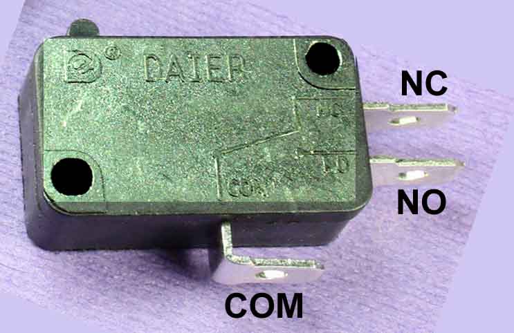
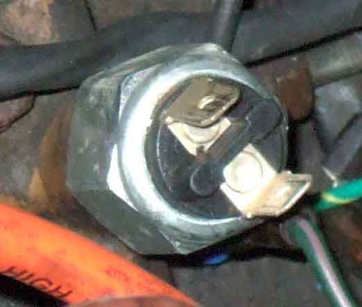
A typical switch (although this one doesn't have the springy finger, there are very many types) showing the connections. You will be using the COM (Common) and NC (Normally Closed) terminals, leaving the NO (Normally Open) unused. It doesn't matter which way round the wires connect to the switch as it is simply joining them together, but if you are interested in convention then the 12v supply would go to COM and the one for the brake lights would go to NC. Update: However Herb Adler has pointed out that wired that way round leaves 12v on the exposed and unused Normally Open terminal when the pedal is not depressed. If you reverse the wires and put 12v on the Normally Closed and the lights on COMmon then that is avoided, a view with which I can concur: