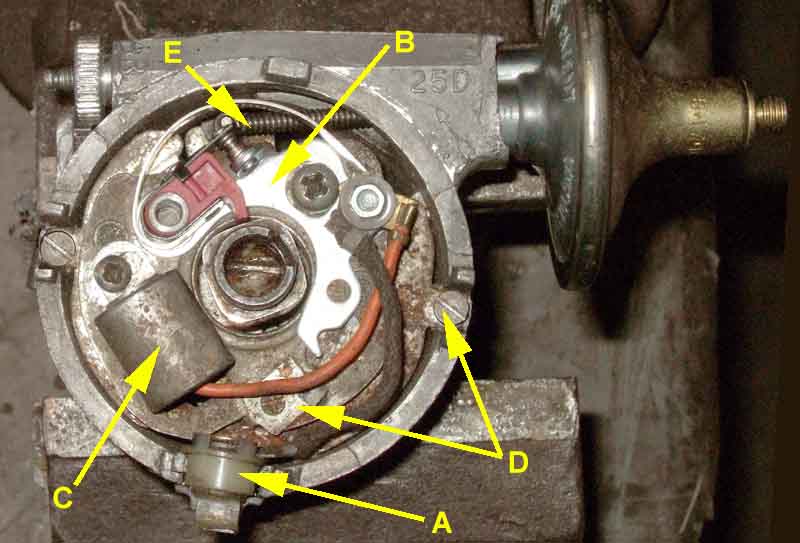
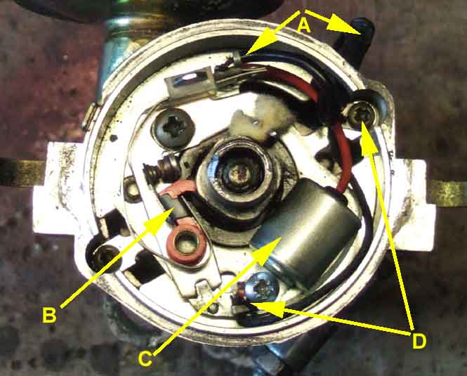
The 25D4 distributor - 'A' the points/coil terminal with a cloth insulated wire to the points terminal stud; 'B' points; 'C' condenser with wire to the points terminal stud; 'D' there should be a cloth-insulated earth wire from a riveted terminal on the points plate to a fixing screw, 'E' the vacuum advance actuator on a pin on the points plate:
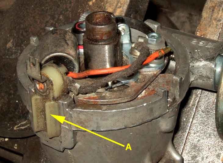
The points/coil terminal:
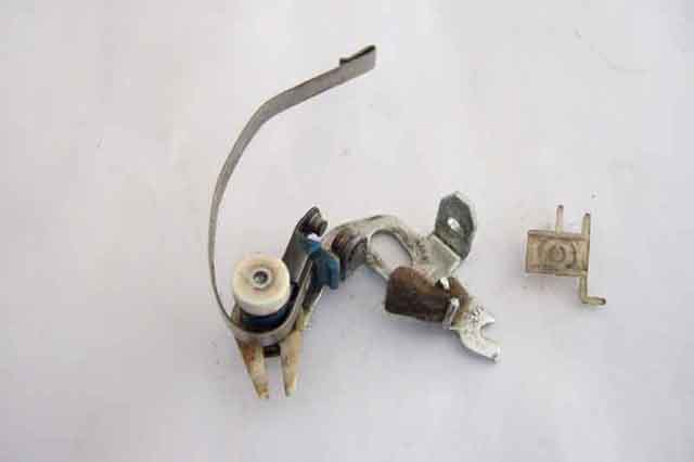
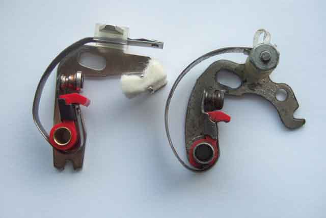
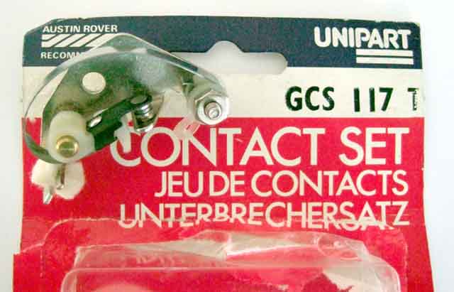
The 'fiddle fit' points for the 25D GCS101 (main image, 2-part GCS107 inset) consisting of several parts which must be assembled in the correct order or you will get ignition problems. Note: These can have white cam-followers from other manufacturers as well as the red from Lucas shown here.
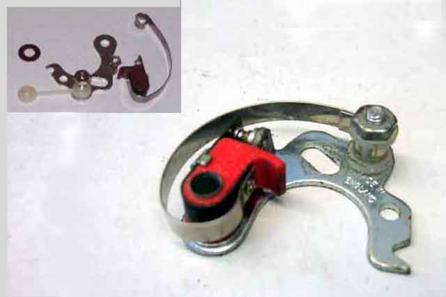
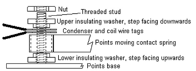
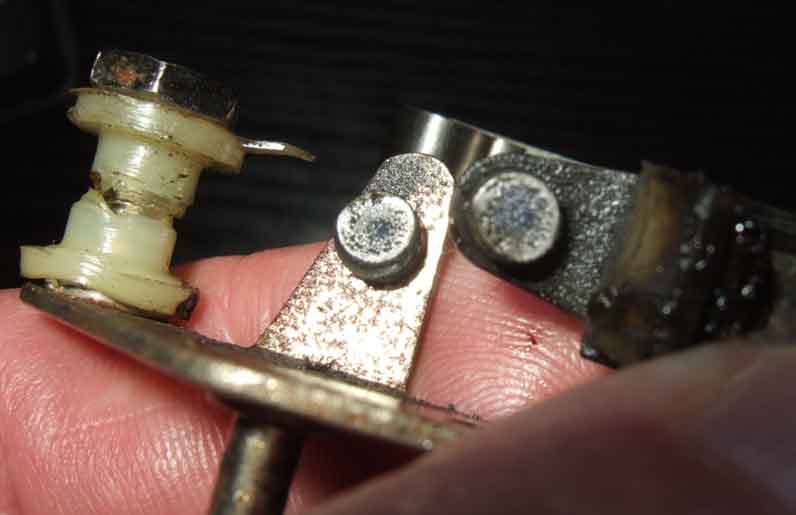
First on the threaded stud is a stepped insulating washer, with the step facing upwards.
Next is the spring of the moving contact, located over the step in the washer.
Next go the condenser and the coil wire tags, in either order.
Next is the other stepped insulating washer, this time with the step facing downwards, so it goes through the holes in the condenser and coil wire tags and the spring of the moving contact.
Finally the nut. These seem to be 'handed' in that one side seems flat and the other side has slightly rounded edges to each flat of the hexagon. I always put the flat side against the upper insulating washer as it just seems more 'correct', but I don't suppose it is critical.
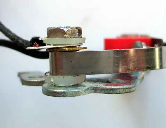
The steps in the insulating washers go inside the holes in the moving contact spring and the condenser and coil wire tags so as to prevent them coming into contact with the threaded stud and nut. These two components are at earth/ground potential, and if the coil wire comes into contact with either stud or nut - either because the washers are the wrong way round, not seated properly, or the tags are between the washer and nut - the points will be bypassed, the coil continually flowing current, and there will be no spark. Also be aware that if the points tag is correct but the condenser tag is fitted between the washer and nut you will have ignition, but very weak sparking and lots of points arcing as the condenser will be out of circuit.
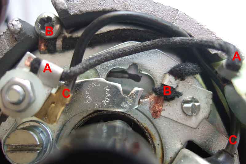
The 45D4 distributor - 'A' points/coil wire entering through a hole in the distributor body; 'B' points; 'C' condenser, the condenser and the points wire have a common connection that slides under a clip on the points spring; 'D' earth wire from condenser screw to points-plate screw:
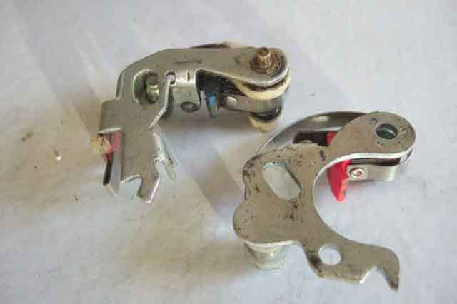
'Quick fit' points for the 45D: 'Fixed' on the left (red cam follower, GCS118) and 'sliding' on the right (blue cam follower, GCS124) with the slotted lever. The felt lubrication pad is used with both types, it rubs on the cam as it rotates and must be greased, not oiled. Note the adjustment notch at the pivot end on the GCS118 and the connection end on the GCS124.
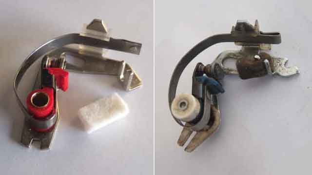
With this type the moving contact spring just lays in a channel in a plastic insulator fixed to a post on the fixed contact base. The end of the spring has a partially flattened loop, and a flat brass connector with the condenser and coil wires already attached simply slides into the loop. The only important thing here is that the plastic insulator does lie between the post and the spring.
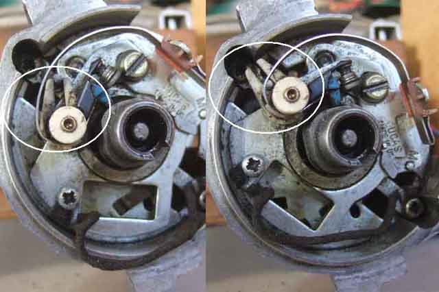
Showing the 45D 'sliding contact' type, with the points plate in the minimum vacuum advance position on the left and the maximum vacuum advance position on the right. Note the difference in angle of the slotted lever (circled):
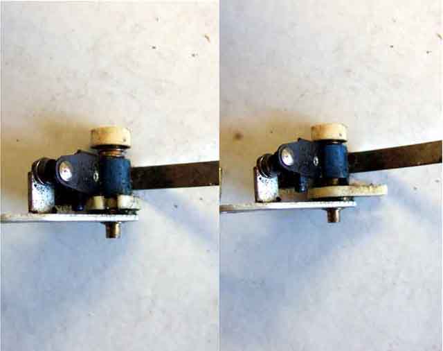
Showing the 45D 'sliding contact' type, with the slotted lever in the minimum advance position (left) and maximum advance position (right). Note the difference in height of the cam follower and the different offset of the points in each case.
The connection arrangements are the same for both fixed and sliding types, however note that they are not interchangeable as the two base-plates are different. The sliding type have a small peg on the points and a locating hole in the base-plate (left), the fixed type have a large location peg on the base plate and a hole in the pivot, similar to the 25D type shown here on the right:
It would appear that the 45D fixed points could be fitted to the 25D points plate and thereby gain the quicker fitting, felt lubrication pad, and do away with one of the braided wires. Whilst the points themselves can be fitted to the points plate it is all downhill from there. You need the 45D condenser assembly as well for the connection tag, which is fair enough, but the mounting tab fouls the adjuster notch on the points, the adjuster notch is at the wrong end making fine adjustment trickier than before, the condenser to connection tab isn't quite long enough, neither is the section of coil wire between the tag and the grommet, and you would have to drill a hole in the spade connection of the 25D to push the coil wire through. These last two can be overcome by cutting the wire short and soldering it to the 25D spade (possibly compromising reliability), and trimming the condenser mounting tab, but that still leaves the condenser wire too short and it probably isn't worth the faffing about.
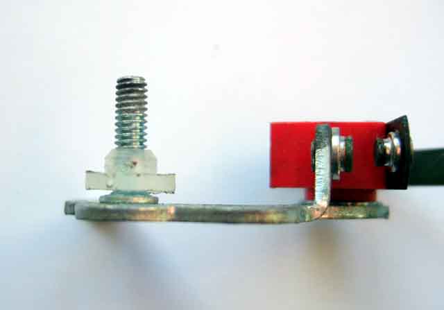
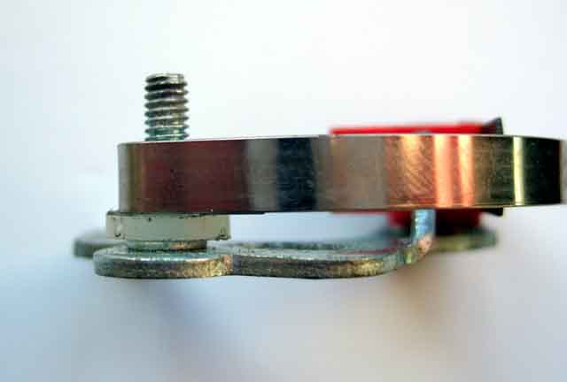
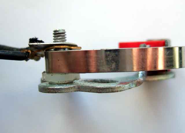
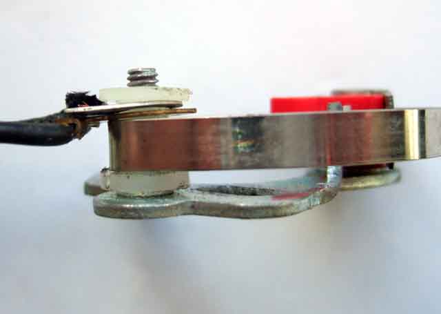
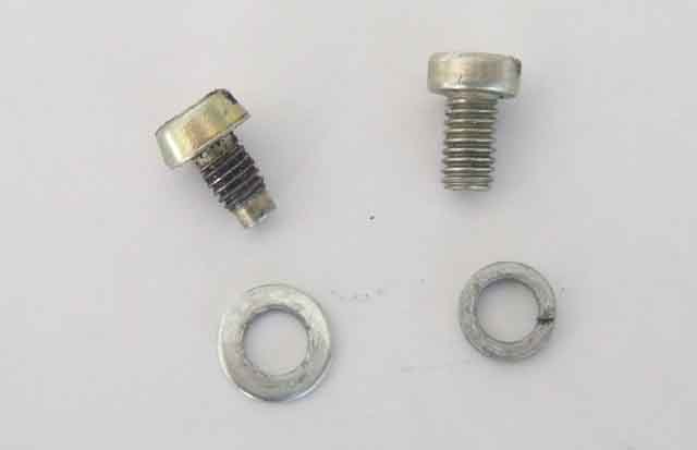
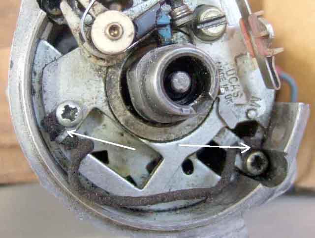
All types of points are secured with a screw, spring washer and plain washer. On an original distributor in my possession the screw is unusual in that it has a plain, narrower portion at the tip before the thread starts (shown on the left below). This aids insertion as you can drop it and the washers into the hole in the points, the plain tip drops into the threaded hole in the points plate, holding the screw upright and relatively secure while you get the screwdriver on it and start to tighten it. Replacement screws, and those in rebuilt distributors, seem to be standard screws threaded for their full length (on the right). With these you really have to drop the screw and washer onto the top of the points while they are out of the distributor, then move the points towards the points plate with one hand and a screwdriver in the other pressing gently down on the screw head. Before the points are lowered all the way to lie on the points plate start turning the screwdriver to start the screw, and then you can let the points go. If you let the points lie on the points plate before the screw has started it will topple over and there is a good chance the washers at least will fall into the centrifugal mechanism. Not too bad if the distributor is already removed as you can just up-end it, shake it, and hope to catch the bits as they fall out, but a nuisance if the distributor is still installed.
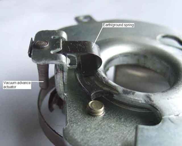
Both 25D and 45D have earth/ground springs between the moving points plate and the fixed base plate, which should mean that a separate earth/ground wire is not required. But having experienced intermittent cutting out when pressing the throttle on a Scimitar GTE - usually just when pulling out into traffic(!), with a Ford distributor that only had the sliding contact by design, I wouldn't recommend it. In fact the first Scimitar tip I came across was to retro-fit a ground wire, which I did, and it solved the problem. This is the 25D ...
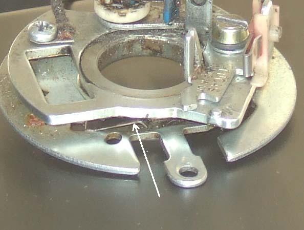
... and this the 45D:
25D4 internal wires - 'A' is the coil to points wire from the spade terminal on the side; 'B' is the earth wire from the moving points plate (spot-welded and riveted) to the distributor body (screwed); and 'C' is the condenser wire from the points connection:
45D cloth-insulated earth/ground wire fitted, under the condenser fixing screw (condenser removed for clarity) and points plate fixing screw, This can be used on a 25D4 with a bit of ingenuity:
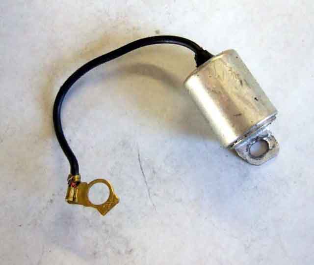
The condenser for the 25D distributor, that for the 35D8 for the V8 is very similar:
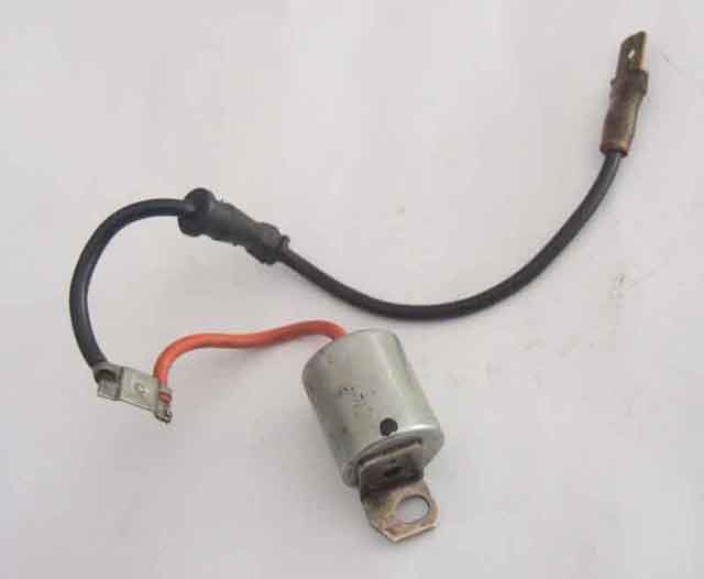
Combined condenser, coil wire and points connection tag for the 45D distributor:
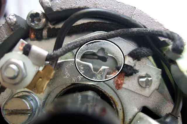
Fine adjustment V-notches of the 25D (circled). With the points screw only lightly tightened a screwdriver inserted in the notches can be twisted one way and the other to open or close the gap. Because the fixing screw is only lightly tightened, when the screwdriver is removed the gap remains the same, the screw can then be fully tightened, and the gap rechecked to make sure it hasn't shifted.
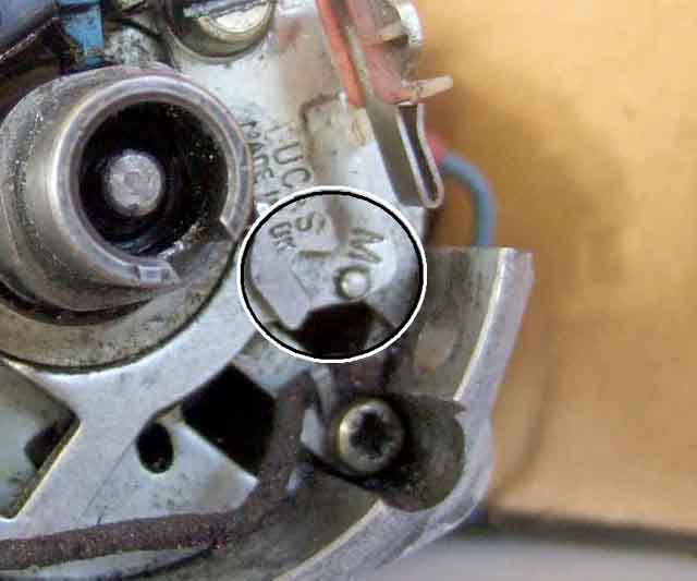
The fine adjustment 'V-notch and pip' (circled) of 45D sliding points (45D fixed points have the V-notch at the pivot end of the points plate):
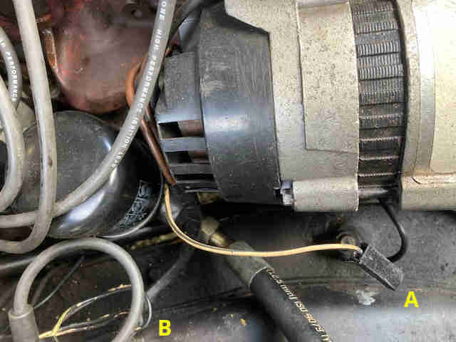
Originally the distributor wire came out of the harness with the coil wires ('B' below) but at some time it was changed to come out with the alternator wires ('A') and be routed behind the coil, possibly to avoid getting wrapped round the steering column. This on a late model (the wire is unused as it had been converted to electronic ignition):
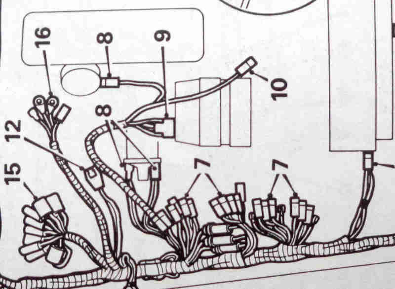
Confirmed in the 1978 Leyland Workshop Manual which shows the distributor wire (upper item '8') coming out with the alternator ('9') and temp sensor ('10') wires and not the coil wires (lower item '8'):
The V8 35D8 points. These are one-part 'fiddle-fit', but with the felt rubbing pad of the quick-fit 45D types. This is fitted at the pivot end of the points rather than the contacts end, which may be because the distributor rotates in the other direction to the 4-cylinder types i.e. clockwise instead of anti-clockwise. They have the peg to locate in the hole in the points plate like the 45D sliding type, but are non-sliding! They don't have the fine adjustment notches of the 4-cylinder types as the 35D8 distributor has an external hex bar with which to adjust the gap/dwell (see below).
August 2021: I suspect I fitted the above set in March 2008 (as I had obviously taken them out of the packet) and that was 30k miles ago! As usual I would have bought a new spare set and carried them around with me ever since, only took them out of the packet to fit them to discover no felt pad unlike the above, so had to change that over. The contact points on the (probably) 30k set are in remarkably good condition:
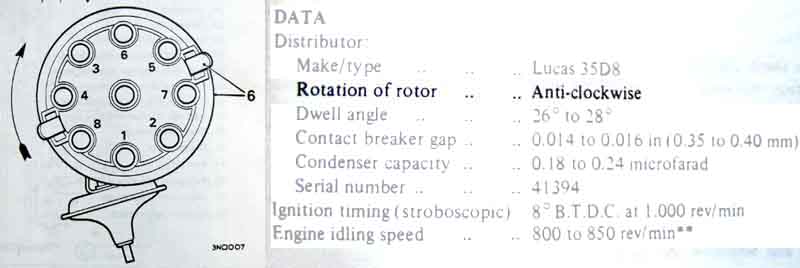
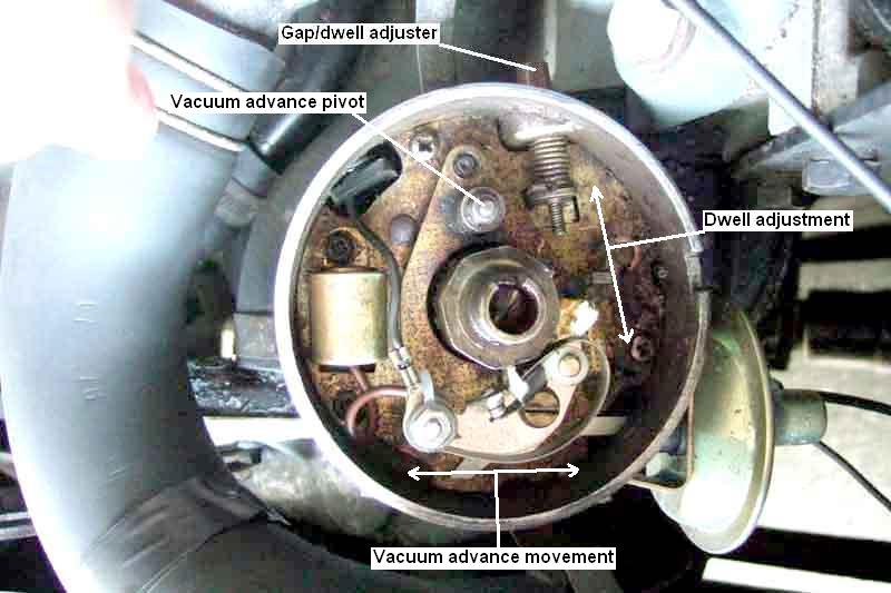
The V8 35D8 distributor. This has an external hex bar to set the points gap/dwell and means it can be set with the distributor cap on and the engine running. The hex bar moves the points plate up and down (in this image) i.e. moves the points closer to or further away from the cam to decrease/increase respectively the gap/dwell, whereas the vacuum advance capsule pivots the plate about a point at the top of the points plate, so moving the points back and fore across the face of the cam to alter the timing. When making adjustments to dwell screwing the hex bar 'in' continuously pulls the points plate 'up' to decrease the dwell, but when unscrewing to increase dwell it relies on the spring over the screw to push the points plate away (down). Because of stiction it means that the points will move in a series of jumps in that direction, even if you push or waggle the hex bar after each movement. For that reason you will need to 'unscrew' the hex bar until the dwell jumps above the required value, then carefully screw it back in bit by bit to gradually decrease the dwell to the required value. If you go too far you will have to repeat the process. Note that the orientation of the points is the same as for 4-cylinder distributors despite rotating in the opposite direction:
January 2021: Note also that the drawing correctly shows the direction of rotation as clockwise, but the Data incorrectly states it as anti-clockwise. Jonathan Moulds pointed this out, I looked at the drawing 25 years ago but obviously never read and more importantly absorbed the text: