Chrome Bumper
Rubber Bumper
Hardi pumps
Vents
Cut-off
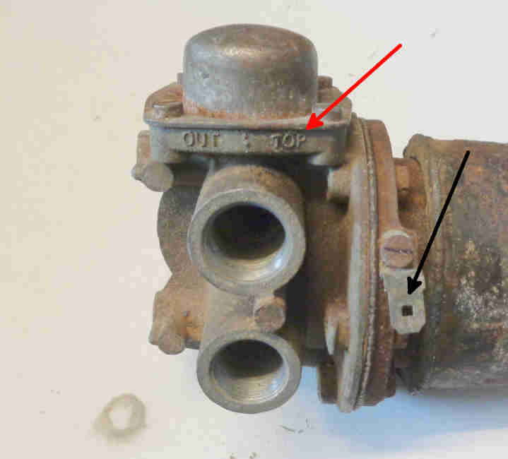
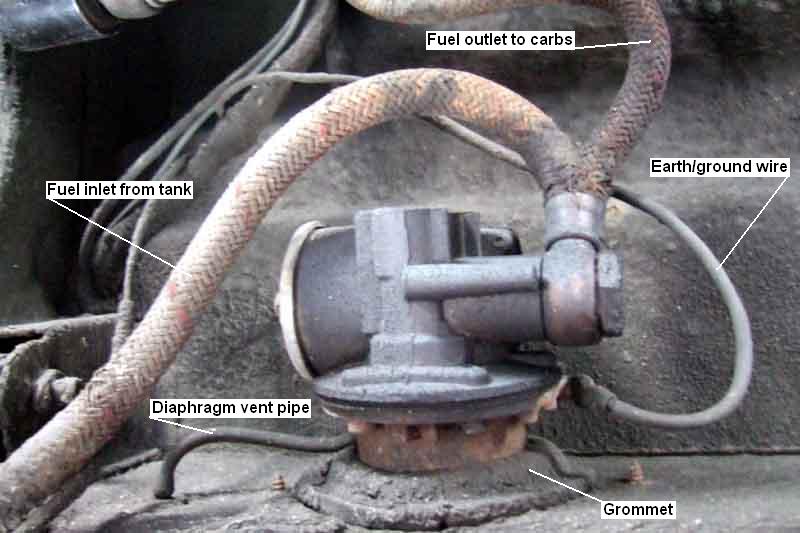
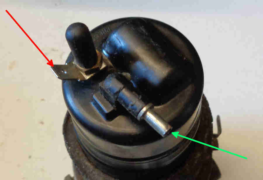
Note the orientation - the two tapped but unused holes facing the viewer are vertical, and the pump ports face forwards. There is a 'TOP' marking on the body of the pump (red arrow) but facing forwards so not visible when mounted. Also indicated is the earth connection to the pump (black arrow):
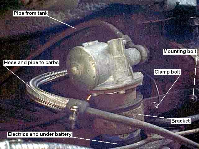
But getting at everything is another matter, the electrics end particularly, which is concealed within the frame-work for the right-hand battery. The bracket mounting stud shown is the lower one, there is another above the pump and slightly rearward of this one. There is a rubber sleeve AHH6708 (available June 2020) round the pump body under the bracket (AHH6709):
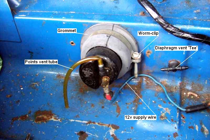
A large worm-clip is fitted around the grommet clamping onto the pump body, which together with the panel edge in the groove of the grommet seals against water entry. The 12v supply wire is connected to the pump terminal. A short length of plastic tubing connects to the vent port on the end-cap and hangs downwards (prevents any debris or water dropping into the upward-pointing port). I can't remember where this came from - Vee came to me with a Moprod pump that doesn't have vents and hence no tubing, this pump is the refurbed one from Bee, and Bee's vent tubes went onto the replacement pump:
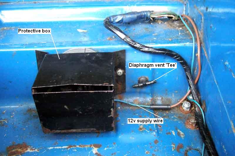
A metal box screws to the boot front wall to protect the pump and wiring from damage from heavy objects in the boot. The arms of the vent 'Tee' are left unconnected and pointing horizontally. Note the new brown wire added by a PO when the pump obviously shorted and burnt out the original white wire in the rear harness, the vestiges can be seen where the harness enters the boot. Fortunately the rest of the wires in the harness weren't damaged enough to warrant replacement of the complete harness, nor the main harness which also suffered some damage. See 'Pump Fusing' on the main page to protect against the possibility of this on your car:
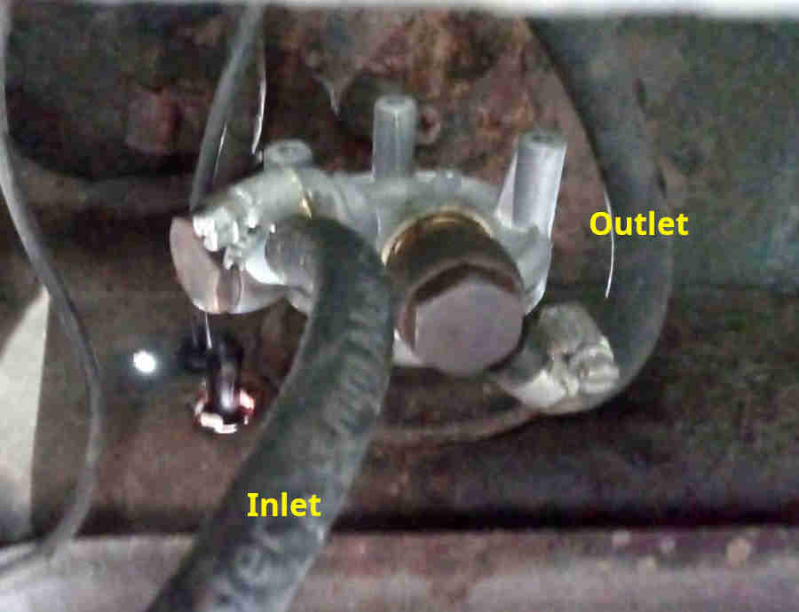
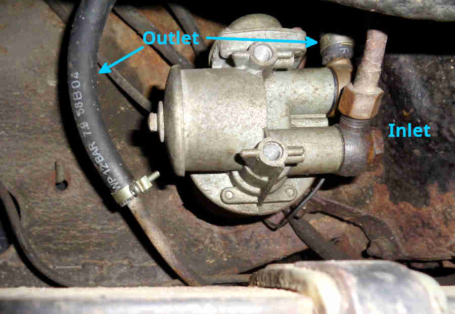
Rotated so that the outlet is above the inlet and angled upwards, but still clearing the underside of the bulkhead shelf. The banjo bolts had to be slackened to achieve this:

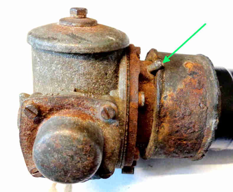
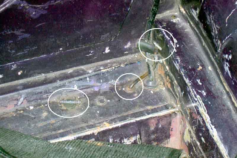
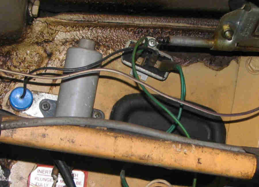
The electrics-end vent (green arrow), also showing the 12v connection (red arrow):
64 roadster - it's not clear whether there is a vent coming into the boot through the same hole as the harness, or terminates elsewhere: (Clausager)
69 roadster - one vent coming up beside the harness and the other further inboard: (Clausager)
71 roadster - one with the harness above the chassis rail and the other one sticking up jauntily from the 'shelf': (Clausager)
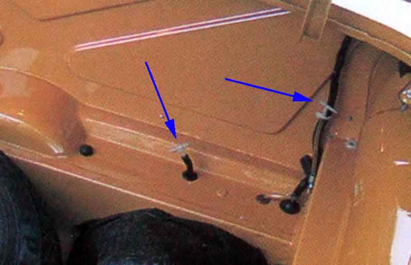
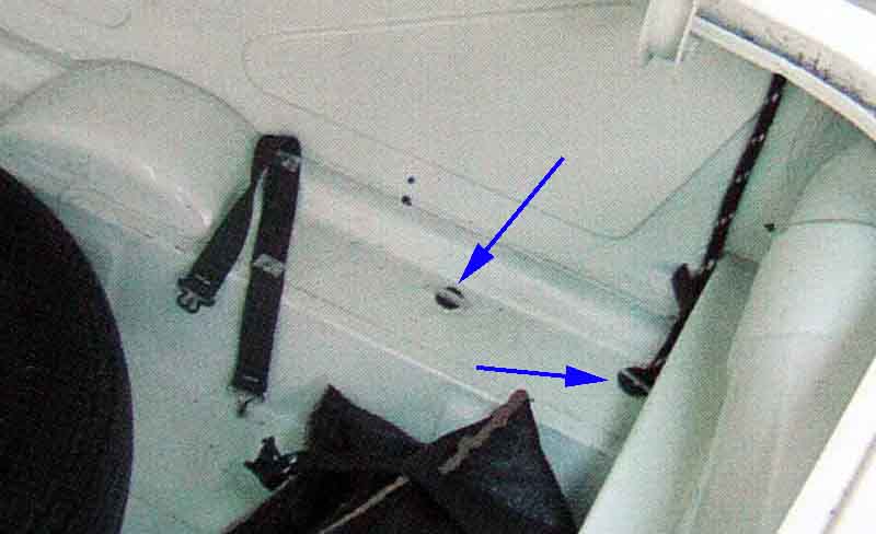
The vent pipes in the boot of my 73 roadster. For some reason one terminates on the shelf and the other is brought up beside the chassis rail. Clausager's 69 and 71 are the same. The pipe and tee on the right are narrower bore than the ones on the left:
My 75 V8, Clausager appears to show the tube being run up to the harness and clipped there on page 29:
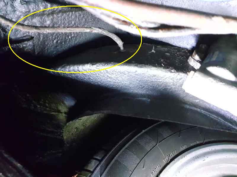
Steve Livesley's 75 roadster has the tube going to a nipple on the side of the chassis rail just in front of the damper:
80 roadster - a grommet where one of them used to be. What could be the earth wire or more likely a suppression capacitor: (Clausager)
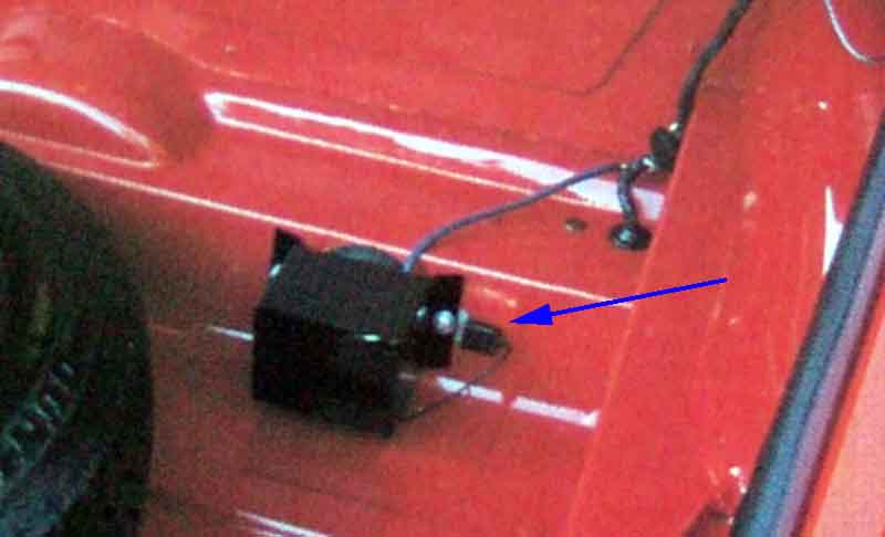
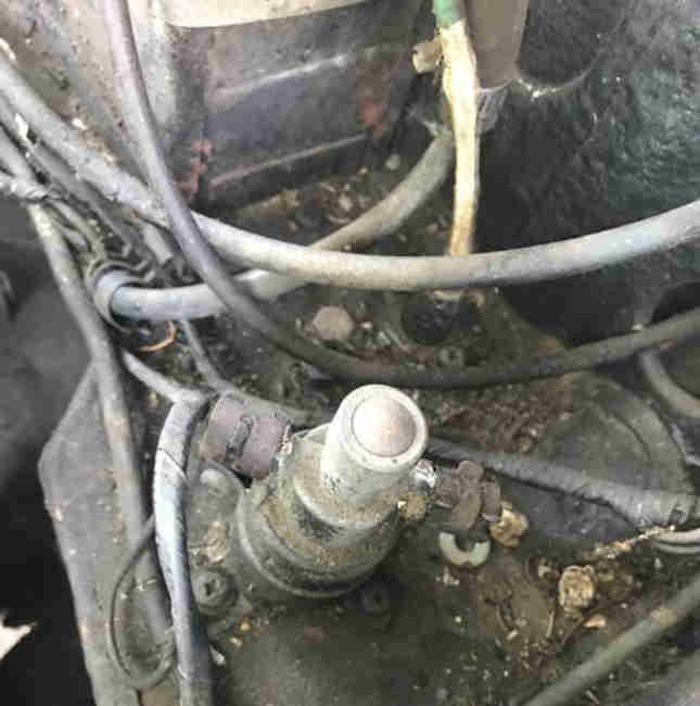
A second fuel shut-off device on North American cars that came into play in the event of a roll-over, this one physically cutting off the fuel flow. However John Twist says they invariably leak and strongly advises bypassing it, as this one has been: (MG Experience)