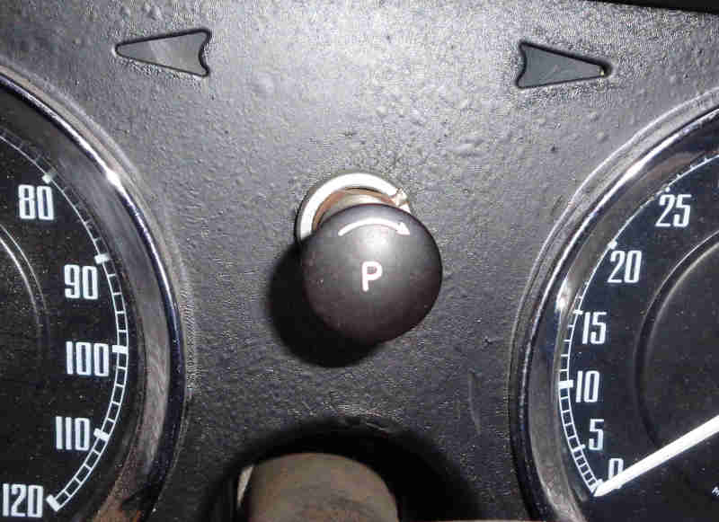
Originally the rheostat knob showed a 'P' symbol - AHH5368:
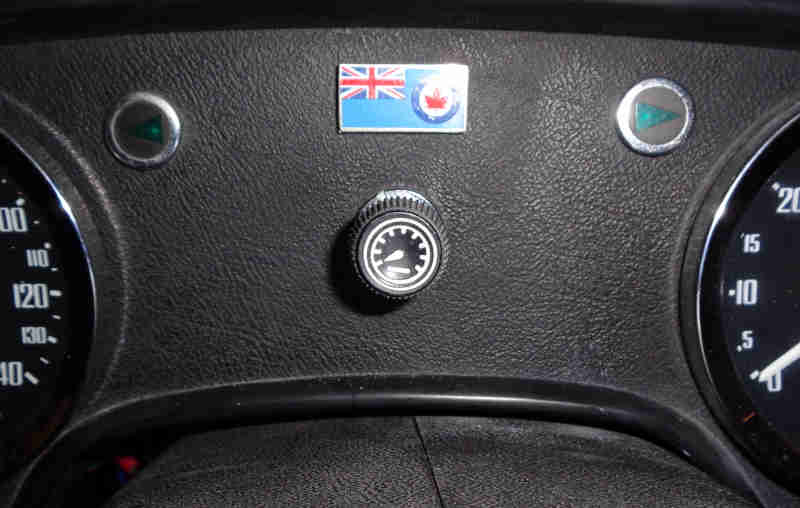
Changing to a representation of a speedometer on North American Mk2 cars and V8s, and late CB/RB cars for other markets - 37H7995:
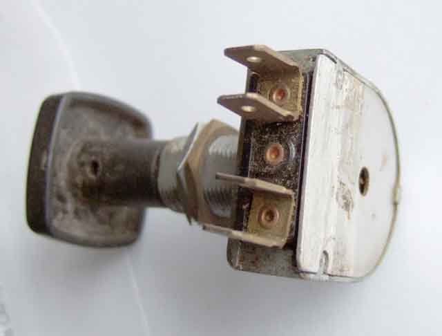
Showing the recessed push-button in the rheostat knob (this square one is not from an MGB), and also the two nuts on the threaded portion of the rheostat body. The brass nut is there for aesthetic reasons to space the rheostat back from the panel so that the outer nut ends up flush with the end of the threaded section, and doesn't leave exposed threads:
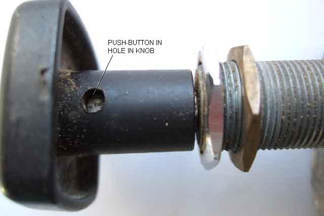
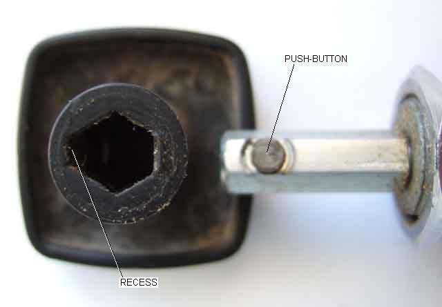
Showing the push-button in the shaft, and the recessed face of the hexagon in the knob which must go over the push-button when refitting:
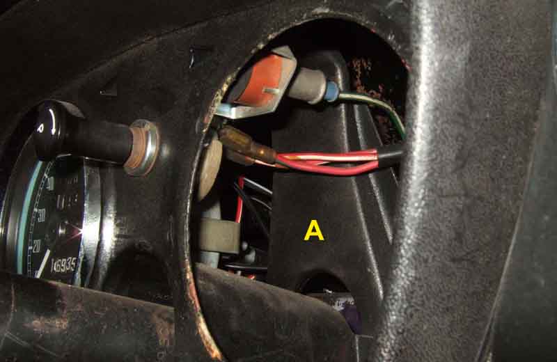
The CB (except V8) bracing panel 'A' behind the rheostat and between the two main dials which prevents access to the back of the rheostat directly. The column switch cowl may also need to be removed to be able to withdraw the tach depending on the vertical positioning of the column. You may be able to reach the connections like this, but having got this far two more steps to remove the knob and rheostat locking ring and you should be able to get it out through the tach hole:
V8 and RB without the bracing panel, which together with the smaller main dials gives better access:

Just by removing the knob, locking ring and wavy washer you should be able to withdraw it from the dash and bring it down far enough to access the connections:
General view of a printed-circuit rheostat (from a previous car) showing the two spades for each terminal in a 'U' shape:
Internal view of the rheostat showing multiple printed circuit tracks of varying thickness and length, and heat damage at the bottom 'X' near the point of maximum current and brightness. The lowest wiper 'A' is feeding input current to the inner ring of track. The upper wiper 'B' - shown near the minimum brightness position - runs across a series of pads with tracks that loop to the adjacent pads. Each loop has a different length and resistance of track, the upper pads with long, thin tracks of relatively high resistance, getting shorter and thicker as you go round in an anti-clockwise direction, to end at the wider pad bottom right. When the upper wiper is on that wider pad the lamps are at maximum brightness:
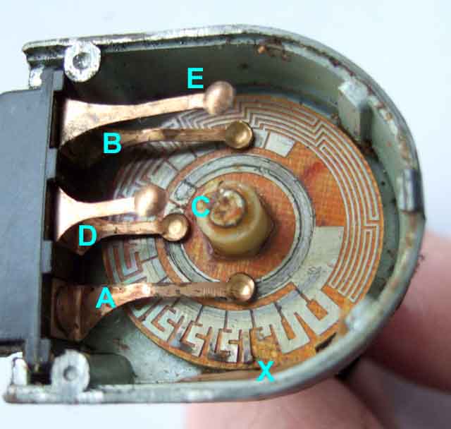
Note that the ring, at top left just above the middle wiper, has two breaks leaving a pad 'C'. When the lower wiper is on this pad the lamps are extinguished. This is at the 'brightest' end on this rheostat, although some extinguish at the dim end. The short wipers in the middle 'D' act as a bridge between this section of PCB and the upper section which is on the back of the cover. This wiper feeds input current to that section of track, and the upper section of the top wiper 'E' feeds it to the output terminal. The direction of current flow is not important, I just use 'input' and 'output' for clarity.
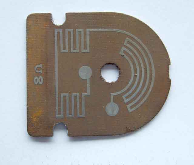
View of the rheostat back plate showing another track and the inscription '8 ohms' which refers to the resistance of that section of track. This is a fixed resistance, and is in parallel with the variable section, taking some of the current to reduce the heat and risk of damage to the variable part. The effect is that the rheostat varies between 0 ohms and 8 ohms. When the variable section suffers heat damage it's usually at the brighter end, where the current is at its highest over a short length of track, so the heat develop developed is highest. The effect of a break here is usually that the rheostat does vary brightness, but at it's brightest it is not as bright as it should be. This means it's not obvious that it is faulty, unless you bypass it:
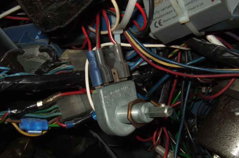
All mine (two other cars as well as two MGBs all failed ) have been the above printed-circuit type but most people say theirs are wire-wound as here which have a completely different appearance. Less susceptible to burning out, may suffer from a poor connection between the wiper and the winding, but can be cleaned. The base on these is insulated either white ceramic as here or blue plastic, with visible windings through the ventilation slots, and the spade pairs are rotated through 90 degrees. This type are usually stiffer to rotate, and have a 'scratchy' sound and feel compared to the printed-circuit type:

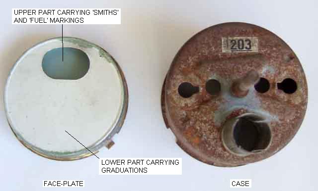
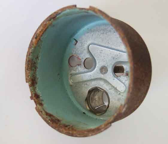
Inside of a fuel gauge case showing the 'duck-egg blue' paint, which tends to make the yellow light from a low-wattage incandescent bulb whiter:
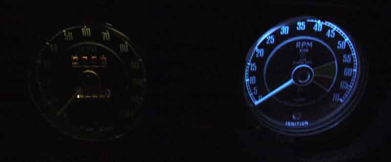
Using bright white LEDs can result in a bluish tinge to the light, which I don't find unpleasant. More info on LEDs here:
Showing the back of the fuel gauge face-plate relative to the case
which has the same blue colour on the back of the upper part (carrying the 'SMITHS' and 'FUEL' markings) but matt white on the back of the main part, the lower half of which carries the graduations. The bulb is situated at the bottom of the case and so mainly illuminates the white area of the face plate and the inside of the case. Light scatter then has to occur to get through the aperture at the top of the face-plate, which then has to scatter still further before it reaches the pointer and graduations: