
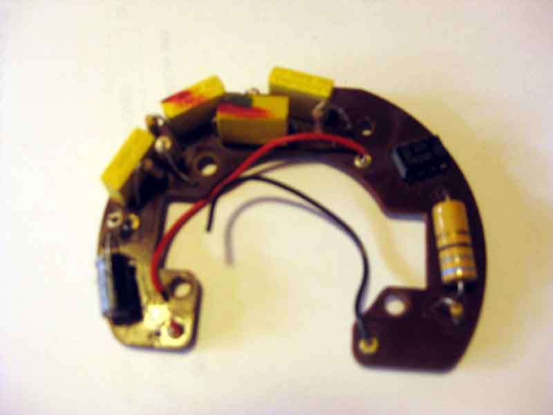
The following circuit diagram was derived by Herb Adler while he had his 2415 open on the bench, also a picture of his circuit board which is very similar to the RVI board in general appearance.
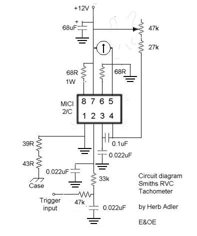
The functioning is almost the same as with the RVI type, that is an incoming ignition pulse triggers a fixed-width pulse to the meter, and the faster the pulses come in the more pulses are sent to the meter each second. The effect of this is that the periods where the meter is NOT energised get shorter and shorter with increasing RPM. The meter cannot respond fast enough to indicate each on period and each off period, but instead displays an average voltage based on the length of the 'off' periods relative to the 'on' periods of the pulses it is receiving. So, as the RPM goes up, the meter indication goes up.
Franz Hubl has a 2415/00AF tach which didn't work, and on opening it up he found a non-standard circuit board inside which wasn't fully connected and had a capacitor lying loose in the case, and asked if I could help.
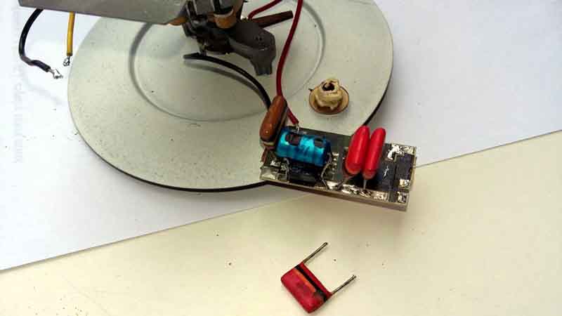
That circuit board was unknown to me, but from further research Franz found reference to it via Rick Astley's MGB Electrical Systems, page 154, where he refers to this document. Rick covers the original curved circuit board in some detail, but also shows the smaller rectangular board that Franz has, which was used in 1410 tachs for other markets and had been used to replace Franz's original by a PO ... who then apparently gave up on the job.
Franz also found a replacement IC to the original (and NLA) TI MIC 2/C, which is the SAK215 available from many sources such as DatasheetCatalog.com, which may be a better bet in the event of a faulty IC rather than constructing the completely different circuit based on a 555 timer that Rick also covers.