Gauges Schematic
Early system Late system
Hover over a wire to confirm the colour
Early system - internally stabilised:
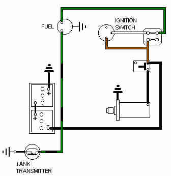
Note: The gauge earth is required for its correct functioning as well as for its illumination, and the green and green/black wires may need to be connected the right way round to function correctly.
Late system - external stabiliser module:
These gauges can be connected either way round. Oil and temp gauges only applicable where electric units are fitted in place of capillary units.

Notes:
- For the first year of the North American padded dash and electric oil and temp gauges (Mk2, 1967) instead of a light-green/green wire coming from the instrument voltage stabiliser to the first gauge (fuel) it is shown as a green wire. This wire then daisy-chains to the oil gauge as a light-green/green, then daisy-chains from there to the temp gauge as a green again. After this first year the schematics are as above i.e. only the fuel and electric temp gauges are fed from the stabiliser, the oil gauge is fed direct. Apart from the different wire colour the oil gauge being fed from the stabiliser could have been required if a non-stabilising sender had been used for just that year, but the Parts Catalogue doesn't show that. Certainly the later sender was an industry-standard device which included its own stabilisation function as well as pressure transducer. Therefore it either was connected to the stabiliser, erroneously, or it is an error on the schematic. With two separate stabilisation circuits in series I would expect the oil gauge to read low, meaning that perhaps it is just a schematic error.
- North America reverted to a capillary oil gauge in 1972 for the remainder of production.
- UK always had a capillary oil gauge, and the temp gauge only became electric in 1977.
- The schematics show this as white/brown as indicated, which is the same colour as from the starter relay to the starter solenoid on 1971 models. However that wire will be a heavy gauge and the oil gauge wire standard gauge.
- Prior to the latter part of the 72 model year all the factory schematics show the sender as using a wired earth back to a number-plate bolt on the rear panel. At that point North American schematics imply this changed to an earth picked up from its attachment to the tank, but RHD schematics show the wired earth carrying on until the 1977 model year when the sender changed to one incorporating the fuel pick-up. However my UK 73 has a wired earth in the harness tail, but my 75 V8 does not and neither does an North American 1976. The routing of the sender tail also changed at some point between 73 and 75, possibly both changed with rubber bumpers.
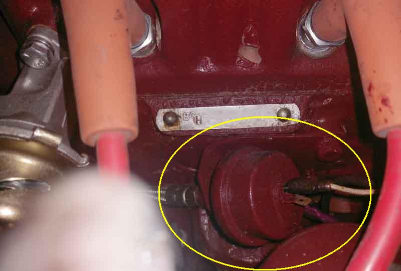
The electric oil gauge sender (circled) with (braided in this case) hose from the usual place and white/brown wire, attached to the now-unused rear dynamo mounting point with a bracket: (Bill Etter)