
by Herb Adler 5243 3409
More in the saga of mods / improvements.
I was having issues with the fuel gauge, making no sense what ever.
Trouble shooting started with testing the voltage regulator, which had indefinite readings, I know it's a switching regulator and its output is either full 12V or 0V and on a meter it would fluctuate around some median value. Well mine fluctuated all right, all over the place. So rather than try to find another I decided to go modern and convert it to an electronic one.
First remove it from the car, by unscrewing the single bolt holding it to the firewall behind the dash on the driver's side, RHD cars. Once you have it on the bench carefully open the metal can. I used a pair of end cutters, like side cutters but the cutting edges are at 90 deg to the handles. Remove the fibre board, which has the works riveted to it, see Figure 1.
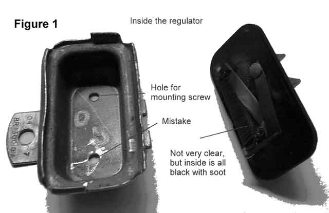
Remove, by cutting, all the works, leaving only the rivets and spade lugs. Wires will be soldered to these later.
Drill a 1/8” hole in the metal case, next to the mounting lug, but far enough away to give clearance room for the mounting screw head. I messed up with my first try and got it too close, so that the head overlapped the lug and hence stood out too proud. Deburr this hole, otherwise you will wind up with a short, lots of heat and melting wires; remember the B is not well fused (This circuit is fused. Ed.). See Figure 1.
Now you will need to acquire the parts, from an electronics outlet, such as Jaycar or Dick Smith. You will need these components, plus solder, wire, thermal conducting paste and shrink or plastic sleeving.
1 off LM317 three terminal voltage regulator, plastic style.
1 off insulating kit to suit the LM 317, washer and bush
1 off 220 ohm Ľ watt resistor
1 off 1k5 (1500) ohm Ľ watt resistor
1 off 10 uF 25V electrolytic capacitor.
1 off soldering lug
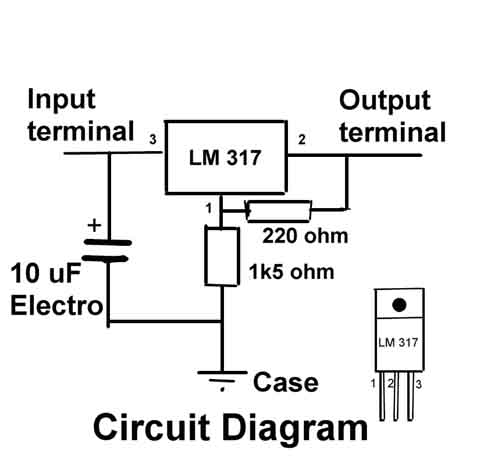
These will make a standard fixed voltage regulator, as shown in the Circuit Diagram.
Study the Assembly Drawing, noting particularly where the insulating bush goes.
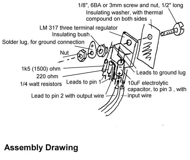
You may need to open the hole in the metal tab of the LM 317 to fit this bush. Also you might need to trim the flange of the bush to clear the molded plastic of the LM 317. The bush will probably stick out beyond the tab and this must also be trimmed.
Now carefully solder the electronic bits together, using the LM 317's pins as terminals. Make sure that you get the polarity of the electrolytic capacitor right, the – (negative) end goes to ground. Check how long the pins of the LM 317 can be and still fit into the case, without shorting anywhere. When soldering is completed place plastic tubing over the joins and pins to make sure that you don't get a short.
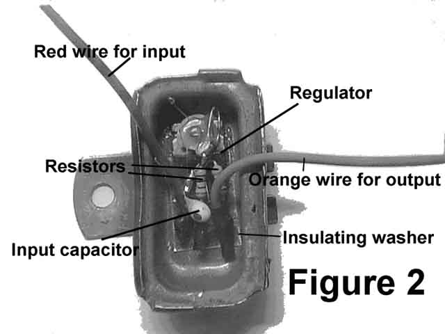
Mount the whole lot in the case applying thermal compound to both sides of the insulating washer and test that you don't have a short between the LM 317's metal tab and the metal case and that the ground lug does connect to the metal case, through the mounting screw. When all assembled and checked, lock the fixing nut to the screw with a touch of glue or nail polish. Solder the resistor and capacitor leads to the ground lug. Solder the input wire to the rivet of the spade lug on the fibre board marked B (I used red wire) and the output to the rivet of the spade lug marked I, (I used orange wire) see Figure 2.
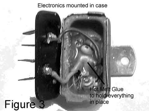
You can test the device by using a battery or charger, making sure that the positive is connected to the input and the negative is connected to the metal case. The output should measure around 10V. If this test is OK then the components need to be physically anchored to resist vibration, which could cause the leads to fracture. I used hot melt glue, but even dripping candle wax over and through them should do the trick. See Figure 3.
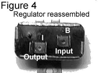
Now fit the fibre board back onto the metal case, making sure that no shorts are created and re-crimp the lip around it, Figure 4.
Refit to the car, ensuring that the input B and output I are connected correctly. The only drawback with this mod. is that the gauge will be a bit slower, reaching its reading, when the ignition is first switched on.
NOTE: This regulator is only suitable for NEGATIVE ground cars.