
by Herb Adler 5243 3409
Keyless door entry
If you remember last episode I described how I ran wires into the doors for the keyless entry system. In this episode I will describe the fitting of the mechanical parts.
The first mistake I made was to do the slave, or passenger door first. This left me with embarrassingly short lengths of wires in the master or driver's door. Doing it the other way would have given me all the wire length I needed as the slave wires were far too long anyway and were cut and reterminated.
The first items, apart from the door locking system, that I bought were some rod lock clips, I think that's what they were called. They determined the size of the control rods I would need, 5mm as it turned out.
As I have two different styles of doors there are some differences in the installation methods. In hindsight both doors could have been done as in Figure 7, but this was the driver's door.
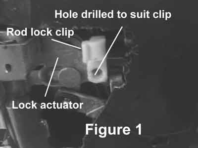
The first thing was to determine how the rods were to be
connected to the lock actuators, ( the little plates that somehow
do the locking). In the passenger door I needed to drill a hole
in front of the existing locking mechanism, as in Figure 1, whilst
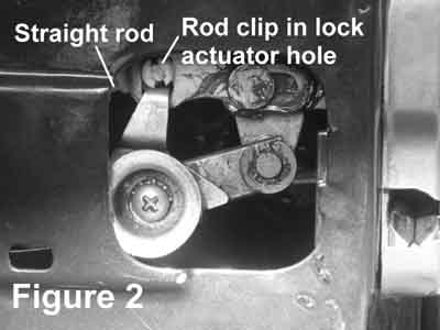
in the driver's door the hole for this existing mechanism is large
enough for the rod clip to fit, as in Figure 2
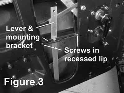
The most critical part is the lever between the electric actuator
and the lock actuator. The electric actuator has a movement of
16mm, whilst the lock actuator only moves 8mm. This required
that the holes for the rods had to be spaced from the pivot
point at a ratio of 2 to 1. The pivot point is a hole drilled and
tapped to Ľ”, screwed onto a Ľ” bolt, which in turn is bolted to
a cross member, as shown in Figure 3.
The two connecting rods were also different, the one for the
passenger door needed to be bent up to clear the existing
mechanism, Figure 4
Whilst the driver side rod could be straight
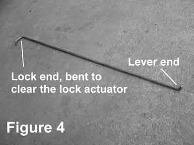
Figure 5 shows part of the final assembly in the passenger
door. Note that the lever had to be bent outward a bit, to clear
the window mechanism. Also visible is the pivot bolt and the
nut holding it.
The complete final assembly is shown in Figure 6.
Note that all screws have been drilled through the recessed lip
on the doors so that they would not cause bulges in the trim.
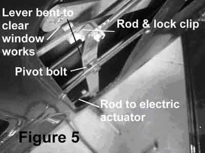
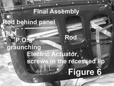
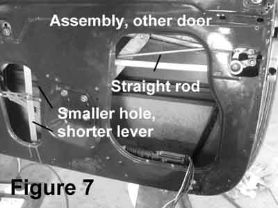
Figure 7 shows the final assembly of the driver's door. Note
that the hole in the door is much smaller, necessitating a
shorter lever, still with the 2 to 1 ratio between the pivot and
rod holes.
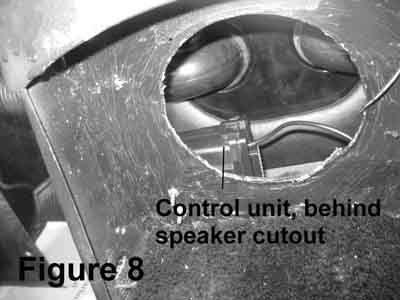
The electronic control box was fitted behind the central radio
speaker cut out, as in Figure 8.