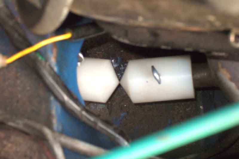
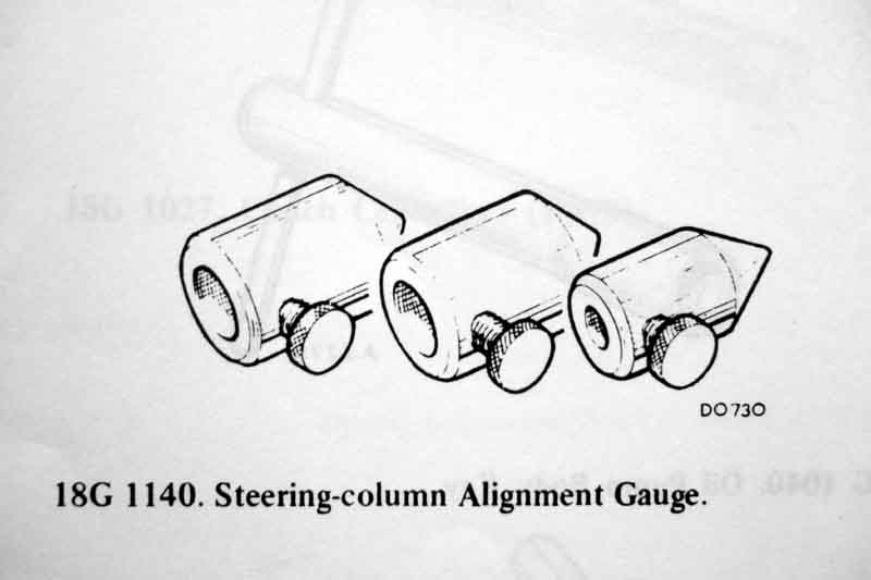
The tool shown in the Leyland Workshop Manual
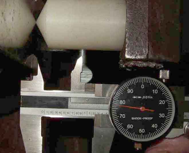
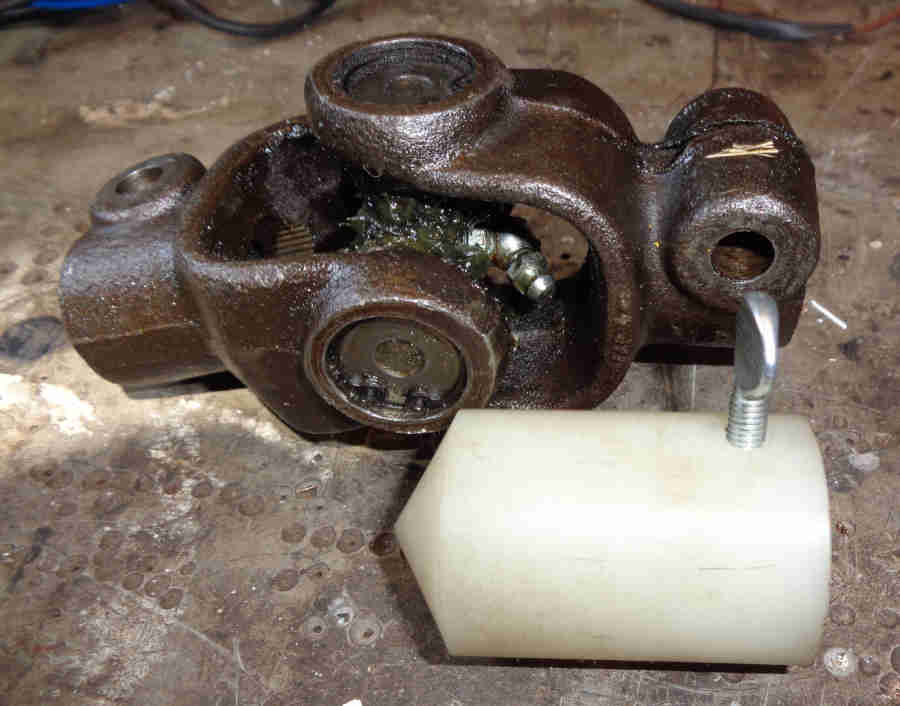
Re-measuring my new RB V8 UJ - 1.2415" or 31.5mm. Done more carefully than before, I have laid a white pencil in the bolt holes so it will be lying at the bottom of the hole i.e. the middle of the pencil should equate to the middle of the hole. One caliper finger is over the middle of the pencil, and the other is resting in the middle of the spider, as judged from the concentric rings on the end-face of the cup:

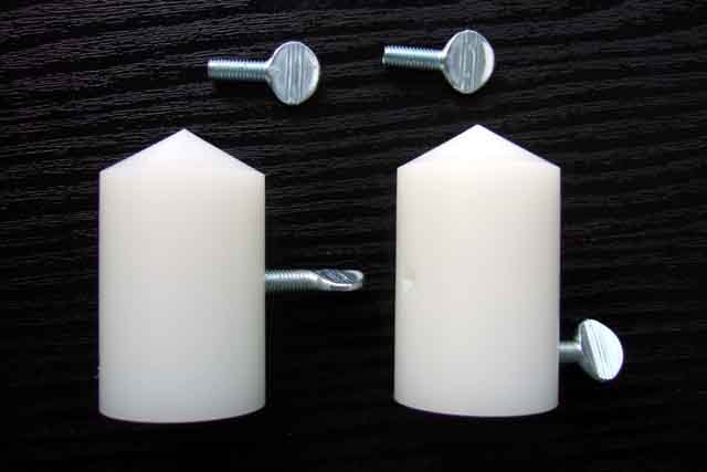
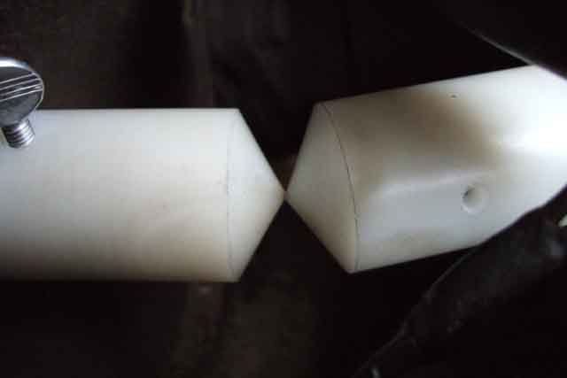
The Moss tool as received, showing the relative positions of the two holes:
Measuring from the tip to the centre of each hole 1.755" or 44.58mm ...

... and 1.177" or 30mm, so 1.5mm out for the RB UJ:
Hole nearest the open end for the roadster:
About 1/8" misalignment on the roadster:
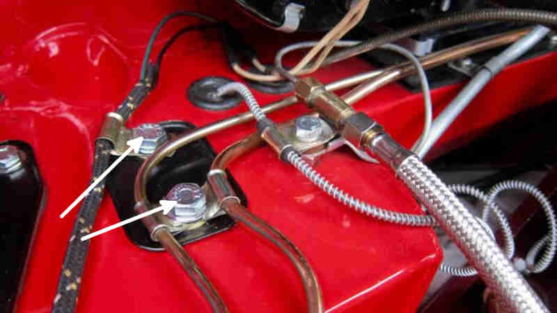
Early and Mid-era columns: The column outer clamps 'A' and 'B', and the concertina bulkhead seal 'C'. 'A' only allows up and down movement, 'B' allows up and down when the nut here is slackened ...
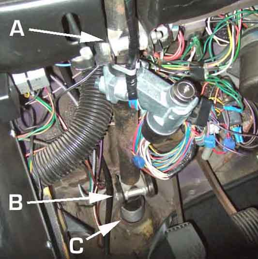
... and when these two screws on top of the heater shelf are slackened the whole lower bracket and clamp assembly will slide from side to side for horizontal alignment: (MGE)
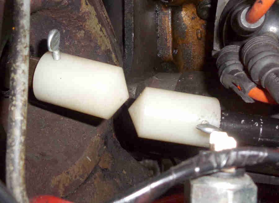
With the Bee's new rack the initial misalignment is a lot more in both vertical and horizontal directions:
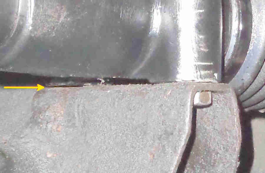
There is enough movement in the lower column bracket to correct the horizontal but not enough in either of the column brackets to correct the vertical so the upper mounting points on the new rack will have to be shimmed. As well as all that the four rack mounting points need to sit square to the cross-member brackets and with the new rack (at least, I didn't have cause to check the old rack) the upper end of the near-side has a 12 thou gap to the bracket with the other three bolts nipped up:
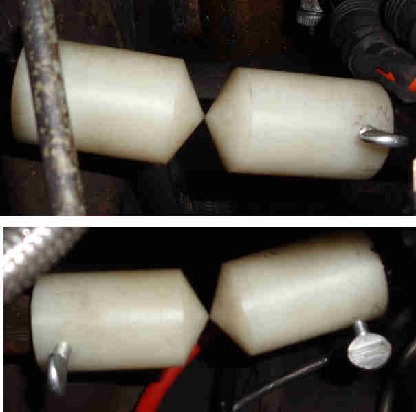
Several hours later, aligned from two angles about 90 degrees apart:
The inners slide up and down in the outers so the rack and UJ set the position of the wheel relative to the dash. Because the outer can be moved independently of the inner and the cowl and indicator switch positions are determined by the position of the outer, the outer needs to be slid up and down in the under-dash brackets to get the correct overlap between cowl and wheel. But note slackening either of the clamp bolts is likely to lose the alignment to the rack shaft so the two should be realigned afterwards:
73 roadster and 75 V8 column shafts only have a notch for the UJ clamp bolt meaning the UJ can be attached to it in only one rotational position:
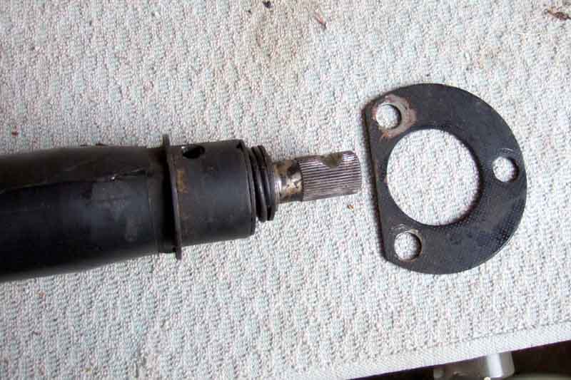
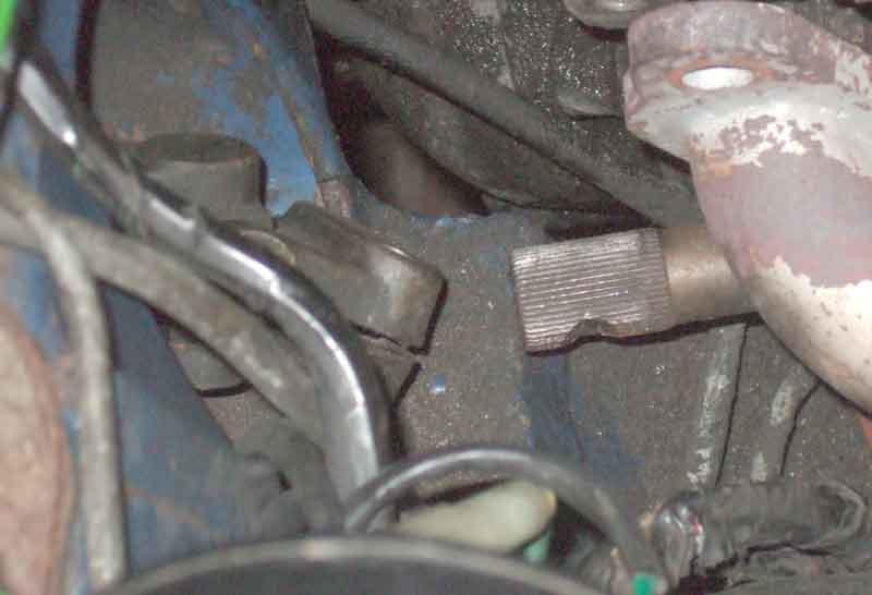
But whereas the roadster rack shaft has a groove all the way round meaning it can be fitted to the UJ in any rotational position to suit steering wheel alignment (plus fine-tuning with the track-rod ends on the track-rods), the V8 rack shaft also has a notch! This means that you can only correct steering wheel alignment by a combination of the position of the wheel on the shaft and the relative positions of the track-rod ends on the track-rods. However that does mean that the indicator cancelling cam is always in the same position on reassembly, whereas with the groove that may need altering as well.
Later full energy-absorbing column: The UJ controls the position of the inner, and as the relative position of inner and outer is fixed by the upper bearing the UJ also controls the position of the outer and hence the column brackets 'B' relative to the body mounting points, the slots in the column brackets are solely to deal with dimensional variations from body to body. The bolts go into caged nuts so offer some side to side adjustment of that end of the column, and spacers at the lower single, or upper pair of slots, allow the column to tilt:
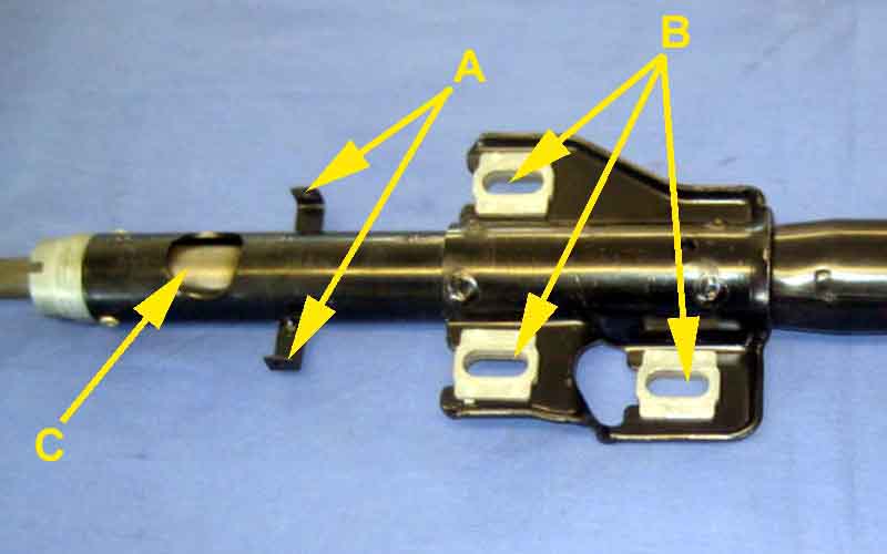
Plate (A), seal (B) and alignment gauge attached to column before refitting. Subsequently I chose to attach the plate and seal to the toe-board first, then push the alignment gauge (screw removed) on the end of the shaft through them. The plate at the bottom of the column is only tightened to the toe-board once the column has been aligned, it should not be used to force that end of the column into the correct position:
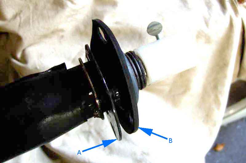
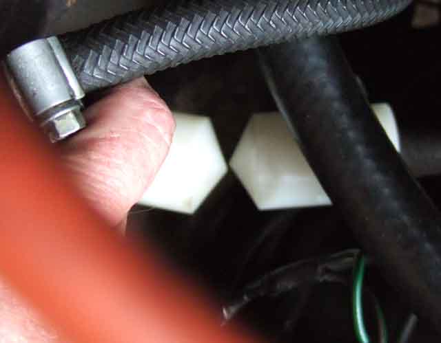
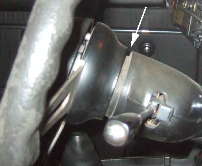
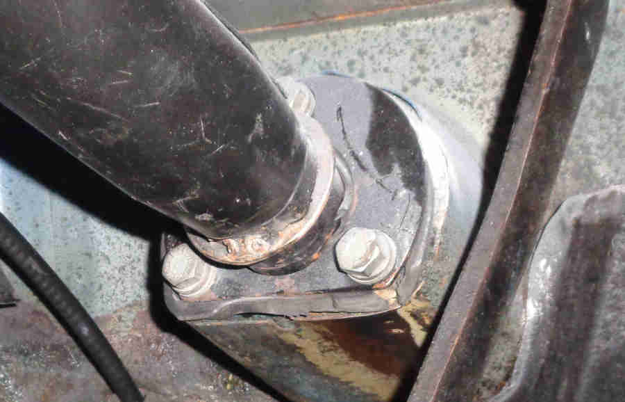
Plate and seal screwed to the toe-board, the collar (a bit chewed) of the seal is visible in the gap between the column outer and the hole in the seal. The screws should be loosely fitted before aligning column and rack, tightened afterwards with the gauges still on the shafts to ensure you haven't moved that end of the column:
Column aligned: