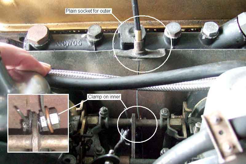
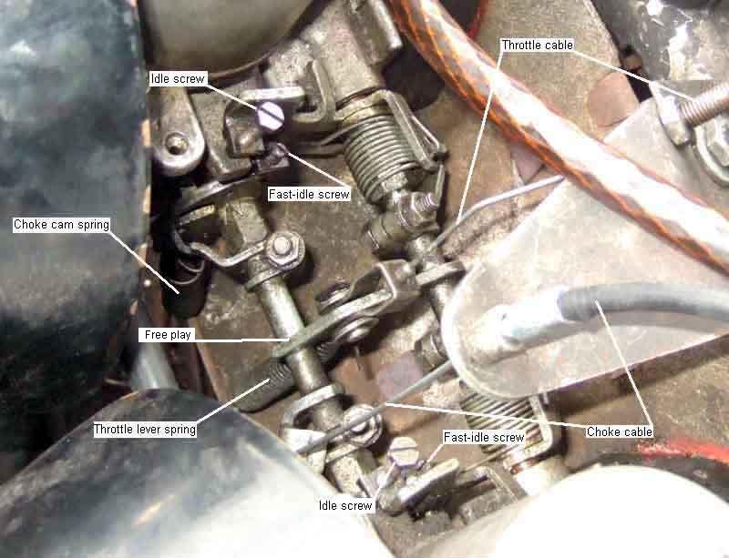
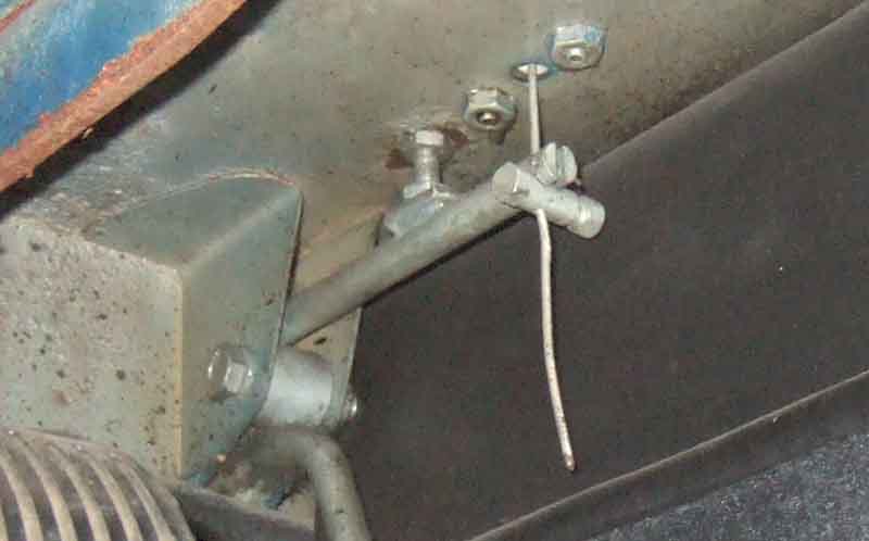
The earlier arrangement (HS carbs on LHD cars, all chrome bumper UK cars) uses a plain socket for the outer and a clamp for the free end of the throttle cable at the carbs. This uses a special stud consisting of a hex nut with a threaded stud on one side and a plain stud on the other, both having a small hole drilled through them across the line of the studs. The plain stud goes through a hole in the finger on the throttle interconnecting shaft, then the hook-plate for the return spring, and a washer, and is secured with a split-pin. The free end of the cable goes through the hole in the threaded stud, a washer goes on top, and a nut on top of that, these last two clamping the cable and adjusting for cable length. There are flats somewhere on the special stud to allow you to hold it with a thin spanner whilst tightening the nut. This arrangement has the choke cable coming up from below, with a moving outer and a fixed inner. Note this continued on RHD cars until the 77 model year:
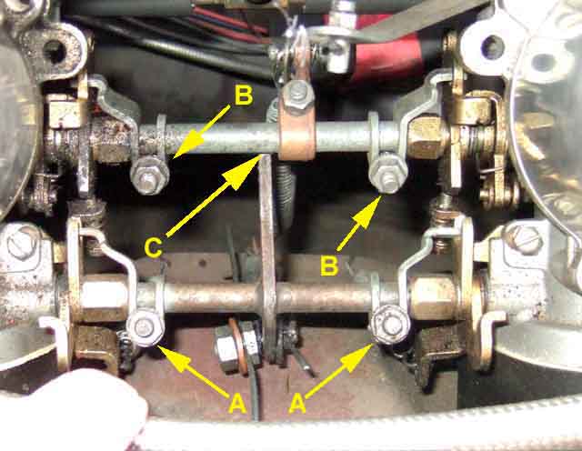
View from the RHS of the car leaning over the engine. The choke linkage is towards the top of the picture (with return spring) and the throttle at the bottom. There should be 12 thou free play between the throttle interconnecting shaft finger and the choke interconnecting shaft at the point indicated, to ensure the throttle butterflies are on the idle screws and not hanging on the cable:
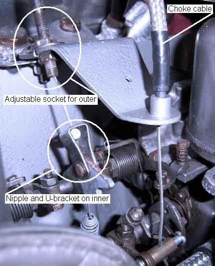
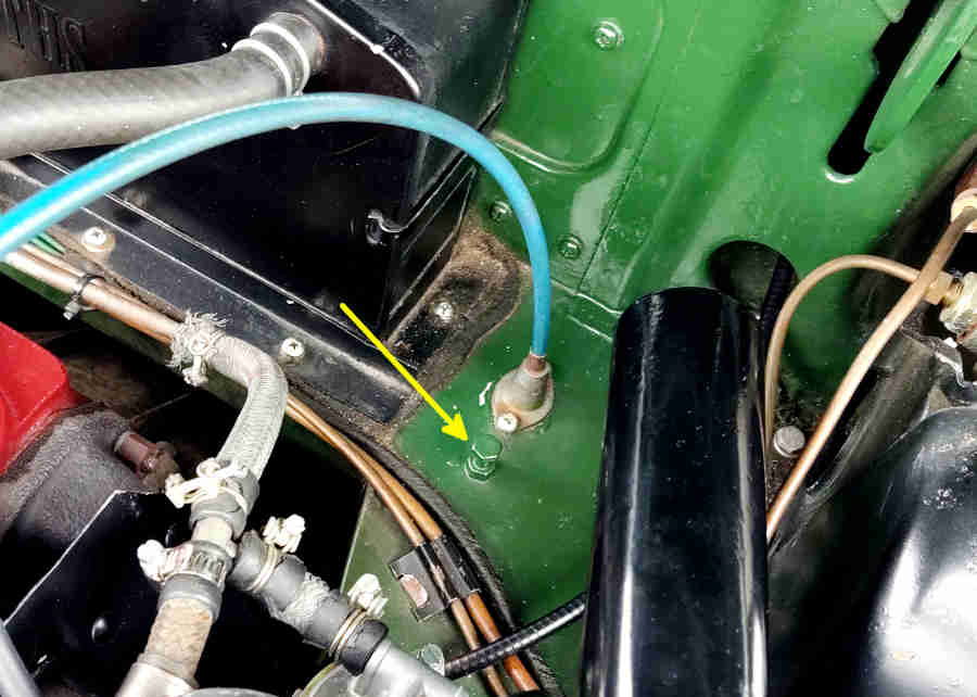
The later arrangement (HIF LHD cars and rubber bumper UK cars). On these the throttle cable comes with nipples on both ends, and a 'U'-bracket on the carb end. There is a threaded adjuster for the outer to adjust for cable length, and the support bracket is slotted at the adjuster to allow cable replacement. This arrangement has the choke cable coming down from above and the more conventional fixed outer and moving inner. Note this shows the throttle partly operated for clarity, when at rest there should only be a very small clearance between the 'finger' on the throttle interconnecting shaft and the choke interconnecting shaft (see 'SU Carbs' and 'Setting-up' for details): (Scott Loehning)
There should be 12 thou free play between the throttle interconnecting shaft finger and the choke interconnecting shaft at the point indicated, to ensure the throttle butterflies are on the idle screws and not hanging on the cable:
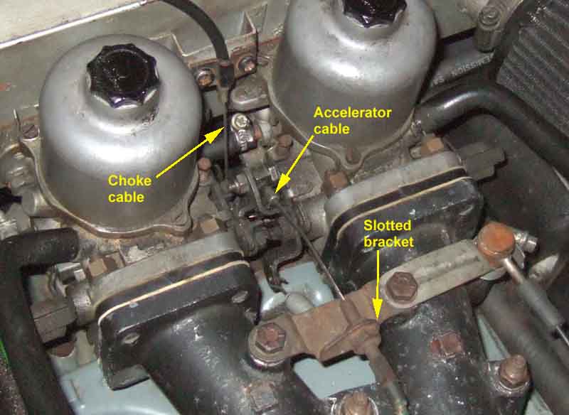
V8. The choke cable has a ball-shaped nipple moulded on which engages in a slotted trunnion. The accelerator has a large rectangular fitting with a bolt through it and the carb lever, and the bracket for the adjustable outer is slotted to allow cable replacement as on the HIF. There is no measurement point for free-play in the throttle cable but there should be 1/16"of movement of the cable before the butterflies start to open:
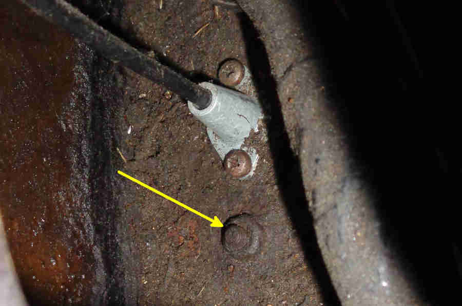
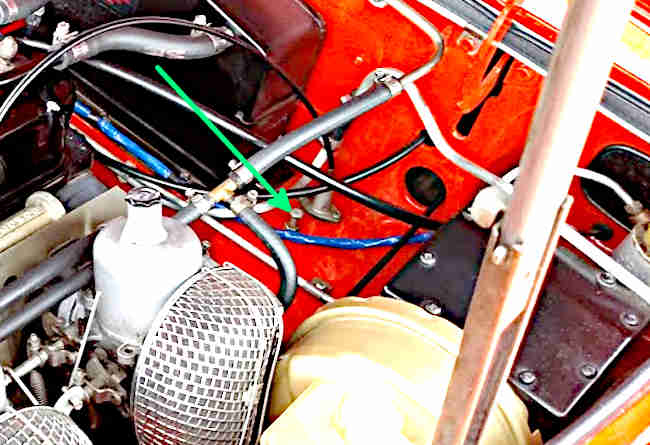
Throttle cable guide AHH5308 (uses seal ACA5073) on the bulkhead. According to the Parts Catalogue only one part number fitted to all cars i.e. not slotted or pre-fitted to the cable for 4-cylinder HIF cables. Note the pedal back-stop screw (next image) fitted from underneath the shelf arrowed:
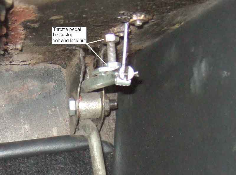
Throttle pedal back-stop bolt and lock-nut used as part of cable adjustment. The bolt screws up into a welded nut on top of the 'shelf' above the pedal (arrowed above), the locknut tightening up to the shelf to secure the bolt. With the pedal released the cable should have no tension such that the butterflies are on their idle screws and there is the prescribed free-play at the carb end. When fully depressed the pedal should just fully open the carbs but not be stretching the cable. RHD HS shown here but the adjustment applies to all versions. The cable is retained in the slot in the pedal arm by a split-pin to prevent the nipple becoming detached if the there is too much free-play with the pedal released. To replace an HS cable the old inner has to be pulled out from the footwell and the new one fed up through the bulkhead and guide, then the outer refitted in the engine compartment:
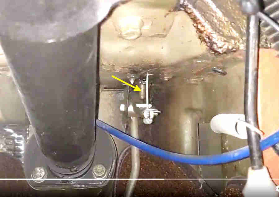
LHD cable guide and pedal back-stop (arrowed) on the heater shelf. In this case the welded nut is under the shelf and the screw with lock-nut goes down through the panel:
From 1975 when LHD cars gained the boosted dual-circuit system the cable guide (and hence back-stop) was moved a couple of inches closer to the vertical bulkhead which meant the cable guide had to be turned through 90 degrees to get space for the fixing screws. So far I have not discovered a reason for that, the distance between the pivot and the cable attachment is within 1/4" on both types of pedal so it's not a case of the Zenith (albeit SUs retro-fitted here on a 75/76 model) needing more cable movement for full travel. Pedal pad position? Pedal arm to pad shape different? Who knows? RHD cable guide position does not appear to have moved between the two pedal types:
Welded nut under the panel and the threaded end of the screw should just touch the plate on top of the pedal shaft, without applying any force to the cable:
RHD HIF arrangement. The carb end has a nipple and bracket, and there is another nipple at the pedal end, so the inner cannot be removed from the outer, the two have to be replaced as a pair. The hole in the guide (and bulkhead) have to be large enough to allow the spherical nipple at this end to pass through, but small enough to retain the ferrule at the end of the outer:
V8. Plain cable at the pedal end, with a trunnion and split-pin retainer. A pivot and adjuster at the carb end means the cable can be fitted as a single unit, feeding the plain end of the inner down through guide and bulkhead. It makes you wonder why they bothered doing anything else, especially for the 4-cylinder HIF:
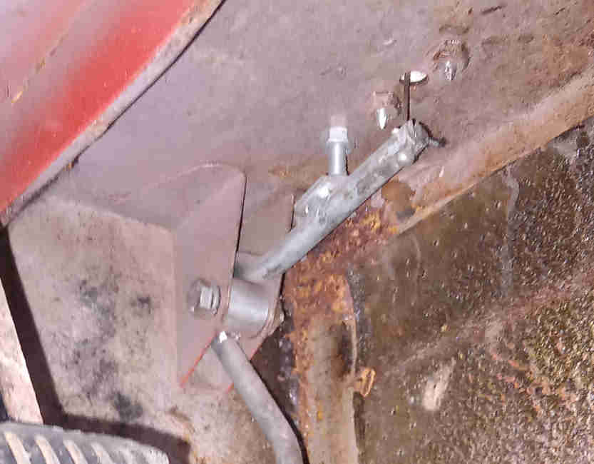
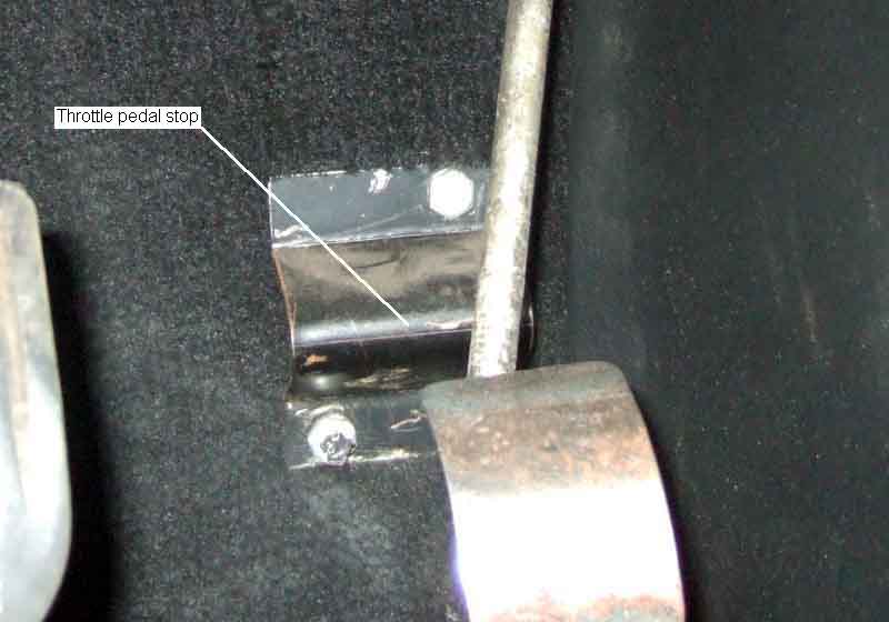
Throttle pedal stop (LHD HS and CB HIF cars, up to 76 UK cars). Missing from the roadster when I received it, I made this from a bit of spare metal based on a rotten one obtained from a scrapper, the bolts screw into welded nuts on the toe-board. Before clamping the cable at the carb end slacken the back-stop lock-nut and screw in (RHD)/out (LHD) the bolt until it is clear of the pedal. Set the clamp (chrome bumper) or outer adjuster (rubber bumper) at the carb end so the pedal hits the stop just as the carbs are fully opened, you want to be able to just fully open the carbs, but not stretch the cable. The pedal should now be floppy when released, screw the bolt down until it takes up almost all of the play, leaving just perceptible free play i.e. not pulling on the cable, before tightening the lock-nut:
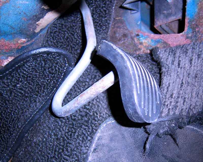
At some time the shape of the throttle pedal was changed to include this 'V' pointing backwards which makes the separate pedal stop unnecessary. However the point of the 'V' is pressing against carpet so you have to be sure that the cable is adjusted such that when pressing down very hard on the pedal the cable is not being stretched. The Parts Catalogue indicates this pedal was for 77 and later cars for all markets, but it seems to have been earlier for LHD cars i.e. from the start of rubber bumpers. Moss.com i.e. North American spec shows one pedal for 1974 1/2 models (HIF), another for 75/76 models and a third for 77-80 models (both Zenith). The one shown here has the same sized metal pad as the clutch and brake which is probably why it shows a rubber pad, which isn't shown in the Parts Catalogue (only for Mk1 cars with a smaller metal pad): (Photo: Scott Loehning)
The 'V' shaped pedal fitted for 77 on both RHD and LHD got a much longer metal pad to aid 'heel and toe' changes, again with no rubber pad:
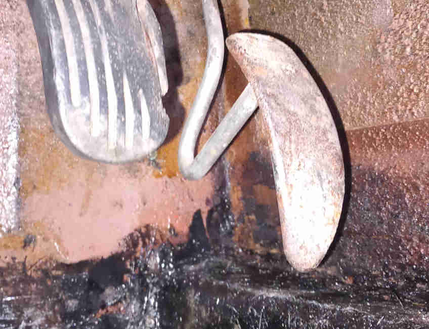
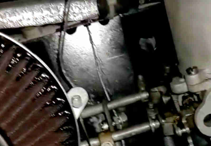
It's important that the throttle pedal hits its stop fractionally before the carbs reach the fully open position or you can get broken strands as may have happened here. Particularly so with the late pedal above where under very hard pressure the pedal will sink into the carpet more than with 'normal' driving pressure: