4-cylinder V8
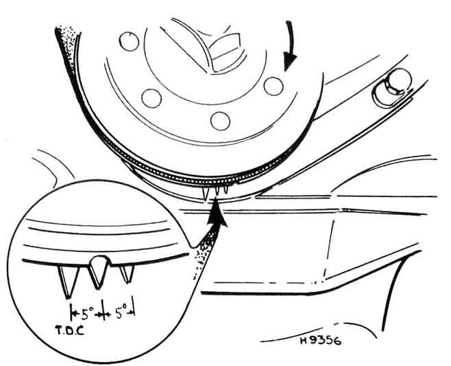
The earliest arrangement - pointers below, but only at TDC, and 5 and 10 degrees before (Haynes).
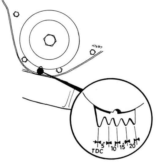
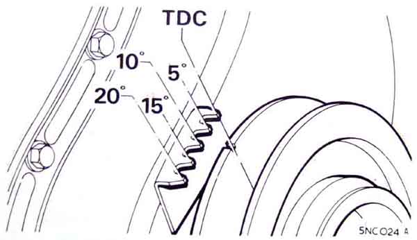
Haynes calls this 'later arrangement' but it still has the pointers below, but additionally at 15 and 20 degrees BTDC (Haynes). This is the only arrangement that my workshop manual shows.
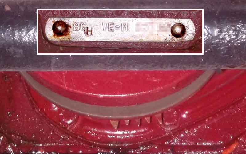
This on a 1970 18GH from Bill Etter has five, of varying height, but with the first one seeming to be the longest instead of the last. From the Parts Catalogue 18GJ would be the same, although by this time non-North American 18GG and GK engines had the timing marks on top:
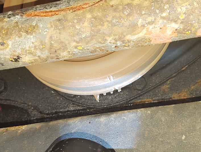
Peter Basher writing on the MGOC MGB Technical forum shows this version on his 1970 which appears to have four pointers. Going by Bill Etter's it could be that the first pointer (closest to the cover bolt) has been snapped off, possibly because being large it was confusing as to which was TDC! Engine number not known but from October 68 non-North American engines should have had the pointers on top:
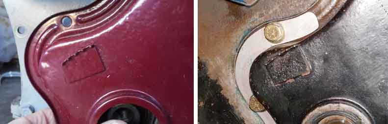
The later arrangement - probably on all 18V engines - above and angled towards the alternator: (Leyland Workshop Manual)
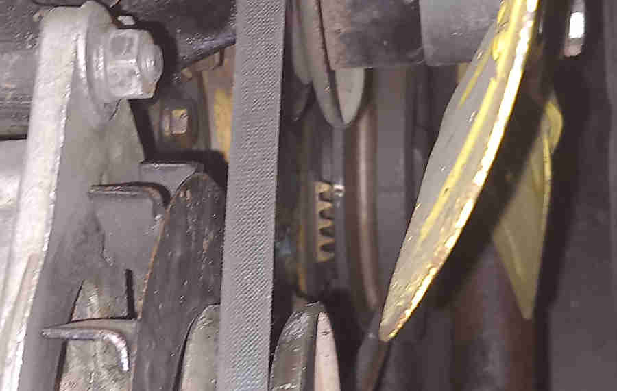
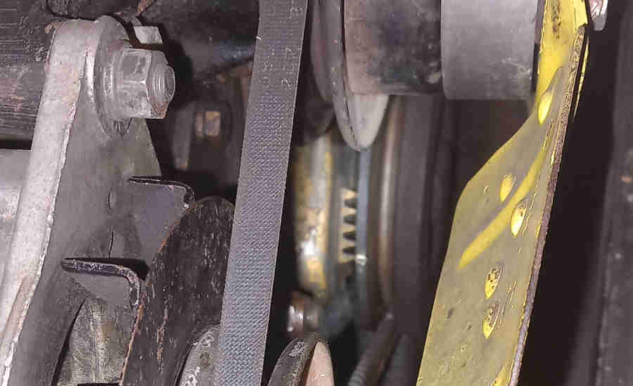
Even then there were two different positions - most CB on the left and late CB (18V779/780) and RB on the right because they had a larger crank pulley so the pointers were moved further out (from the Parts Catalogue, Clausager indicates this change didn't occur until the RB engines 18V846/847/836/837):
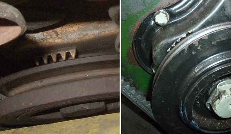
And there's more. Difficult to show on a CB (left) because of the closeness of the radiator but the pointers on that are about 5mm further out from the circumference of the pulley, whereas on the RB (right, John Pinna) they barely clear it:
Practical considerations: September 2023
Given that each pointer to the next represents 5 degrees this is very nearly at TDC! Wondering about slop in the mechanism I took the cap off. I found the rotor was fully at it's rest position, with the springs (replaced in my time) returning it almost all the way back when rotated by hand. Out of interest I checked the static timing with it fully advanced against the springs which gave 20 degrees:
However thinking about it later on if the strobe was supposed to be 20 at 1000 and I was getting 12 then it's hardly surprising that the static had reduced by a similar amount from 10 degrees to close to TDC.
Having a 25D4 with Vernier adjuster I advanced that 10 clicks at a time until I got to 16 degrees at 1k and 28 degrees at 2k, then checking the static again it was about 9 degrees and I'm guessing around 30 when fully advanced manually by twisting the rotor:
A bit of a run and loading up the engine showed no pinking, needs more running and perhaps more heat to be sure.
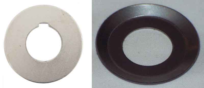
Crank pulley bolt lock washer:
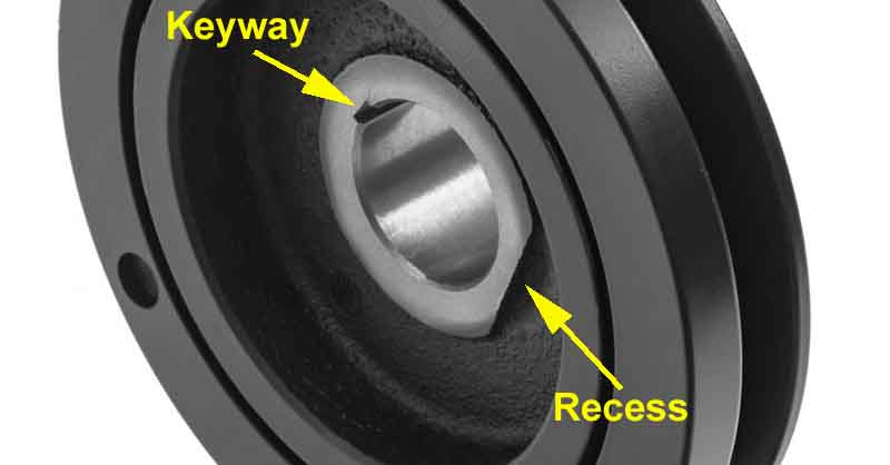
Crankshaft pulley with keyway and recess: (Moss Europe)
The flat type seems to key to the crank then the other side is bent up to key to a bolt flat. The dished type is bent down to lock into the recess on one side and bent up to key to a bolt flat on the other, and the flat type can be locked in the same way if there is no key. If there is a crank key and it extends past the face of the pulley then the dished type would need a keyway to be filed out. However if the key extends past the lock washer then it may prevent the bolt tightening the pulley onto the crank. It seems more likely that the key would not extend past the face of the pulley, meaning either type can be used but both would have to be bent down into the recess and up to a bolt flat.
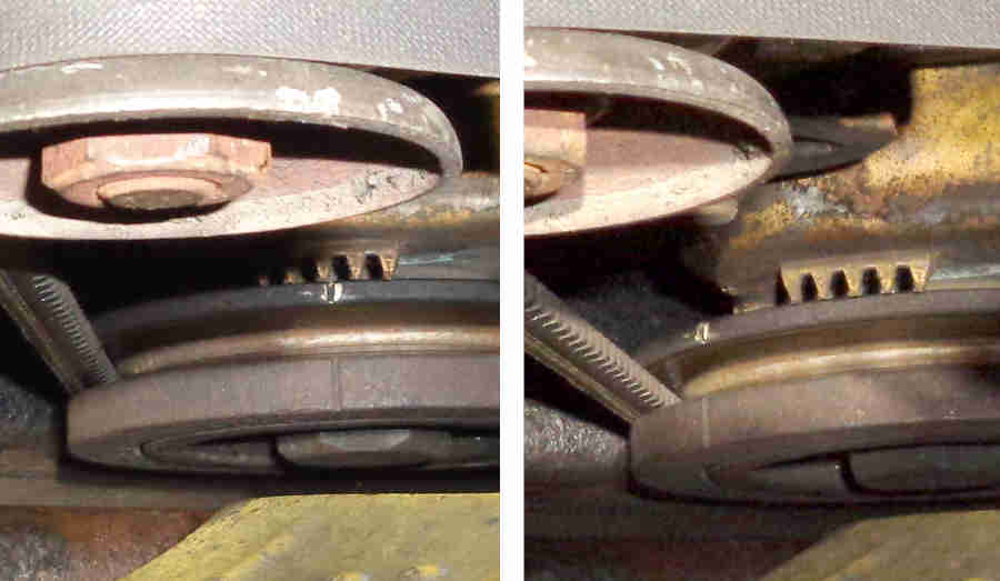
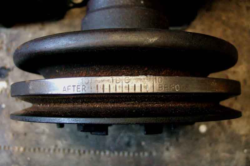
The single pointer is adjustable, which on the face of it is simply to cater for different pulley sizes ... but!
You can clearly see that when looking directly down on the pulley markings, there is a difference of about five degrees between fully out and fully in, which would have a significant effect on timing. My pointer was set fully in i.e. close to the pulley, but I'll have to check what that represents as far as true TDC goes.
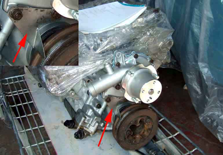
Although I bought a modified timing pointer from Rimmers I can't find any way of mounting it to the new front cover, so have to fabricate my own. With the old engine, front cover and water pump at home, I decide to best place to mount one is on two of the lower water pump bolts - one that goes right through the front cover and the other just into it. With the original pointer (which I had lost, but found again when it came back with various bits from the engine man this week) I was able to make a card template, and from that cut one out of sheet metal. With the pulley (which I now have back as well) in the front cover I turn that so the original pointer is over the TDC mark then remove that and fit the new one, for final tweaking of bolt holes and pointer angle to be in the same position. As the water pump and crank are in the same positions relative to each other on both old and new covers, the new pointer does the job.
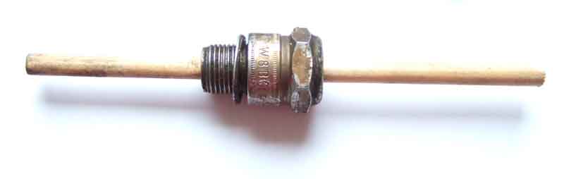
Checking timing marks and adjusting the V8 pointer: Knock the ceramic insulator out of an old plug and insert a length of dowel. I was considering fixing the dowel in position, but opted to leave it sliding (but not loose) and marking it instead.