
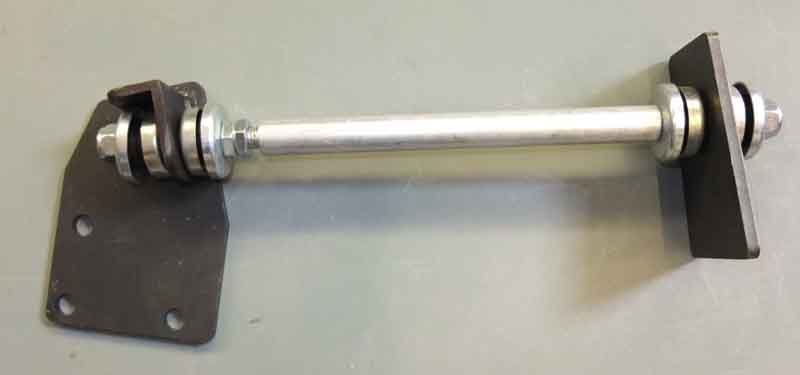
Engine steady from Clive Wheatley:
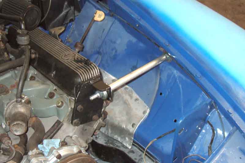
Installed, after engine bay paint but before external paint:
However it was only when writing this section and getting a photo of the steady as supplied from Clive's web site that I realised mine was installed the wrong way round i.e. with the adjuster nuts against the inner wing. I remember being aware when refitting it after the repaint that having them there was awkward, especially being ultra careful with the new paint. I wouldn't have completely dismantled that when removing the bar to get the engine and gearbox out, so I must have installed it that way to begin with, and Clive's people said they send them out loosely assembled. The bracket end has to be assembled before fitting - with the distributor in-situ at any rate, as you can't install the bare bar to the wing then fit the bracket to the bar.
So at an opportune moment I corrected it - but it was a right pain. The under-wing nut and fittings have to be removed first, then the cylinder head bolts or the bracket flops about all over the place while dealing with the under-wing nut, and it also holds the bar still while spannering the Nyloc nut off - the threaded section could do with being shorter. Then the distributor cap had to be removed, but even then the bracket had to be fiddled past the distributor body, it doesn't lift straight out (or back in).
Undid the nut at the bracket end and put that at the other end, refitting that nut loosely. Fiddling it back into position even with the adjuster nuts all the way back, with one bracket bolt in the cylinder head the other two bolt holes were miles out of line, and I had to fully tighten the nut under the wing to squash to rubbers together, and almost fully tighten the nut at the bracket which was the only way to get the holes in the bracket anywhere near the head holes, before I could get the other two head bolts in. In the main section I write that the fore and aft position on the wing isn't critical, which it isn't, but when fully tightening the under-wing nut that pulls the bar into a right-angle with the wing panel, but as the engine bay gets wider as you go back, that has the effect of pointing the bar backwards slightly, which presses the bracket hard up against the end of the head, and turns it at an angle to the head. To position the lifting eye (which I have retained behind the bracket for obvious reasons.
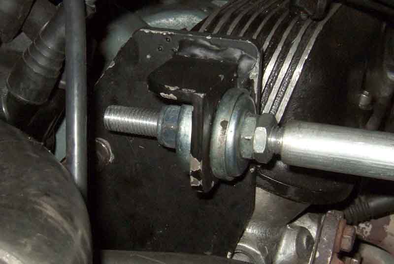
Adjustment is another fiddle as when either the main nut or the adjuster nuts are backed off, the rubber bushes expand, and if left like that the engine will still rock, so the rubber bushes have to be clamped up tight at that end as well as at the wing. The only way I can see to do it (I don't have Clive's instructions anymore which is unusual, I normally keep all such things together) is by tightening up both nuts together until both are just touching their respective bush cover, then tighten them together in unison one flat at a time, to keep the engine 'square'. If you don't do that then you will be pulling the engine towards the left or pushing it to the right, which you may choose to do anyway to get an equal clearance of both manifolds to the inner wings. Finally tighten the locknut! You can see from this how little room for adjustment there actually is, and that's with the bushes at both ends fully compressed. There is no way I could get the bolts into the cylinder head without doing that first:
And it's done:
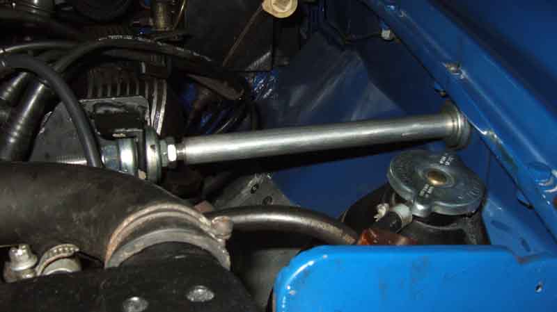
Really the length of the threads under the wing is longer than it needs to be, as is the plain section in the middle, which makes the threaded section at the bracket way too long as well. The plain section could easily be an inch shorter (on my car at least) with the threaded section that end unchanged, and that would make fitting much easier. To my mind you should be able to get the three head bolts installed with the engine-end nuts still loose.