
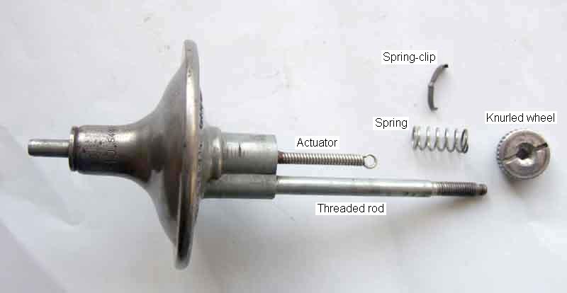
The 25D vacuum module. There is a ridge on the spring-clip that engages with the notches in the knurled wheel to give 'click-stops' for each fraction of a degree of adjustment. The coil spring steadies the vacuum module in the distributor body and prevents vibrations from causing small variations in timing. This is a later 25D with push-on port for rubber and plastic pipe, earlier versions had a threaded boss for a copper pipe with a separation chamber at the carb end. There should also be a small split ring 'circlip' fitted on the end of the threaded rod to stop the knurled wheel turning beyond the fully advanced position. It depends on how many serrations you have around the edge of your knurled wheel, and hence how many clicks for a full turn, but according to this 0.5585 turns of the wheel gives 1 distributor degree, or 24 clicks, and so 12 clicks will give one crankshaft degree. Mine has 35 serrations instead of his 43, and can go through 7 full turns, so if the thread pitch is the same that gives about +- 6 crankshaft degrees of timing adjustment:
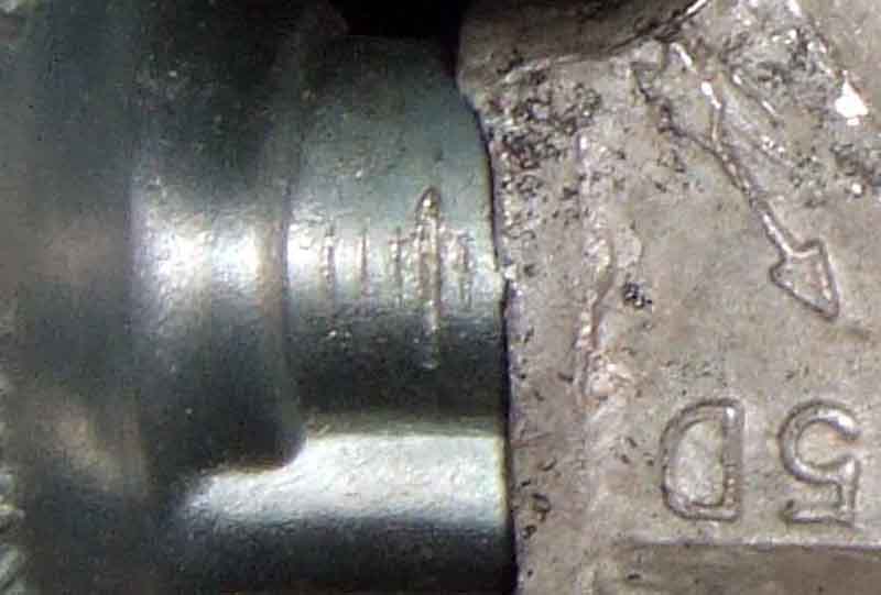
There seem to be a series of engraved lines on the body of the vacuum capsule, exposed progressively as the timing is advanced from a minimum, which may indicate degrees in some way - perhaps 2 degrees per graduation based on the above calculations:
The 25D module adjusted to the fully retarded position with thread showing ...

... and the fully advanced position with no thread showing:
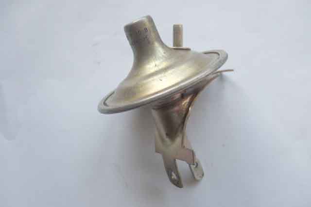
A typical 45D vacuum module, no provision for adjustment other than turning the whole distributor relative to the engine:
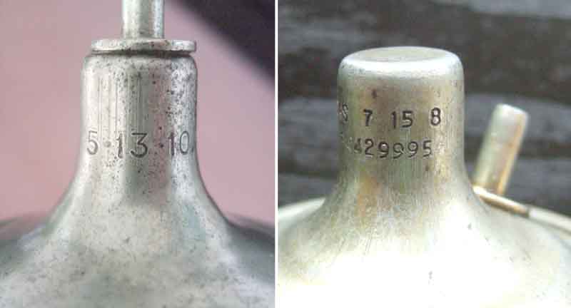
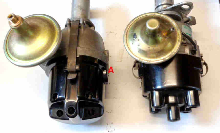
The vacuum advance characteristics stamped into the upper part of the casing of typical 25D (left) and 45D (right) modules. On the 45D it is the '7 15 8' that describe the characteristics. The long number below is the Lucas part number, the 'S' of 'Lucas' being just visible to the left of the characteristics. The first number is the vacuum at which vacuum advance starts to be applied. The second number is the vacuum as which maximum advance is being applied, and the third number is the maximum advance that can be applied in distributor degrees. This doubles when read at the crankshaft markings:
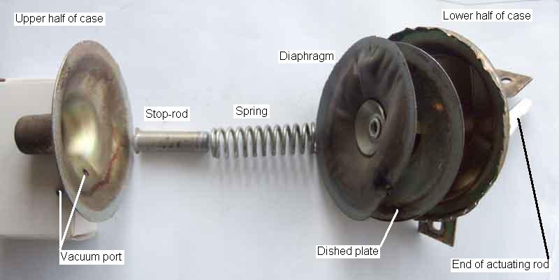
What lies inside, in this case a 45D. I'm not sure what the purpose of the dished plate on the distributor side of the diaphragm is for, the 'at rest' position of the diaphragm is controlled by a step at the top of the actuating lever resting on the inside of the lower half of the case:
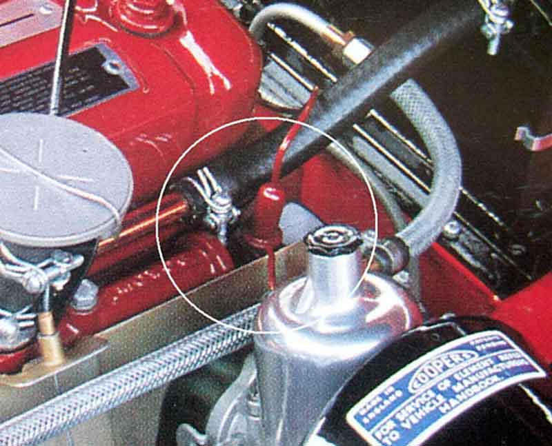
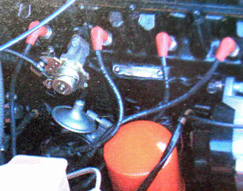
The copper vacuum pipe and 'fuel trap' 12H733 on early 4-cylinder cars: (Clausager)
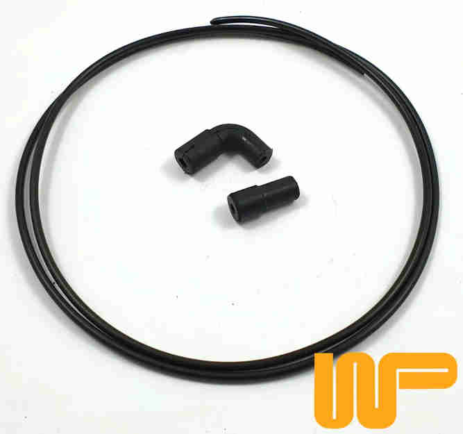
Mk2 cars used a plastic tube 37H4229 with rubber connectors at each end angled 12B2062 at the carb end and straight 12B2095 at the distributor. However this kit from Wood and Pickett is quite a bit cheaper than buying the individual parts from mainstream MGB suppliers and with 1m of tubing is more than enough for the MGB:
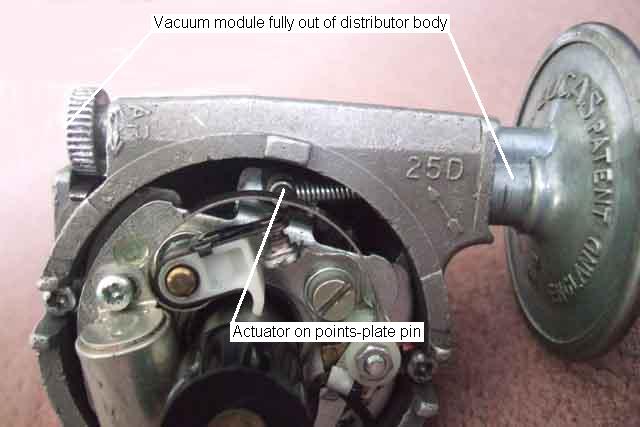
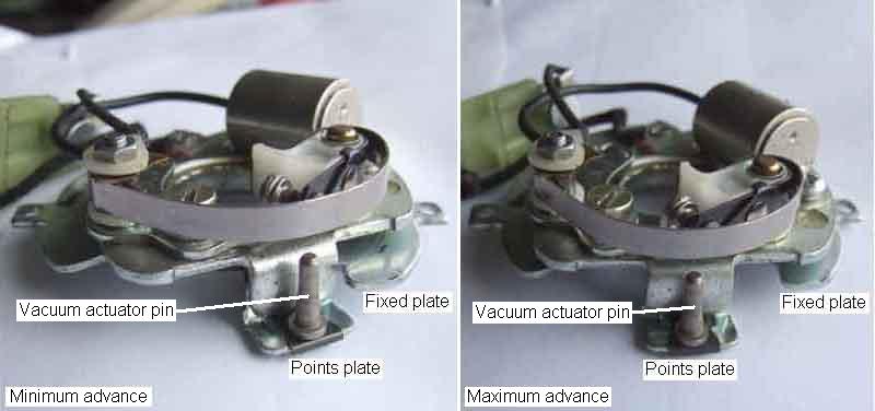
A 25D points plate, showing how the vacuum module actuator pulls it round clockwise to advance timing:
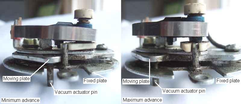
And a 45D points plate ditto. Because the distributor is rotating anti-clockwise, moving the points plate clockwise causes the points cam follower to meet the lobe of the cam earlier to advance timing:
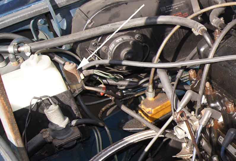
The vacuum solenoid (arrowed) on Bill Etter's 76:
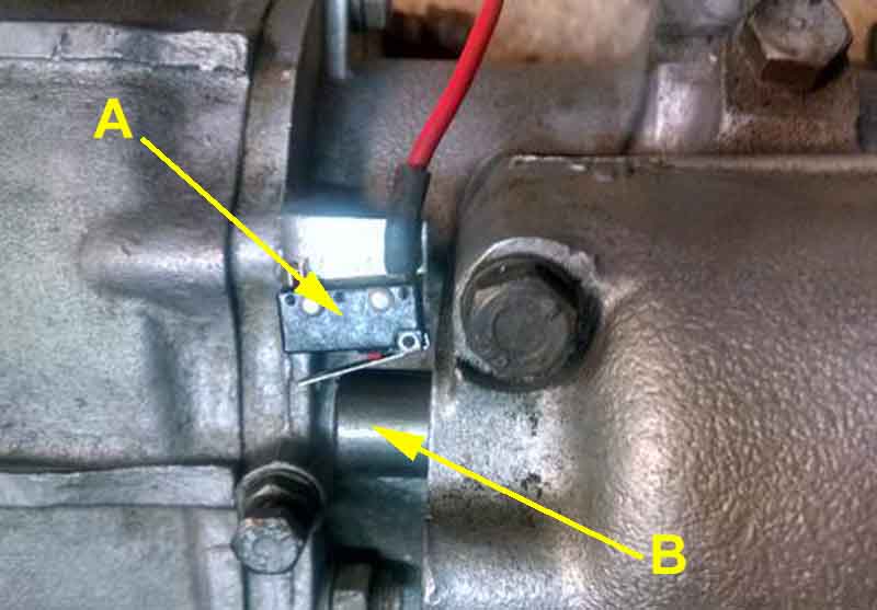
And the microswitch (A) used briefly so OD still worked in 3rd and 4th whereas vacuum advance was only applied in 4th gear. This closed in Reverse, 2nd and 4th when the gear change shaft (B) moved forwards in those gears, and was wired in series (a logic 'AND' gate) with the OD switch which closed in 3rd and 4th, giving the '4th gear only' signal. This was from July 76 to Feb 77 only, after that the microswitch was deleted and the OD switch actuation modified (as per V8s) to operate in 4th gear only, controlling both OD and TCSA:
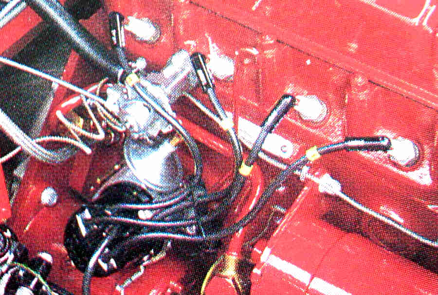
More upright, with the leads probably correct:
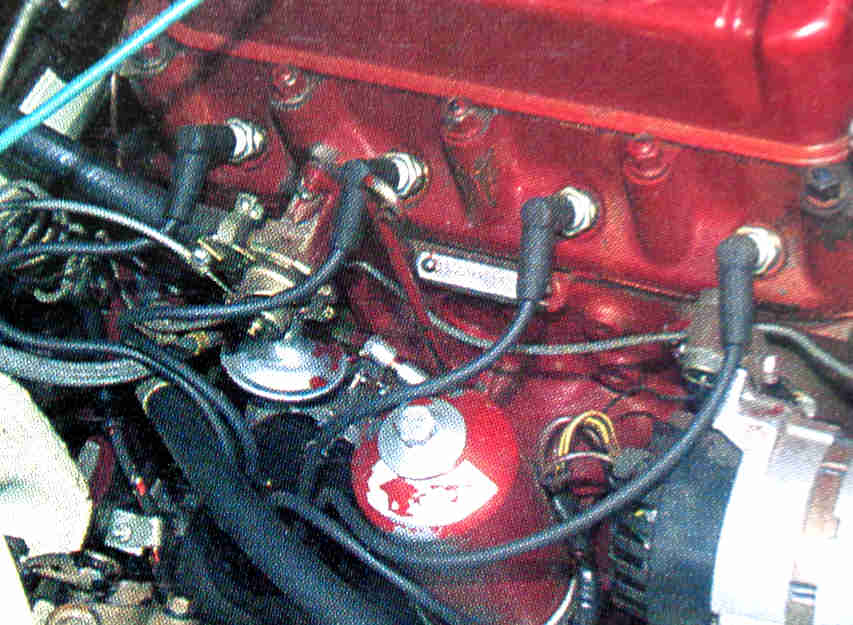
Left of the heater valve and No.4 plug, with the leads correct:
Straight up, leads correct:
To the right of the heater valve, leads correct:
Bee - straight up between the heater valve and No.4 plug. Not shown here but the leads are correct and I know the rotor is pointing to about 2 o'clock when firing No.1 cylinder (ignore the arrow which is for temp gauge capilary mouting purposes):

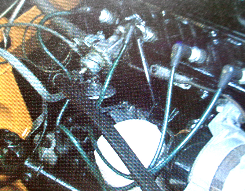
Geoff's pointing wholly to the right! This puts his 45D4 cap clips top and bottom i.e. awkward to get to the bottom clip, so would definitely benefit from being turned 90 degrees anti-clockwise to point up which would put both clips on the sides:

I hadn't realised that, and comparing the two side by side confirms the two distributors are quite different in that respect as well as others - 25D4 on the left with clips top and bottom, 45D4 on the right with clips each side:
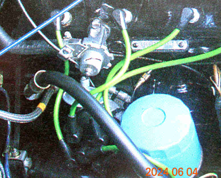
This 25D4 has the early vacuum capsule with the copper pipe from the carb, and side-entry cap. Both aspects mean that really that type does need the capsule pointing up. Top-entry caps means the distributor could be in any orientation (right-angle HT leads being preferable in all cases) but with all 25D4s having the spade connection from the coil on the side at 'A' it is better accessed when it is on the side. At the top would be equally accessible, and improve access to the clips, but that has been shown have the vacuum capsule foul the oil gauge pipe. At the cost of the spade terminal being underneath pointing to the right would give good access to the clips, my first thought was that the capsule would foul the oil filter, but in fact it's more likely to be the dip-stick, although with Geoff's 45D4 the capsule is between the filter and the stick, so maybe worth looking at on my 25D4.