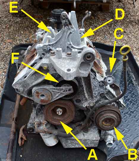
The components around which the auxiliary belt travels: A - crankshaft pulley; B - air-con pump; C - location of idler pulley; D - location of power steering pup; E - location of alternator; F - auxiliary belt tensioner. Sundry engine mount components have to be removed before you can remove the auxiliary belt, then crank pulley, idler pulley, air-con pump, tensioner and dipstick tube before you can remove the front cover to access the primary belt. RubberFusion Engineering
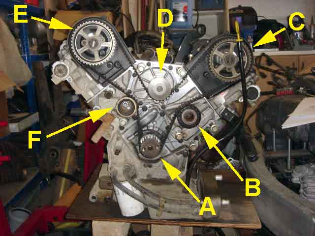
The primary belt: A - crank pulley; B - idler pulley; C - front bank inlet camshaft; D - water pump; E - rear bank inlet camshaft; F - tensioner. XPowerForums.com
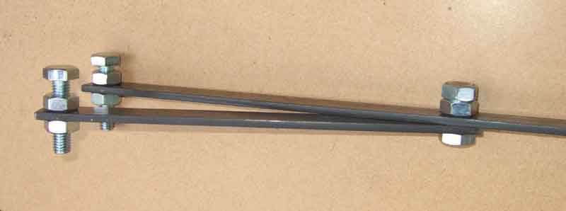
The forked tool. About 8" cut off the flat strip and a set of 10mm (shank) bolts and nuts for the pivot and 'pegs' to engage with the slots in the sprocket. After the other pieces had been cut off the tool ended up being about 2 ft long overall.

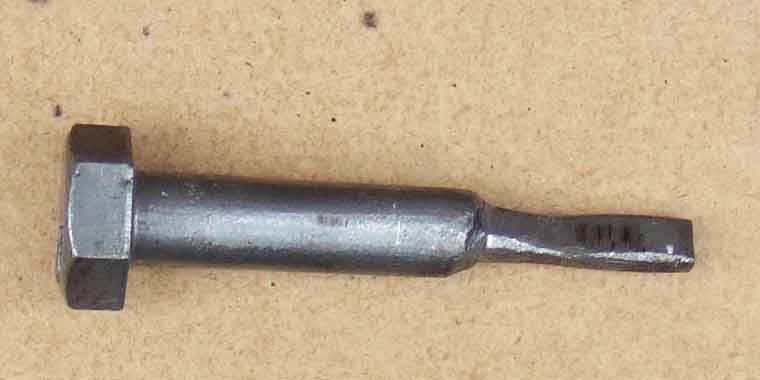
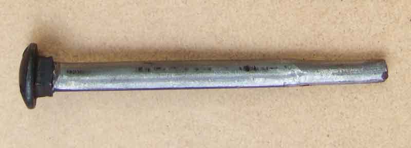
Flywheel locking pin cut down from a 10mm (shank) bolt. I put the threaded end in a drill chuck, then used that as a kind of lathe to 'turn down' 36mm from the head to 9.7mm, then a further 12mm to 7.4mm, then cut off after that. That was before I butchered it trying to get it into the wrong hole!
Note the bolts are screwed into the fixed and pivoting arms by different amounts so they engage the cut-outs in the sprocket equally.
The curious sump washer with the rubber insert (now known to be a 'Dowty' washer). Looking in Halfords for solid aluminium ones I noticed this type specified for Ford (yuk).

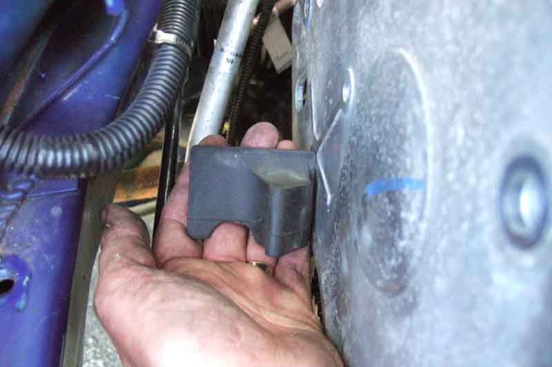
Orientation of the tension rubber cover. This is held beside the position it fits in the lower rear part of the front cover.
One of two unnecessary tools. Haynes calls for a tapered pin to help locate the sprocket over the hole to enable insertion of the bolt. This seems to be based on the two tapered pins used in the pukka MG Rover kit when both sprockets are removed and slid back on as an assembly with the belt. I couldn't see how that would help with the Haynes method, so made this pin which is actually eccentric rather than tapered, so that as the bolt was turned it would move the sprocket outwards and so locate it over its keyway. Not required, the bolt fitted right in, then turning it pulled the exhaust sprocket back into alignment and tightening the inlet bolt simply pulled it onto its keyway.
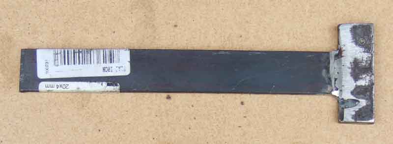
The other unnecessary 'flat bar tool' made from a few inches of offcut from a 1 metre length of 20mm x 4mm flat bar, with another 48mm length welded crosswise. In the event it wasn't needed, it kept slipping out of the shallow notches in the end of the sprocket. It might have been of more use if the crosswise piece were T-shaped to fit inside the sprocket as well as engage the slots.
Homemade degree-wheel. What more could anyone want for a one-off job?

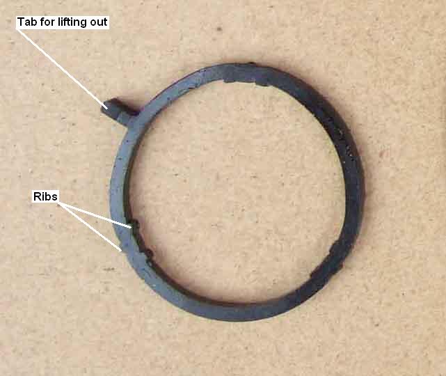
One of the three front inlet manifold sealing rings, showing the tab that can be lifted up by a finger nail to remove the old one, and the ribs that have to be compressed slightly with the back of a finger-nail to insert the new.