
Chrome Bumper to 1970 Chrome bumper 1972 model on and all V8s Rubber bumper to 1976 (not V8) Rubber bumper 1977-on Adding a relay
Hover over a wire to confirm the colour

Notes:
- North America used a separate switch and warning light, and white/black wires from fuse to switch and switch to screen, from 1968.
- There was a separate wire from the front to the back of the car for the HRW, and on at least one example this feeds the left-hand side of the screen instead of the right-hand side on later cars. Also being optional the earth wire route and connection could be anywhere.

Notes:
- Pull-switch with integral warning light used from 1973 in North America.
- In some diagrams the wire to the external warning light is shown as red with a brown stripe off the same terminal as the white/black to the screen.
- The 12v circuit from the switch has bullet connections where the main harness joins the rear harness in the engine compartment, by the right rear light cluster where white/black for the HRW goes up the C-pillar (together with purple for the load space light); and where the white/black connects to the wire coming out of the screen rubber by the right-hand hinge.
- The earth circuit uses a single black wire down from the bullet connector by the left-hand hinge, to the top mounting point for the left rear light cluster.

Notes:
- Green from the output of the switch to the relay is logically incorrect. This colour is normally used for fused ignition i.e. is live all the time with the ignition on which would operate the relay all the time. It also means that two different colours are on the same terminal which normally never happens - the other being red/brown to the warning light. Strictly speaking red/brown should have been used as the colour feeding the relay as well as the warning light.
- The 12v and earth connections are the same as for the 1971 and later, see Notes 3 and 4 here.

Notes:
- The switch was illuminated - (a) above - with the parking lights on and hence has additional red/white and earth wires.
- From some time in 1978 the HRW (GTs in RHD only by this time) was powered from a subdivision of the green circuit fed by a separate in-line fuse under the fusebox instead of the green from the fusebox. One of two connecting a white/brown to a green, it is the one with the thinner wires, the other one with thicker wires is for the cooling fan. See ignition schematics for more info.
- Clausager says that 1977 models up to December 77 had the heated rear window switch with built-in warning lamp - (b) above - even though there was space beside the switch for the warning lamp. From December 77 to the start of the 1980 model year there was a separate warning lamp (c), however 77 to 79 (I do not have a 1980) diagrams only show the separate warning lamp. When the fog-guard switch was added in 1980 the space for the HRW warning lamp was lost and a switch with internal tell-tale of unknown part number was provided again. The drawing of the switch above is a bit of a guess as it's not clear from users whether the 1980 switch does have both night-time and tell-tale illumination, as one person says his has the latter but not the former.
- Clausager also indicates that the HRW relay was only deleted in Dec 77 at chassis number 455131, but that would mean there were both ignition and HRW relays involved from the start of the 1977 model year in Jun 76 at chassis number 410351, which seems unlikely.
- As well as the 12v and earth connections listed in Notes 2 and 3 above, 1977 and later cars have the white/black output wire going via a bullet connection (left unused on roadsters) and multi-plug behind the dash where the main harness joins the dash harness.
Albert Ross show this wiring on the connector to his 1980 HRW switch, which is rather confusing. There seems to be a green (12v, correct), three white/blacks (there would only be one to the HRW, plus one to an external tell-tale which he doesn't have), and a red/white for night-time illumination which would normally go to one of the spades on the side of the switch, plus a black (earth for night-time illumination to a spade on the other side of the switch) which isn't shown:

His switch, showing multiple pins instead of just two pins which is how replacement switches for the MGB are shown:

As the original switch part number is unknown this 1977 and later Mini switch YUF101680 might be suitable, although it has a yellow lens on the rocker instead of probably a green, and the edges of the rocker look more rounded. It still has the two spades on the side for the red/white and black wires, but has only two pins on the back for green and white/black wires (which is all it needs ...): (Moss Europe)

But information from owners is confusing in that cars earlier than 1980 only have the night-time illumination, but a 1980 has the tell-tale but not night-time illumination! Whether that is because of a failed bulb, or a faulty connection somewhere, wasn't established. More info on internal bulbs here.


Hatch closed, just a small loop of wire visible

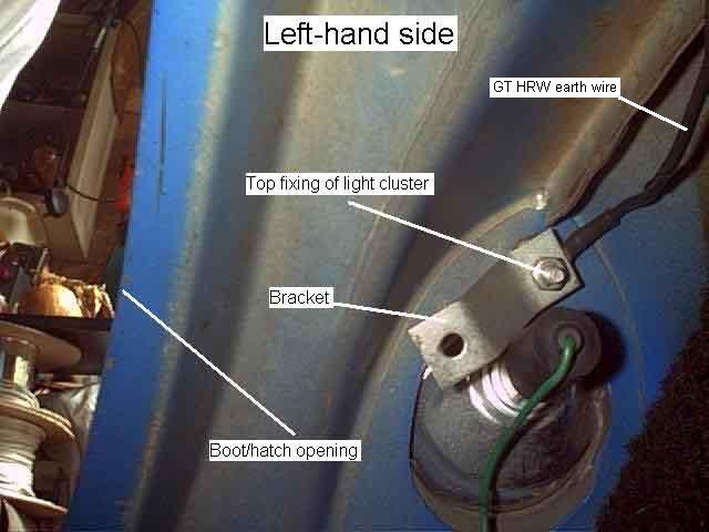
This is the earth wire which runs down the C-pillar to the top mounting stud of the rear light cluster. A similar wire runs down the other side to join with the rear harness by the light cluster. (The bracket is for the carpet piece that covers the back of the light cluster.)
The two 12v feeds going up the right-hand C-post for the HRW (white/black) and the load-space light (purple).

The soldered connection point on the surface-printed element, about mid-way down the side of the glass, with the connections and wiring covered by the rubber seal, but exposing a test-point.

Robert Kerr's car, glass removed, showing the two spades on the inner edge of the glass. I'd say extreme care needs to be taken if you need to disconnect/reconnect the wire attached to this connector, say when replacing the glass, to avoid the risk of detaching the connector from the screen.

Roy Marshall's replacement glass, showing the very inconvenient connection arrangements.

I suggest a right-angle wiring connector is the best way to get a half-way neat installation, however check the size of the spade on your glass first.
