
Updated August 2026: Two versions - the first has four white/brown wires at the front of the fusebox second fuse up and only one white on the ignition relay terminal 85:
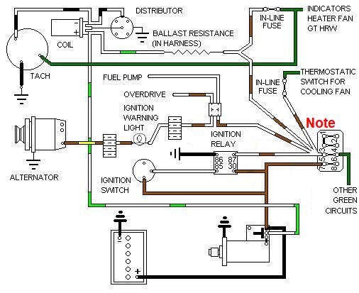
As with 1977 models if the ignition relay fails no ignition-powered circuits will work. The engine will start when you turn the key to crank but cut out again as soon as you release it, this is because the coil has an alternative power supply during cranking from the starter solenoid.
There are three separate white circuits: One from the ignition switch feeding the ignition relay, another in the rear harness feeding the fuel pump (which changes from white/brown at a bullet connector in the main harness), and the third feeding the ignition warning light (changing from white/brown at a multi-way plug behind the dash).
Note that the four white/brown wires are in two spade connectors at the fusebox, so in order for power to get to all four white/brown wires it has to come into the fusebox from the ignition relay on one spade and come out again on the other spade to feed the two wires in the other spade connector. This means that corrosion on the back of the fusebox (or on the spades) can affect some of the unfused ignition circuits as well some green circuits.
There are three separately fused green circuits: The original circuit fed from the 2nd fuse up in the 4-way block, and two others each fed by their own in-line fuse under the fusebox - one feeding the cooling fan switch, and the other feeding indicators, heater switch, tach, and GT heated rear window switch. Both these in-line fuses have white/brown (unfused) one side and green (fused) the other.
Multiple uses of the same colour and several changes from white/brown to white and back again does not help in diagnosing ignition problems.
At some time between 1978 and 1980 there was a subtle change moving the power feed to the ignition ballast and via one of the in-lines feeding the indicators, heater fan, GT HRW and tach from the output of the ignition relay to the input of that relay. This version has two wires on ignition relay terminal 85 and only three white/brown wires at the fusebox:
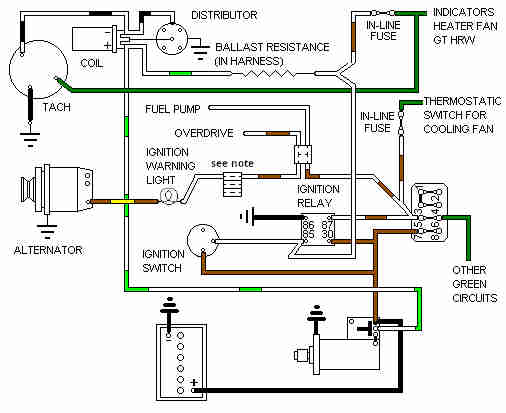
This arrangement means that the engine will start and run if the ignition relay has failed, and the indicators, heater fan, GT HRW and tach will work, but other fused ignition circuits (such as brake lights!) will not. There are three separate white circuits: One from the ignition switch feeding the ignition relay and ballast resistance for the coil (which then changes to white/brown for one of the inline ignition circuit fuses), another in the rear harness feeding the fuel pump (which changes from white/brown at a bullet connector in the main harness), and the third feeding the ignition warning light (changing from white/brown at a multi-way plug behind the dash).
There are two separate white/brown circuits: One teeing off the white from the ignition switch to the coil ballast for the indicators, heater fan switch, tach, and GT HRW. The other is from the relay contact feeding the fusebox, cooling fan in-line fuse, overdrive, fuel pump and ignition warning light.
Note that the supply from the ignition relay is the single wire at the fusebox, and the wires to the fuel pump, overdrive etc. and to the cooling fan fuse share a single spade connector. This means that power has to go into the fusebox on one spade and come out on the other spade to feed the paired white/browns, so corrosion inside the fusebox can affect all those circuits as well as the green circuits fed by the fusebox.
There are three separately fused green circuits: The original circuit fed from the 2nd fuse up in the 4-way block, and two others each fed by their own in-line fuse under the fusebox - one feeding the cooling fan switch, and the other feeding indicators, heater switch, tach, and GT heated rear window switch. Both these in-line fuses have white/brown (unfused) one side and green (fused) the other.
Multiple uses of the same colour and several changes from white/brown to white and back again does not help in diagnosing ignition problems.
There is also the in-line fuse for the hazard flashers under the fusebox with brown wires both sides.
This clearly shows the two white/brown to green ignition circuit in-line fuses nearest the camera and the brown to brown hazard fuse further away. It also clearly shows that the way the wires have been routed and the orientation of the ignition circuit in-line fuses that it's possible to erroneously connect white/brown to white/brown and green to green, which was how a new harness came to me from the supplier and caused some head-scratching when I first powered it up!

The schematics show the original rectangular Lucas relays with W1, W2, C1 and C2 terminal numbering, but in practice cylindrical relays (and then cube-type SRB 520) with ISO numbering were fitted. The relationship is as follows:
| Wire colour | Original numbering | ISO numbering |
| White from ignition switch | W1 | 85 |
| Black earth | W2 | 86 |
| Brown 12v supply | C2 | 30 |
| White/brown to ignition powered circuits | C1 | 87 |
Information on the ballast resistance can be found here.