
November 2011: In recent weeks Blake Thornton and Michael Field have contacted me about coil-boost starting systems - Blake with a problem with the factory starter relay on a Jaguar, and Michael with an after-market geared starter that doesn't have the coil boost contact that his V8 should have, and for various reasons was causing starting problems.
Many of these after-market starters don't have the coil-boost contact on the solenoid as fitted originally to rubber-bumper cars and all V8s (the one I had for a while didn't). Whilst starting should be OK under most normal conditions, under marginal conditions it can make the difference between starting and not starting, and it's possible to reprovide the coil boost in a number of ways.
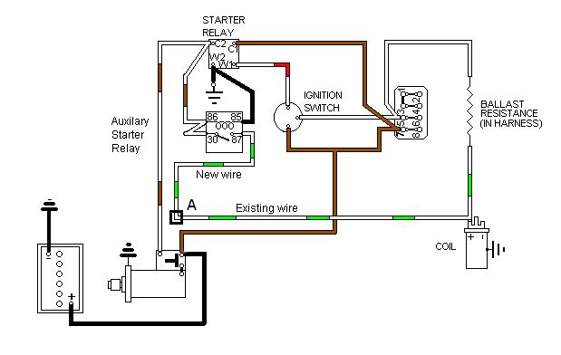
The easiest way is to replace the existing starter relay with one with two normally-open contacts. Only one additional wire is required up from the existing white/light-green by the solenoid to the relay, with a male spade at the lower end to connect to the female connector on the end of the harness wire at 'A'. However these are less readily available and you must ensure the contacts operate as described before connecting and using the relay. Three types are available:
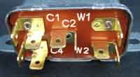 A Lucas SRB301 (22RA 33336 or 33356) in a metal can that is in keeping as a replacement for the original 6RA type. They were used as standard equipment on some Jaguars and Triumphs for exactly this purpose and are in fact called starter relays. These have a C4 terminal in addition to the W1, W2, C1 and C2 terminals. With the relay released C1, C2 and C4 should all be isolated from one other. When the relay is operated all three contacts should be connected together. Nothing else will do. The white/red wire goes to W1, black to W2, brown to C2, white/brown to C1, and white/light-green (white/light-blue for V8s) to C4.
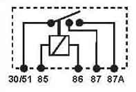 They are also available in cylindrical form (albeit blue) as SRB400 (26RA 33231), with an 87a terminal as well as an 87. However you have to be careful with this as 87a is also used for the normally-closed contact on other relay types, which must not be used in this application, so you have to look at the schematic on the relay as well as the terminal numbering. With the relay released 30/51, 87 and 87a should all be isolated from one other. When the relay is operated all three contacts should be connected together. Again nothing else will do. White/red goes to 85, black to 86, brown to 30/51, white/brown to 87, and white/light-green to 87a.
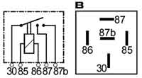 Finally there is a Bosch cube-type SRB521 with 30, 87 and 87b contact terminals. With the relay released 30, 87 and 87b should all be isolated from one other. When the relay is operated all three contacts should be connected together. Again nothing else will do. White/red goes to 85, black to 86, brown to 30, white/brown to 87, and white/light-green (white/light-blue for V8s) to 87b.
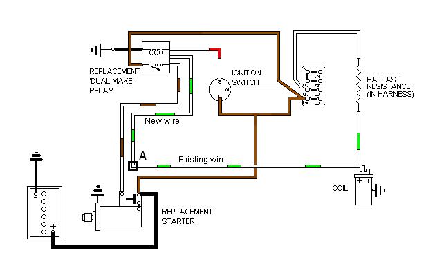
Another option is to provide an additional auxiliary starter relay which operates in tandem with the original relay. As well as tapping onto the existing white/brown and black wires on the existing relay using piggy-back connectors, a new white/light-green (4-cylinder cars, white/light-blue on V8) is run down to the solenoid with a male spade to connect to the existing female connector on the harness wire at 'A'. A readily available accessories relay from all the usual suspects will do this as shown here:
Finally you can get quite exotic and use a 10 amp diode between the solenoid operate wire and the coil boost wire down by the solenoid, but really need to know what you are doing with semiconductor diodes for this option. Also diodes, like all semi-conductors, exhibit a forward volt-drop when carrying current so do not provide as much boost as a relay. Basically you want current to flow from the solenoid operate wire to the coil boost wire, but not the other way. For that, typically the marked end of an axial diode is the positive end and would be connected to the coil boost wire, the negative end to the solenoid wire, as shown here:
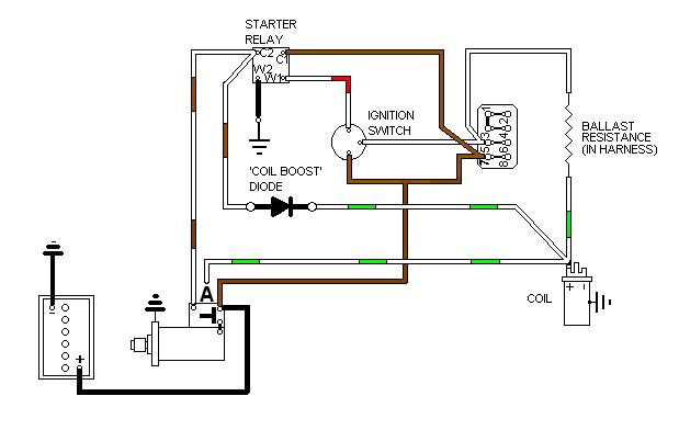
Whilst physically it would be easiest to install the diode at the solenoid (Moss US supply an adapter for this purpose, see 'Instructions and resources') environmentally conditions aren't very good for electric stuff down there so it would be better to install it higher up by the starter relay or coil. The original wire to the solenoid boost contact at 'A' should be insulated and taped back out of the way to prevent it shorting to anything.
Information on the ballast resistance can be found here.
Note that the wire from the starter relay to the solenoid operate terminal is white/red on later cars, but a heavier gauge than normal wiring.
As to why the coil can't simply be linked to the solenoid contact on the starter relay, consider the circuit below which has just such a link shown in red:
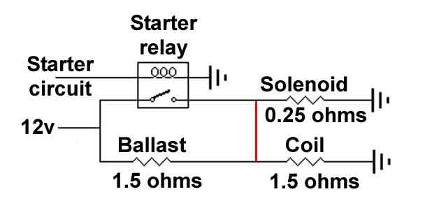
- This puts the solenoid in parallel with the ignition coil. The solenoid winding has a resistance of 0.25 ohms and the ignition coil is 1.5 ohms, which gives a combined resistance of 0.21 ohms.
- Those two in parallel are in series with the ballast resistance which gives an overall resistance of 1.71 ohms (1.5 ohms plus 0.21 ohms) and creates a network.
- The network has 12v applied to it, and its overall resistance of 1.71 ohms causes 7.02 amps to flow - I = V / R.
- That 7.02 amps is flowing through the 1.5 ohm ballast resistance and results in 10.5 volts being developed across it - V = I * R.
- With 10.5 volts across the ballast resistance that only leaves 1.5 volts for the coil and the solenoid.
1.5 volts across the solenoid is largely irrelevant, but the coil is expecting four times that so the result will be a very weak HT and probably no spark at all. The engine will start normally as the starter relay connects a full 12v to the solenoid and to the coil, but when you release the key the engine will probably cut out.