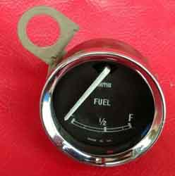
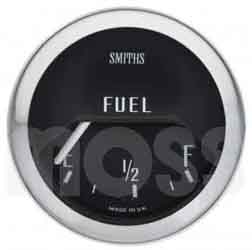
Smiths, early magnetic system, externally lit, FG2530/70 BHA4381:
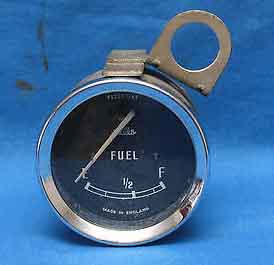
Smiths, Mk1 thermal, externally lit, BF2300/02 BHA4470:
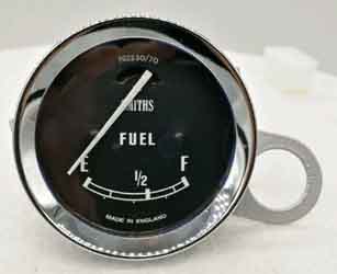
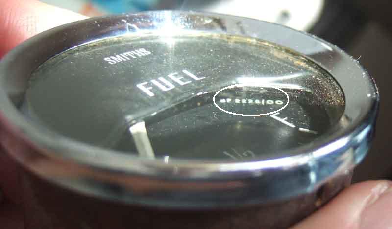
Smiths, Mk2 thermal prior to 1977, shrouded pointer, internally lit, BF2223/00 and BF2226/00, BHA4685 and BHA4736: (Moss Europe)
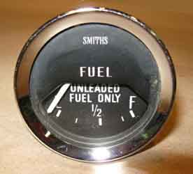
Smiths, thermal North America unleaded 1975-76, BF2226/02 BHA5342:
Smiths, thermal, RHD, 1977-on, BF2239/00 AAU3032:
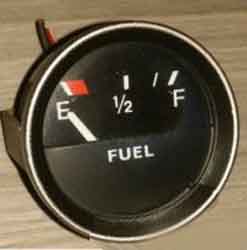
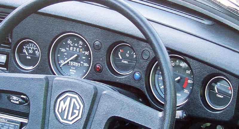
Unfortunately this gauge is very difficult to get at being immediately above the steering column.
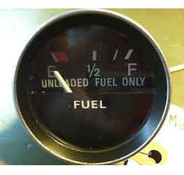
Smiths, thermal, unleaded, LHD, 1977-on, BF2239/01 AAU3031:
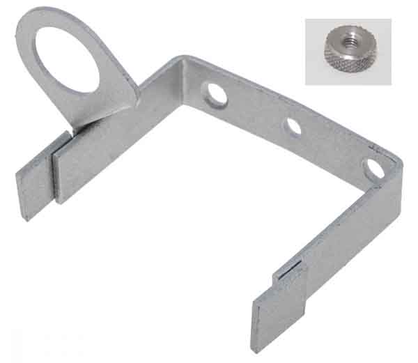
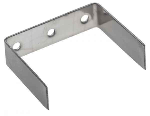
Internally illuminated fuel, dual and round temp and oil pressure gauge fixing strap AJH5187 uses the same thumb nut and spring washer as above: (Moss Europe)
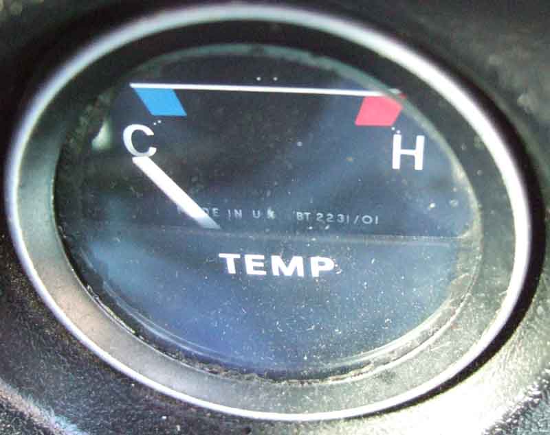
Later gauges from September 76 on with the upwards pointer have the identification number behind the lower part of the dial, as in this example of a temp gauge:
As far as I have been able to ascertain these are the various fuel gauges and senders used over the years for each market:
| Part No. | Reference No. | Chassis numbers | Dates | Notes | Sender | Notes | ||
| BHA4214E | FG2530/63 | 101 | 47712- 48767 | May 62 | Oct 64 | Jaeger, magnetic, externally lit | BHA4292 | Screws to tank |
| BHA4381E | FG2530/70 | 47712- 48767 | 56742 | Oct 64 | Mar 65 | Smiths, thermal, exposed pointer, externally lit | BHA4471E | Screws to tank |
| BHA4470 | BF2300/02 | 56743 | 138400 | Mar 65 | Nov 67 | Smiths, thermal, internally lit | ARA966/ AHU1027 | Locking-ring to tank |
| BHA4736 | BF2223/00 | 138401 | 153877 | Nov 67 | Aug 68 | Shrouded pointer, Canada | ARA966/ AHU1027 | Locking-ring to tank |
| BHA4736 | BF2223/00 BF2226/00 | 138401 | 415000 | Nov 67 | Sep 76 | UK | ARA966/ AHU1027 | Locking-ring to tank |
| BHA4865 | Note 1 | 138401 | 258000 | Nov 67 | Aug 71 | USA, Sweden, Germany | ARA966/ AHU1027 | Locking-ring to tank |
| BHA4865 | Note 1 | 153878 | 187840 | Aug 68 | Sep 69 | Canada | ARA966/ AHU1027 | Locking-ring to tank |
| BHA4736 | BF2223/00 BF2226/00 | 187841 | 415000 | Sep 69 | Sep 76 | Canada | ARA966/ AHU1027 | Locking-ring to tank |
| BHA4736 | BF2223/00 BF2226/00 | 258001 | 382134 | Aug 71 | Jun 75 | North America | ARA966/ AHU1027 | Locking-ring to tank |
| BHA4736 | BF2223/00 BF2226/00 | 258001 | 415000 | Aug 71 | Sep 76 | Sweden, Germany | ARA966/ AHU1027 | Locking-ring to tank |
| BHA4736 | BF2223/00 BF2226/00 | 101 | 2903 | Dec 72 | Jul 76 | All V8 | ARA966/ AHU1027 | Locking-ring to tank |
| BHA4736 | BF2223/00 BF2226/00 | 258001 | 386267 | Jun 75 | Sep 75 | North America except California | ARA966/ AHU1027 | Locking-ring to tank |
| BHA5432 | Note 2 | 382135 | 415000 | Jun 75 | Sep 76 | California, 'Unleaded Fuel Only' | ARA966/ AHU1027 | Locking-ring to tank |
| BHA5432 | Note 2 | 386601 | 415000 | Sep 75 | Sep 76 | Rest of USA, 'Unleaded Fuel Only' | ARA966/ AHU1027 | Locking-ring to tank |
| AAU3032 | BF2239/00 | 415001 | 523002 | Sep 76 | On | UK | 11H5062/ ADU3218 | Integral outlet pipe Note 3 |
| AAU3032 | BF2239/00 | 415001 | 443980 | Sep 76 | Sep 77 | Japan | 11H5062/ ADU3218 | Integral outlet pipe Note 3 |
| AAU3031 | BF2239/01 | 415001 | 523002 | Sep 76 | On | Rest Of World (not Japan), 'Unleaded Fuel Only' | 11H5062/ ADU3218 | Integral outlet pipe |
| AAU3031 | BF2239/01 | 443981 | 523002 | Sep 77 | On | Japan, 'Unleaded Fuel Only' | 11H5062/ ADU3218 | Integral outlet pipe |
Updated July 2009: However the voltage stabiliser changed at the same time as the gauges, and it seems that with the wrong mix of gauge and stabiliser the fuel gauge at least gives incorrect readings. Mk1 cars used part number 27H 7819, Mk2 cars used BHA 4602.
Note 2: Clausager indicates LHD cars got different gauges with the new plastic dash of September 76, and the part numbers in the Catalogue do change. However he has two photographs of the North American plastic dash - one with chrome bezelled instruments and a 120mph speedo, and the other with plastic bezelled instruments and an 85mph speedo, the 85 mph speedo only arriving with the 1980 models in June 79. If his photos are 'correct' then all the LHD instruments must have changed again after the start of the 77 model year, possibly at the start of the 80 model year when the speedo changed, but the Parts Catalogue doesn't reflect this (by then it doesn't show the late change to the 85mph speedo either). One source of an early Californian 'Unleaded Fuel Only' gauge indicates it has the same reference number as the later gauges, so again the reason for the part number change is not known. Because the sender changed in September 76 it's possible it's characteristics changed, which may well need a different gauge from the earlier sender, but that would have been the case for the 77 model year chrome bezel gauges as well as the 80 model year plastic bezel! All very confusing.
Note 3: GTs got the sender with integral outlet from chassis number 412301, the roadster from 415001, however both were August/September 1976.
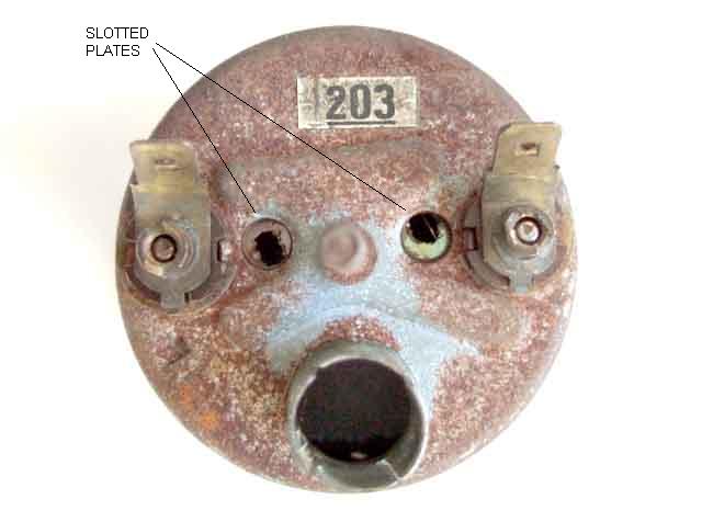
Rear of the gauge (right way up) showing the slotted plates through the holes in the case. This is a old, spare gauge hence the scabby appearance. I used this when first testing my ideas for calibration, before I realised how easily damaged the slots were. Note that it is not required to open up the gauge for calibration, it is done from the back:
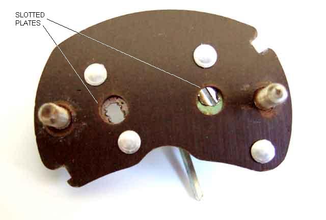
Rear of the mechanism out of the gauge, again showing the slots:
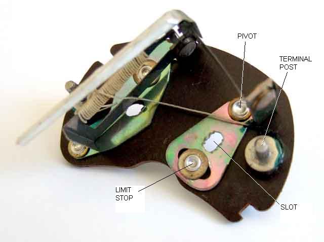
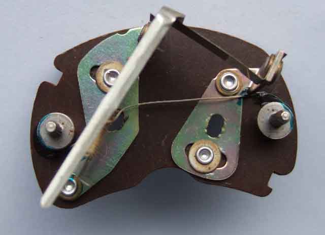
Front of the mechanism showing the 'F' slotted plate with the 'screwdriver' slot in the middle, the pivot at the top, and the limit stops at the bottom. As you can see adjustment is almost more of a case of pulling the slot towards the terminal post, or pushing it away, rather than turning it on its own axis as one does a screw:
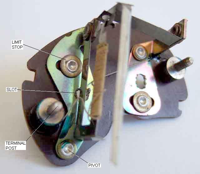
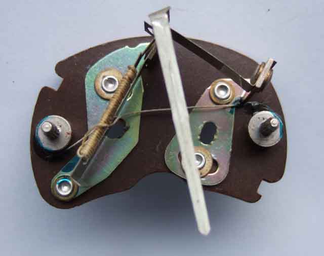
Front of the mechanism showing the 'E' slotted plate with the 'screwdriver' slot in the middle, the pivot at the bottom, and the limit stops at the top. Note the heater winding is wound on just one half of the 'U' that is the bimetal strip. This is the ambient temperature compensation mechanism. Because one end of the 'U' is attached to the base and the other to the pointer, any ambient temperature changes cause the 'U' to bend equally in both halves of the 'U', so effectively the two ends stay in the same position relative to each other, and the pointer does not move. But when a current is applied to the heating coil, only one half of the 'U' is heated, the ends of the 'U' move relative to each other, and this causes the pointer to move. I only discovered this when heating the whole of the gauge to see how much ambient temperature changes affected it as I was of the opinion that the temperature compensation was done in the stabiliser. I was initially surprised to see no movement of the pointer, but then realised the significance of the 'U' shape of the bi-metal strip. Confirmed by laying a pencil soldering iron across first the unwound section, then the wound section, on the unwound section it caused the pointer to move backwards, whereas on the wound section it caused the pointer to move forwards as one would expect:
Showing the E plate fully adjusted to the left:
Showing the E plate fully adjusted to the right. Note the gauge is not powered, and just goes to show how much pointer movement is affected by a small movement of these adjustment plates:
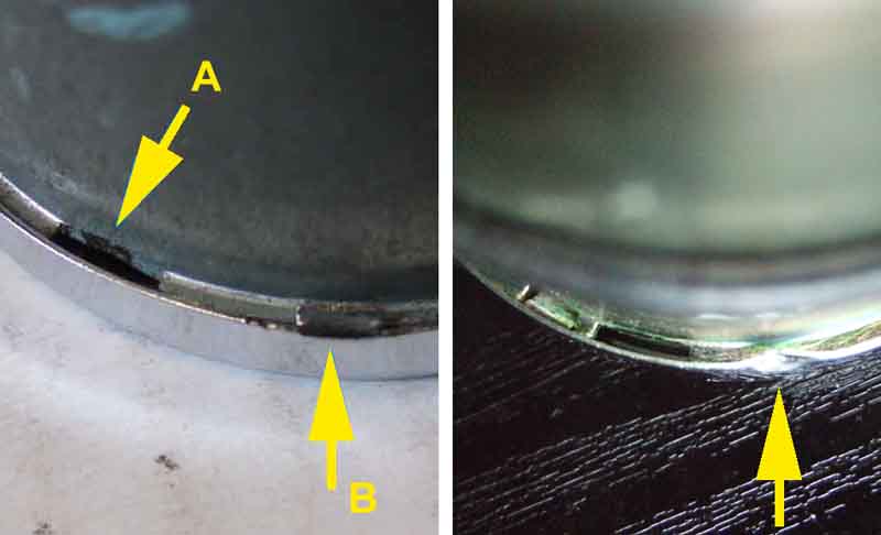
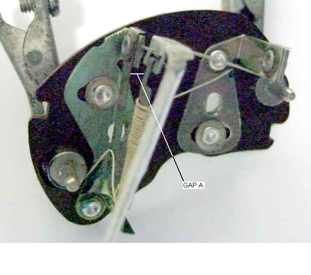
Gauge unpowered, showing the 'cold' gap (A) between the ends of the bi-metal strip:
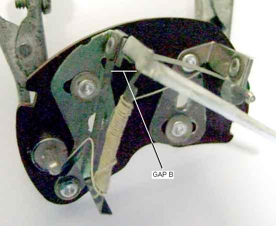
Gauge fully powered, showing the larger 'hot' gap (B) between the ends of the bi-metal strip. Note how the relatively small increase in gap causes full-scale pointer movement:
Unfortunately the 77 and later fuel gauge being above the steering column is nowhere near as easy to access, try removing the tach first: (Clausager)
Removing the bezel and glass - there should be three tabs on the bezel (A) folded over a flange on the case. The bezel needs to be twisted round until the tabs line up with cut-outs in the flange (B). However there is a rubber gasket which can glue things together, in which case the tabs may have to be levered back a bit with a screwdriver and the rest of the bezel eased away from the case flange bit by bit until it comes free. There should also be a square-section rubber O-ring on the outside of the case (not shown) to buffer the instrument against the dash panel: