
Energy-absorbing Steering Column
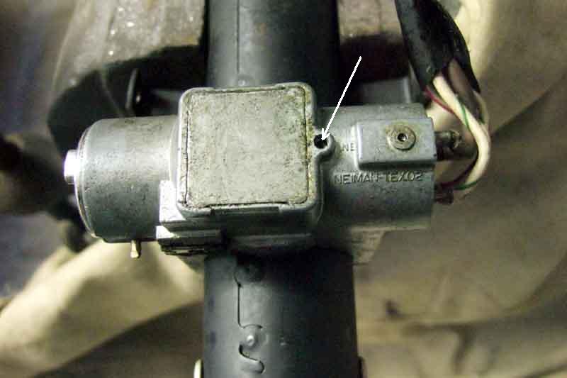
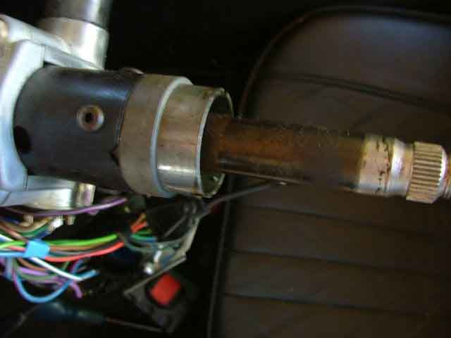
Location of ignition switch securing screw (arrowed)
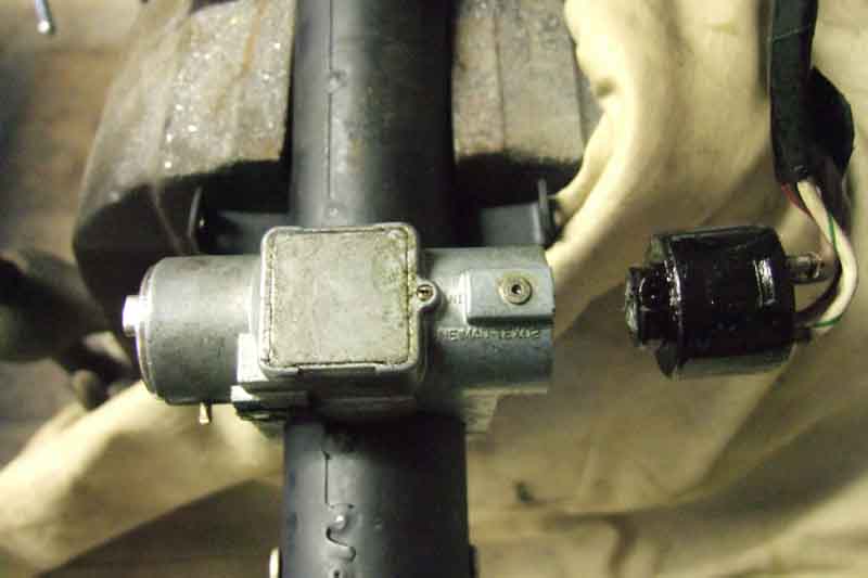
Screw slackened and switch removed
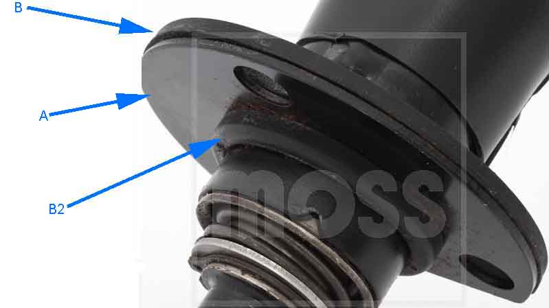
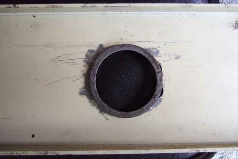
The loose plate at the bottom of the column, shown as part of the assembly in parts lists. The rubber seal is more or less the same size and shape but is separately quoted. Other people have a rubber sleeve that fits over the end of the column outer, inside the flange.
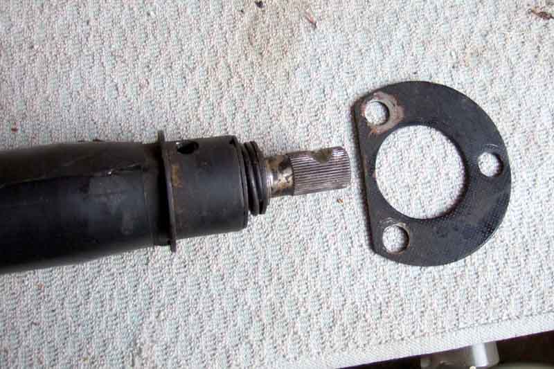
Moss Europe showing the plate (A) below the seal (B), which would mean the bolts tightening onto the rubber seal. It should be the other way round, to sandwich the seal between the plate and the toe-board. B2 is the portion of the seal that protrudes through the plate. Moss show the seal and plate separately here as item 33 (seal: CB AHA8270, RB BHH1856RBR (NCA) and plate BHH1856BKT)
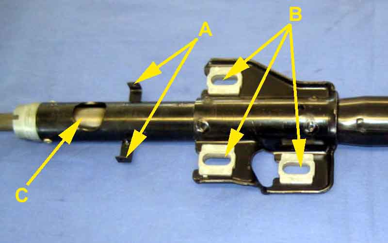
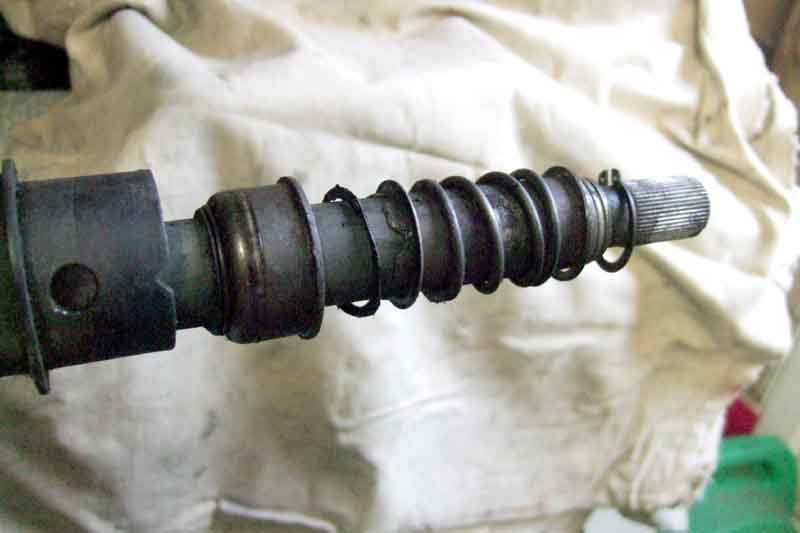
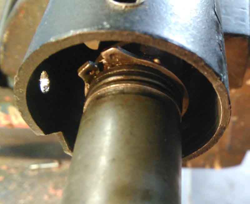
The lower bush, plastic 'washer', spring, steel washer, and circlip that secure the bottom half of the shaft into the column, the sheared 'pins' having allowed the lower part of the shaft to be pushed out of the column.
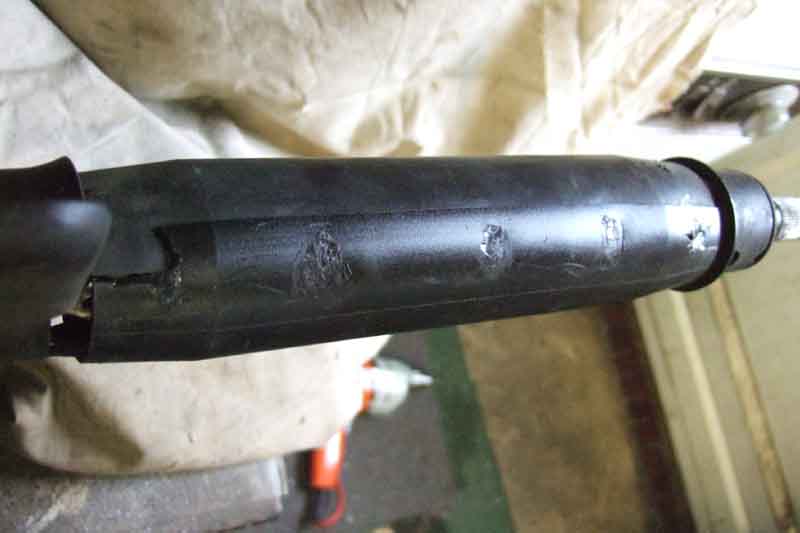
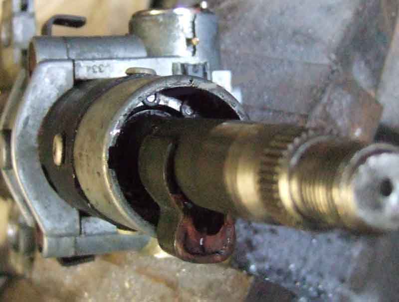
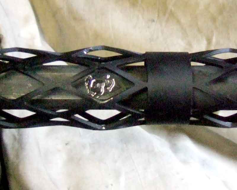
The plastic sleeve over the collapsible 'mesh' part of the column.
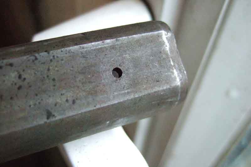
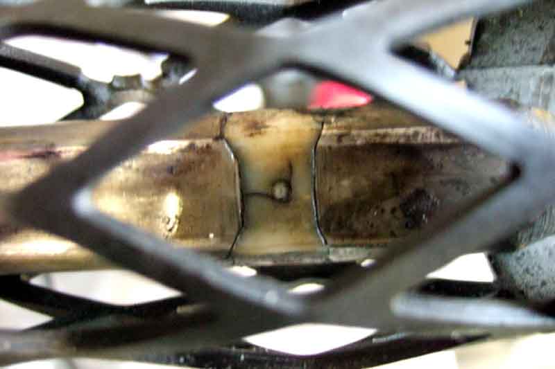
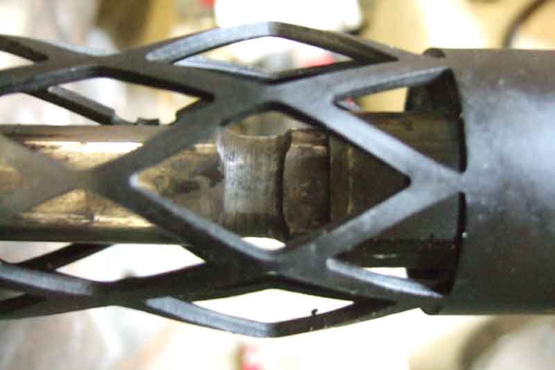
Stubs of plastic shear 'pin' remaining in the holes of the outer/lower part of the shaft ...
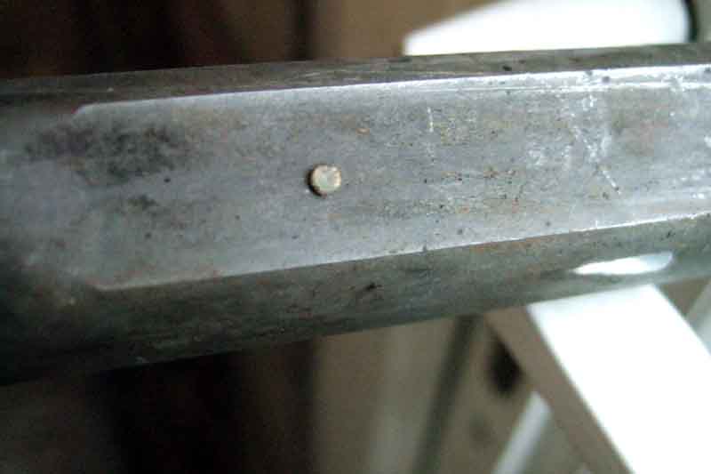
... removed
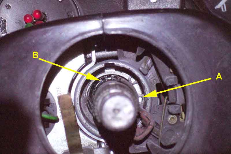
Upper bearing: Inner circlip (A) retaining my bearing in the housing (BHH1596), and outer circlip (B) retaining the shaft in the bearing. Although removing A allowed the shaft and bearing to move up and down inside the housing I still couldn't withdraw the upper shaft. From John's description this was possibly because the bearing was catching on the pop-rivets.
The (apparently superfluous) circlip behind John's bearing on the new, earlier (BHH1596) column. The circlip on his later (BHH1856) was sitting in front of the bearing (as is mine on an earlier column). As far as he could see the slots are the same on both. John says there is a shoulder on the shaft which should stop the bearing going down too far on the shaft, or the shaft being pulled up through the bearing. So with the bearing sandwiched between the two shoulders and the two circlips, there should be no possibility of the shaft moving relative to the outer, and hence no chance of putting stress on the shear pins. (John Bilham)
The earlier column BHH1596 with the bearing housing having the same OD for all its exposed length, the separate column switches clamp onto this.
The later column BHH1856 with the reduced diameter section for the later one-piece switch assembly to slot onto. (John Bilham)
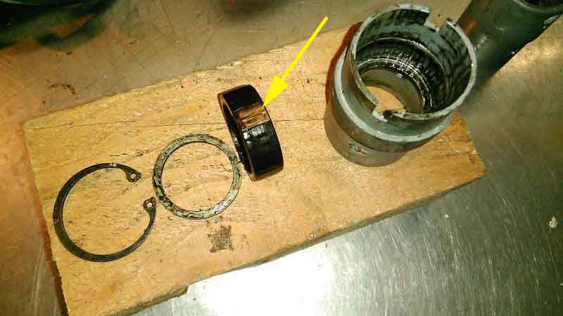
John's dismantled housing: A shoulder inside the housing positions the bearing, then a shim, and finally the large circlip to secure the bearing to the housing. The bearing is interesting - it is rubber-coated, except for a small section which is copper (arrowed). Speculation is that is to provide an earth from the column outer (bolted to the body) to the upper part of the shaft, as the injected plastic shear may prevent an adequate electrical connection to the lower shaft (which should have an earth via the UJ, rack and crossmember and chassis rails). However this is the 77 and later column, with the horn button on a stalk which sends 12v to the horns, so a column earth is not required. It is required on the earlier rubber bumper column, but I and others have had problems getting a satisfactory earth to the horn button, so if there it doesn't work very well. (John Bilham)
Remains of the injection moulded plastic in the upper half of the shaft, I gave up on removing the upper bearing so worked through the mesh:
The 'waisted' section the injection moulding sits in:
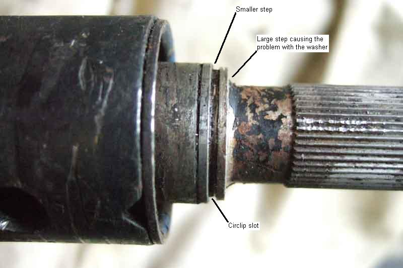
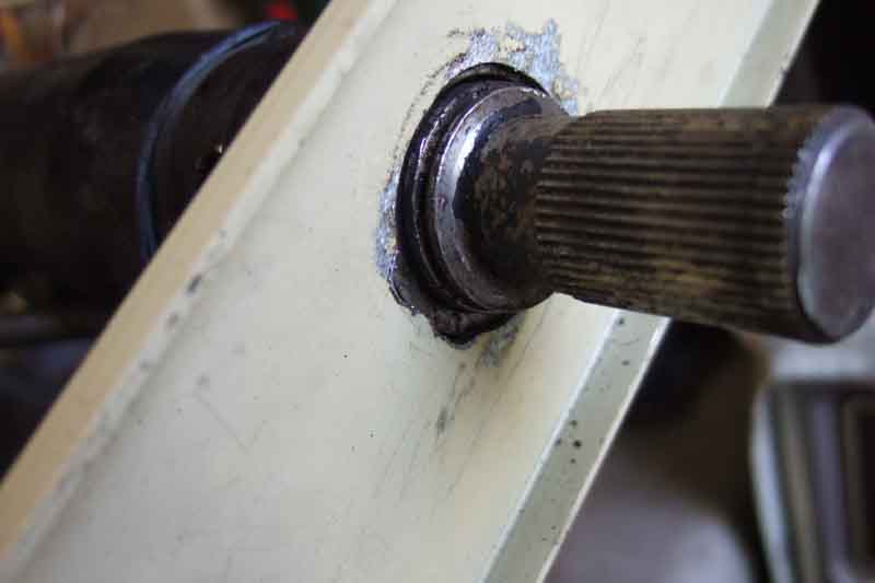
Reassembly: The 'steps' in the shaft, the washer kept getting caught on the bigger one when I tried compressing the spring.
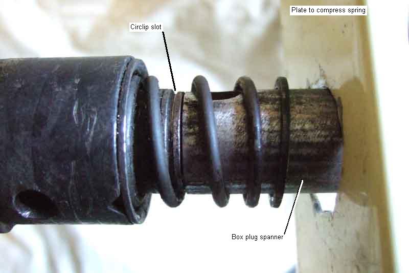
Box plug spanner neatly fits over the narrowest part of the shaft, and inside the spring and washer, so nullifying the effect of the first, large, step. The smaller step wasn't a problem.
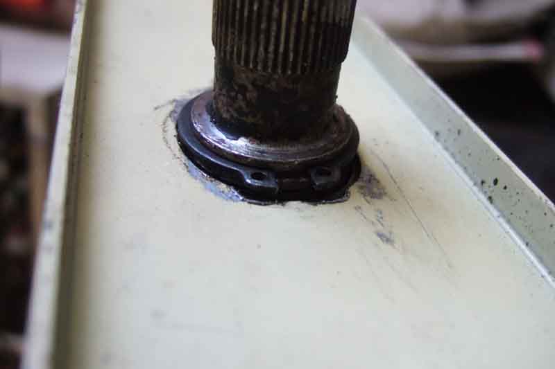
'Keyhole' in plate cut to be slightly bigger than the circlip ...
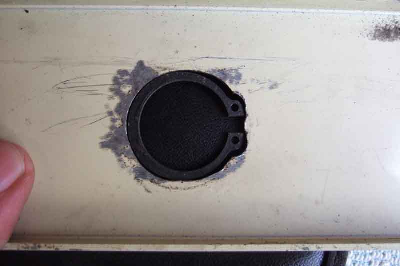
... but smaller than the washer it has to press against.
String wound up by a tommy-bar (from the same box plug spanner!) to pull on the plate and compress the spring ...
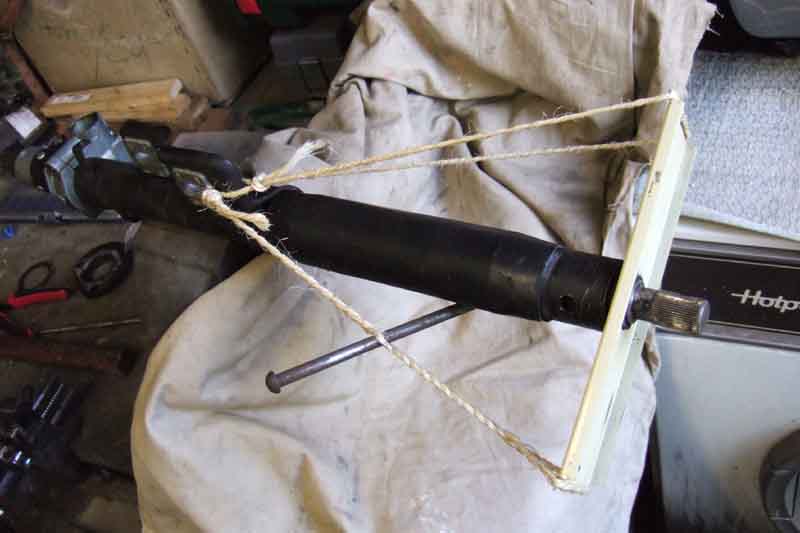
... the box plug spanner can then be removed ...
... and the circlip fitted!
For reinstallation and aligning see here.