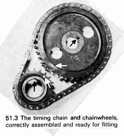
Leyland Workshop Manual image, white arrows showing the positions of the keyways and black arrows showing the position of the dimples.
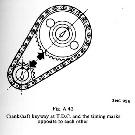
To install the distributor drive dog correctly, using the instructions contained within the manuals which state that No.1 piston must be at TDC on its compression stroke, the crank must be turned one full turn i.e. 360 degrees. This puts the camshaft keyway adjacent to the crank gear, and the cam gear dimple at top-right. Then follow the instructions for inserting the drive gear.
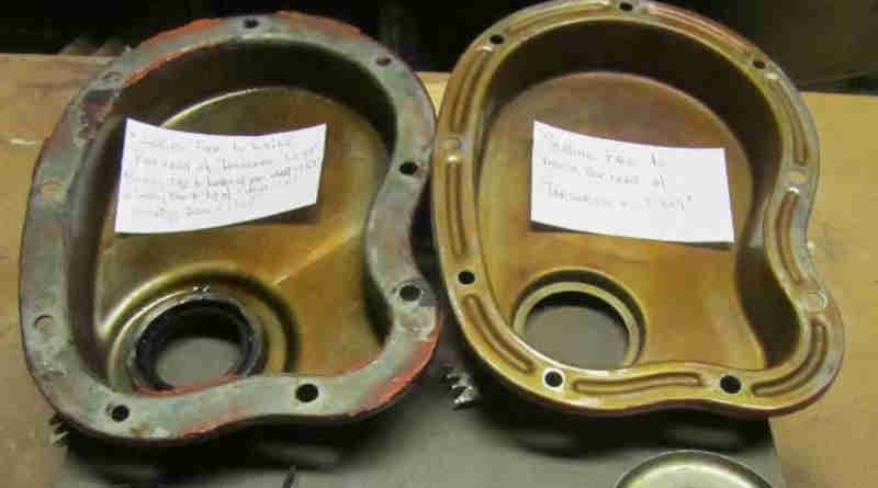
Timing covers - flat flange on MGA (left), ribbed on (most if not all) MGB: MGAGuru
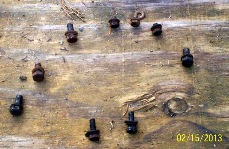
Timing cover bolts:
It's fairly self-explanatory where the bolts go. It's obvious the four 5/16" bolts will only go in the appropriate holes, the three shorter 1/4" bolts go at the top into the engine front plate where there is no block behind it, and the two longer ones go at the bottom through the front plate into the block. Torque to 6 ft lb for 1/4" and 14 ft lb for 5/16".
(Photo: Chris Wilson)