


Connections
Caps
Plug Leads
Firing Order
Points
Earth Wire
Condensers
Rotors
Centrifugal Advance
Vacuum Advance
O-rings
Installation
Drive Gear
Clamp Plate
Adjustments
Curves
 Originally all MGBs were fitted with a points-type Lucas 25D4 distributor rotating anti-clockwise. The main difference in this to other types fitted over the years is the vernier adjustment that allows for fine-tuning of timing. Originally necessary in the days when fuel octane might have been a bit variable between suppliers, since the advent of unleaded it has come back into its own. If you have your timing set to take advantage of the higher 97-99 octanes and get better performance and economy, when touring in the wilds (even in the UK) you may find you can only get 95 octane and your engine will start pinking badly. The vernier adjustment allows you to retard the timing by a couple of degrees to stop the pinking, then put it back again when you can get the higher octane. However not so convenient for changing the dwell, one would normally have to keep stopping the engine, removing the cap, tweaking the points gap, refitting the cap and restarting the engine, but there is way of simplifying the process.
 From November 1974 the points-type 45D4 distributor was used on all cars to the end of production on non-North American-spec cars and also rotates anti-clockwise. The vernier adjustment was deleted, but the points installation was improved by having a tag on the points wire that pushed into a clip on the points spring, instead of the fiddly insulating washers and nut of the 25D4. Clausager says that some cars in the 1978-80 period used a Ducellier distributor, but I've never heard of one of these being found in the wild. With these distributors to alter the timing it is a case of slackening the clamp plate bolts - or the clamp bolt itself if you are at the limit of the slots in the clamp plate - and twisting the body of the distributor plate, anti-clockwise to retard, clockwise to advance. Again to adjust the dwell one would normally have to keep stopping the engine, removing the cap, tweaking the points gap, refitting the cap and restarting the engine, but there is way of simplifying the process.
For the 1975 model year onwards North American-spec cars had electronic ignition, as they were required to go for 50k without any engine adjustments, and points needed replacement every 10-12k. Initially the 45DE4 'Opus' system, it proved unreliable and many were replaced under warranty. A much better alternative which replaced the 45DE4 was the 45DM4, which proved to be very reliable, the system being used on many other makes and marques. More on these types can be found here.
 The V8 used the 35D8 points distributor throughout, which rotates clockwise . The feature of note with this distributor is the ability to change the points gap and hence dwell with the engine running by turning a hex shaft that protrudes from the distributor body. Other than that timing is altered by twisting the distributor body - this time clockwise to retard and anti-clockwise to advance. However as the factory V8s are low-compression and should be set up for and run on 95 octane, one normally wouldn't need to alter it for reasons of petrol.
Distributor Connections June 2016
Points wire: But first the points wire. On 25D4 distributors the harness wire connects to a spade terminal on the side of the distributor. Internally that then has a very flexible cloth-covered wire connected to the points spring and hence the moving contact. On 45D4 distributors there is black plastic insulated wire coming out of the distributor that terminates in a male spade, which connects to the female spade on the harness wire, i.e. an in-line connection. Internally this wire goes to a tag which goes into a clip on the end of the points spring, and from there to the condenser. Despite being black plastic insulated this is a much more flexible wire than wiring used elsewhere on the car. The reason for these very flexible wires on both the 25D4 and 45D4 is that when driving the points plate is continually being twisted back and fore by the vacuum advance module, as the accelerator pedal moves up and down, to alter the timing, which continually flexes the wires. These wires are designed to cope with this twisting and flexing, but eventually they can fracture, which will give intermittent ignition i.e. cutting-out, and probably backfiring in the exhaust. Fortunately on cars with the electronic tachometer (i.e. not the early mechanical rev-counter) these faults will almost certainly cause the tachometer needle to be jumping about, or have dropped to zero when the ignition is still switched on and the momentum of the car is still spinning the engine. But note breaks anywhere in the ignition circuit - not just these wires inside the distributor, will result in the same symptoms. The fractures will almost certainly be inside the insulation and so not immediately visible to the naked eye. On the 25D4 the wire and spade terminal (37H2981) will need to be replaced, but on the 45D4 it is part of the condenser wire so a new condenser will be required.
August 23:
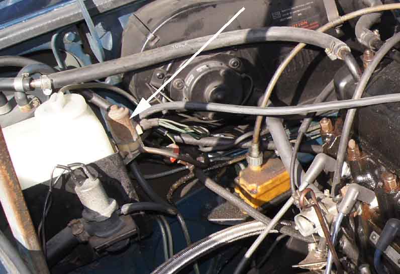
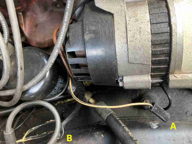 Someone on the MGOC forum had what he called a yellow/black wire coming out of the harness with the alternator wires but not connected to anything and wondered where it should go. A couple of others said the same, but it turned out that they all had late model cars with electronic ignition. It's actually the original (but discoloured) white/black wire that went from the coil to the distributor, which was puzzling as on my 73 it comes out with the coil wires and not the alternator wires. However I'm pretty sure Bee had it wrapped round the steering column at one point and someone else said the same thing. I wondered if the factory had re-routed it round the back of the oil filter to prevent that, and sure enough that's exactly what the 1978 Leyland Workshop Manual shows in its harness (yes harness, not 'loom') layout drawings for both RHD and LHD.
Points Types Added January 2008
If replacing the condenser or points screw at any time make sure it's not too long or it can foul the weights and cause a misfire.
Despite there only being two types of points distributors for the 4-cylinder MGB there are at least four points types - two for each.
 25D4 use either a fiddly one-part (GCS101) or an even fiddlier 2-part (GCS107). These may be interchangeable, but I can't guarantee it as I haven't tried. On both types there a number of parts that go to make up the electrical connection and it is essential that these are assembled in the correct order (click thumbnail) or you can end up with very weak ignition because the condenser is not connected, or no ignition because the points are shorted out. Lucas variants of the GCS101 have a red cam follower, and the Lucas GCS107 a black. Colour may vary for other manufacturers, I have seen white. Quality may also vary with other manufacturers! Both position the cam-follower pivot over a pin on the points plate for location, and have an adjuster notch at the connection end. The 25D distributor has a spade connector on the side of the body to which the coil wire attaches. Inside, between this spade and the points, there is a very flexible cloth-insulated wire with very fine conductors inside, to cope with the continual bending which comes from the twisting of the points plate under different amounts of vacuum advance. There is another of these wires between the points plate and the distributor body, which provides the earth path for ignition current. The tags are crimped round the cloth insulation for physical strength as well as avoiding sharp bends at the edge of the tags as the wire flexes. If either of these cloth-insulated wires fray they can give intermittent ignition, usually when you alter the throttle and hence the vacuum advance, and sometimes ignition fails altogether. They do not seem to be available separately (although look to be new in rebuilt distributors), it has been suggested that 'solder wick' aka 'desoldering braid' may make a suitable alternative, but I'd advise crimping connectors to these and not soldering, for obvious reasons (I hope!). The condenser is a separate component.
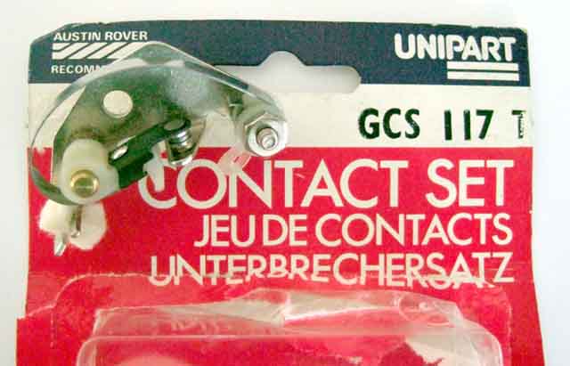
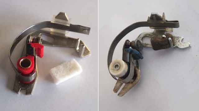 45D4 have 'quick-fit' points which as the name implies are quick and easy to connect (although just as fiddly to fit to the points plate and adjust for correct gap) and there is less chance of getting the connections, at least, wrong. The points include a felt wiping pad which rubs on the cam, the cam must be greased not the pad, and not oiled.
Additionally for the 45D4 there are 'non-sliding' (GCS118) and 'sliding' (GCS124) variants. These are not interchangeable as there are significant differences in the points plate. The Lucas GCS118 are similar to the 25D GCS101 in that they have a red plastic 'cam follower' the pivot of which fits over a pin on the points plate, however the adjuster notch is at the pivot end instead of the connection end so whilst they may be interchangeable the wrong combination would be more awkward to fine-adjust. The Lucas GCS124 has a blue cam-follower, a brass peg under its pivot that locates in a hole in the points plate, and the adjuster notch is back at the connection end. These points have a 'sliding' moving contact that can move up and down relative to the fixed contact as well as to and fro as normal. There is a slotted plastic lever under the pivot which engages with a fixed pin on the distributor. As the moving part of the points plate twists back and fore under changing vacuum, the fixed pin moves the slotted lever back and fore. The lever has a cam on its upper surface and there are pegs on the bottom of the cam follower. As the lever is moved back and fore this causes the moving contact to move up and down relative to the fixed contact. Because the points are closed approximately half the time there is a 50-50 chance that they will be closed when the moving contact is moved up or down. This slides the two contact surfaces across each other, and even without sliding the two contacts will make and break on different parts of the contact surfaces. Both these effects help keep them clean and free from the spike and pit that afflicts fixed points. Note that sliding points are not shown in the Parts Catalogue as ever having been fitted to MGBs, although two of the main suppliers ascribe then to 'late' MGBs. One of them says they are for the 59D distributor, but I have seen 45D distributors with them as well albeit not an MGB reference number. You need to look at what your distributor has fitted now when buying replacements, not go by what the reference sources say was fitted to your engine or car originally.
Note that the part numbers given above are original Lucas numbers. Copies may have a similar number but have a prefix or suffix letter or number, for example Halfords refer to the GCS118 as 'GCS2118'. When I ordered (they don't keep them in stock and require payment with order) these they came in a Unipart box marked 'GCS3004' and 'Made in Turkey'! I shall be fitting these this year, it will be interesting to see if they are as good the old ones, which have remained in tolerance for dwell for several years and about 18,000 miles and given no trouble. March 2019: In fact I got a spring set for a 25D4 from Distributor Doctor in 2009 and fitted that shortly after. Checked for dwell at each service, this year they were 61 degrees compared to the spec of 60 +-3 degrees having done 17,000 miles, so I think I can say these are at least as good as the previous 45D4 set! There have been many reports of problems with after-market points, like the cam follower wearing down very rapidly which causes ignition problems and requires frequent readjustment. If you can get Lucas items over the counter I would do so - check the points themselves are stamped 'Lucas' and 'Made in England' (may also include references to a patent and registered design) or 'Made in UK', but beware counterfeits at parts shows and the like.
The 45D distributor still has the cloth-insulated earth wire as with the 25D, but the ignition points wire is integral with the condenser wire and the 'quick-fit' connector, and passes through the body of the distributor (via an integral grommet) to a flying spade connector to which the coil wire attaches. This wire has to cope with the same amount of flexing inside the distributor cap as the 25D wire does, and although it is more flexible than standard wire it is not as flexible as the cloth-insulated type. As such it is probably more liable to suffer from a fractured conductor than cloth insulated, but being integral with the condenser at least it is readily obtainable. Note that the conductor can break inside the plastic insulation, so on visual inspection it seems OK, but gives an intermittent connection when flexed and in some cases the conductors can be pulled right out of the insulation.
Points Gap/Dwell
 All three types have a feature to make gap-setting slightly easier, which consists of a V-notch somewhere on the points base and a matching V-notch or pip on the points plate of the distributor. By only lightly tightening the points fixing screw you can use a flat-bladed screwdriver in the V-notch to nudge the gap up a bit or down a bit until it is right, then fully tighten the screw. I always use .014 and .016 feeler gauges as go and no-go, rather than try to judge the right amount of 'grip vs slip' with a .015. And if you put a .016 feeler gauge between the contacts when first tightening the screw, you will be pretty close to the correct figure. If that is too big then use a .015, and so on. However dwell is a far more accurate way of setting and checking points gap, more info here.
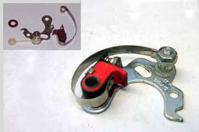
 Just for completeness, the points for the V8 35D8 distributor. August 2021: Wondering when I had last changed the points and not finding a record of a replacement spare set since 1995 (!) I thought I probably ought to change them, and found the contact surfaces in remarkably good condition. Subsequently found the original of the above photo taken in March 2008 which was probably when I fitted them, but still 30k ago.
 Bee's points have done at least 12k and possibly as much as 15k miles. I've never touched them since I first fitted them, although I check the dwell at every service and they have been within tolerance every time, which is why I've never had to touch them. Nevertheless I decided I didn't want to go on until they actually did fail, and I felt I had proved (to my own satisfaction if no one else's) that points aren't the trouble they are made out to be. When I took the old points off there was no sign of any spike and pit, which is surprising as they are the earlier 45D non-sliding type which usually suffer from it, there was just a relatively slight indentation in the larger fixed contact. I did notice that they were coated in oil or grease from the felt rubbing pad, so whether that had acted as a spark quench I don't know. Then again one would expect oil or grease on the points to be a bad thing, but it's always gone like a train. The old ones were stamped LUCAS, whereas these are unstamped in a Unipart box marked 'TURKEY'. I hoped that refers to the country and isn't a comment on their quality ... March 2019: In fact in 2009 I got a set of 25D4 springs from Distributor Doctor and fitted that distributor shortly after. Checked for dwell at each service, this year they were 61 degrees compared to the spec of 60 +-3 degrees having done 17,000 miles, so I think I can say they are at least as good as the previous set 45D4 set which did 18k!
 The points are screwed to a points plate, which as described above is being continually twisted back and fore by the vacuum advance module as you move the accelerator pedal. Some manufacturers rely on a sliding contact between the twisting points plate and a fixed backing plate, but as I found out on a Scimitar GTE this can result in an intermittent contact and a misfire just as you accelerate to pull out of a junction, which is most unwelcome. The Lucas 25D4 and 45D4 have a very flexible cloth-covered wire (similar to the 25D4 points wire) between the points plate and the distributor body. This copes very well with the twisting action for many years, but eventually will fray and/or fracture giving intermittent ignition as described above, and need replacement. The original for the 25D4 is no longer available as one end is spot-welded and crimped to the points plate, Moss Europe list an alternative which in their words may need 'some adaptation' for the 25D4 but should be a direct fit for the 45D4. John Richards seems to have the original type, and Watford Classics seem to have an alternative, both cheaper than Moss and with loop terminals both ends for the 45D4, so the same adaptation may be needed for the 25D4.
Condenser October 2009:
If replacing the condenser or points screw at any time make sure it's not too long or it can foul the weights and cause a misfire.
There are two types of condenser used in the MGB - one with a short wire and bolt-through terminal that connects to the points on the 25D4 distributor used on chrome bumper cars (GCS101), also V8s (GCS108), and one with a longer wire with quick-connect 'terminal' to the points near the condenser and the end of the wire with the male spade going out through the distributor body connecting to the harness on 45D4 distributors used on rubber-bumper cars (GSC110 or GSC2109). Note that parts are usually supplied according to the vehicle year, but as the 25D4 and 45D4 distributors are physically interchangeable you must order the condenser by the type of distributor, not the date of the car.
I've never had a condenser (an old-fashioned term for 'capacitor') fail in 40 years, but I've been carrying a spare in each of my MGBs for probably the whole time I have had them. However current stock from many of the usual suppliers are a different matter and there have been reports of new ones failing within days. For that reason you should always get replacements from a specialist such as Distributor Doctor, ditto rotor arms.
Ignition Theory will explain the function of the condenser, which isn't just to prevent points burning but significantly boosts the energy in the HT and the spark at the plugs. The reduction in points burning is merely a side-effect of putting energy into the spark instead. A diode would be much more effective at quenching the spark at the points, but would greatly reduce the spark at the plugs. When the condenser isn't in circuit the plug spark energy is much reduced but will just about jump a plug gap, but that is 'on the bench' i.e. plug out looking at the gap. Under compression the spark finds it harder to jump the gap and fire the mixture. So it is possible that your engine will start and run, but misfire badly under acceleration. The tach will be relatively steady while this is happening, so you know it isn't anything else in the primary circuit like points, coil primary, ignition supply or connections. Note that this symptom is identical to when the HT circuit is breaking down somewhere, like at the rotor or distributor cap, because the HT voltage has to rise higher before the spark can jump the plug. But if you can reproduce the problem with a timing light connected to the coil lead and plug leads you can isolate it a bit more by watching the flashes as it happens. If the flashes start getting erratic or missing altogether on the plug leads but not the coil lead, then you know the problem is with the cap and/or rotor. If the erratic flashes are on the coil lead as well, then it will be coil or condenser. The condenser is much cheaper (and should be carried as a running spare anyway) than a coil, and you don't even have to disturb the distributor to test the theory. Simply croc-clip the condenser between the points terminal on the coil (white/black) and earth (case to earth although they are not polarity sensitive) and if that solves the problem you know it is the condenser. If not it must be the coil, although coil HT failures seem to be very rare.
It's held that while condenser capacitance (nominally 0.22 micro-farads) can drift, usually with little if any apparent effect on running, when they do fail they usually do so completely and for good. But I have heard of condensers with a poor mechanical connection between the foil and the case or wire, and these could exhibit intermittent or heat-related failure as well as complete and permanent failure.
Testing: If you suspect the condenser compare the spark from flicking the points open by hand, with tapping the distributor wire on and off the coil terminal - ignition on and points closed in both cases. The spark at the points should be far far less than you get by tapping the terminal, and give a better spark at the HT lead. If they are both the same the condenser has failed. To confirm temporarily connect a good condenser between the distributor terminal at the coil and earth. If the engine now starts and runs normally the internal condenser has failed. If it makes no difference either your spare condenser is faulty, or it is something else. Note that having a second working condenser connected for testing will have no adverse effect on a running engine. Obviously if the engine is running normally there is no need to leave it connected, but to give you a quick getaway if your internal condenser should fail you could mount a spare to an earthing point but leave its wire disconnected, ready to connect to the distributor terminal at the coil if needed. You can get purpose-made external condensers, but £25 a pop is ridiculous.
| It's possible to do a crude go/no-go test of a condenser using an ohmmeter. Connect the meter probes to the condenser one way round, then connect them the other way round. Each time you reconnect them you should see a pulse on the meter needle or change in digital display. Note that the pulse will be bigger on reconnecting than on first connecting, so you may not see anything happen on the first connection. |
Rotor Phasing
Rotor problems:
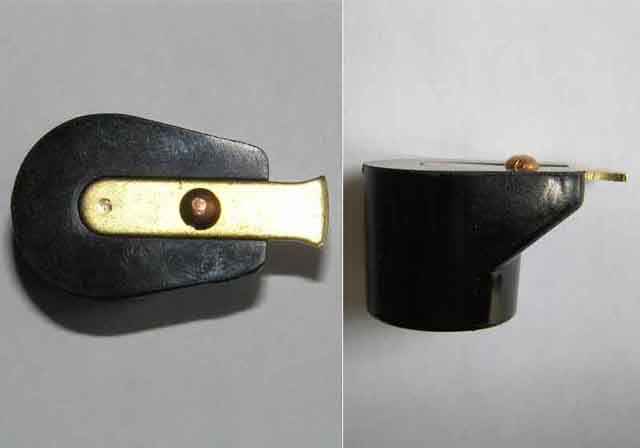
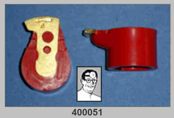
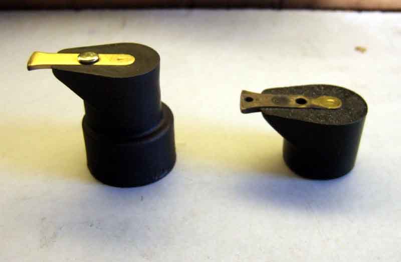 There seems to be a problem with current rotors, at least from some manufacturers, breaking down after a short period of use. The problem could be caused by the round-headed rivet as on the rotor on the left in this image (click thumbnail) being too close to the distributor shaft when fitted. If the line of the rivet is outside the circular base of the rotor body, i.e. more than halfway from the centre of the rotor contact to its tip, it should be OK. Note the rotor on the left in this case is from an aftermarket electronic ignition system and has magnets to operate a Hall-effect trigger in the collar at the bottom and hence is deeper than normal.
December 2009: You can test a rotor for breakdown as follows. Remove the coil lead from the distributor cap and the cap from the distributor. Turn the engine until the points are closed, if not already so. Turn on the ignition, hold the free end of the coil lead about 1/8" away from the brass part of the rotor while you flick the points open. If a spark jumps the gap the rotor has broken down. NOTE: If the rotor has not broken down then a very high voltage will be developed at the coil lead so an insulated implement should be used to hold the lead, even by its insulation.
January 2010: Note that it is normal for a rotor to show burning along its curved edge as the plug jumps a gap between it and the contact inside the cap as well as at the plugs. Note also that the burning is usually along a significant part of the curved face as the relationship between rotor and cap contact changes with vacuum advance (see 'phasing'). Ideally it should be central with a clean area at either end, but I've never seen this in practice, it being biased to one end. Potentially this means the rotor could just have passed (or not quite reached) the cap contact as the spark occurs. If this gap gets too big it could stop plugs firing, and note this effect has been seen with some electronic triggers.
April 2010:
 Another failure, this time within hours of installation. This has a domed rivet a bit further away from the shaft, but not as far as some. Distributor Doctor discusses this problem putting it partly down to a more conductive insulation medium, and a long rivet which is too close to the spring (which is against the shaft). He puts the higher conductivity down to a higher carbon-black content, but carbon-black - despite the implication in its name i.e. carbon rods being used in arc-lamps and dry-cell batteries - when used as a dye as here, is non-conductive. Two other forum threads on the problem from British-Cars.net and the Marlin Owners Club. However the original poster on the British-Cars.net includes a photo of three failed rotors, one of which looks to be the problem style, but another looks to be an original 'no rivet' style and the third is very similar to the Distributor Doctor's TR style with the 'rivet' miles away from the shaft. There has to be suspicion of some other problem in that case, maybe excessive plug gap causing a raised HT voltage.
March 2013:
 In the last year or so 'red' rotors have become available from Distributor Doctor which have an improved insulator in red material and no rivet, and these are the ones to go for. However at Stoneleigh in February I was struck by just how many people had red rotors for sale, and it occurred to me that the unscrupulous will almost certainly start making inferior rotors with red insulators. I go to Distributor Doctors site while writing this update and sure enough that's exactly what he says is now happening, and he is having to emboss his with 'DD'. So go for the supplier, not just the colour.
September 2020: If that wasn't enough it seems that some rotors have an internal resistor that can fail, although possibly only for more modern applications than the MGB, and as it seems to be from German legislation possibly more likely to be Bosch items. Typically 5k ohms but can be less, it serves the same purpose as suppressed leads or caps, but if you have those plus the resistor rotor plus resistor plugs you could start to impact on spark energy.
Rotor Phasing
I first wrote the following in response to someone who wanted to fit a Crane system with electronic trigger but had lost the information on how to adjust the position of the trigger to obtain the correct 'rotor phasing', which is the relationship between cap, rotor and trigger. It is not normally an issue for points systems.
When vacuum advance is applied the points plate moves clockwise relative to the dizzie cam and the rotor arm, and this causes the spark to occur at different relative positions of rotor and cap. You can see the effects of this movement by looking at the edge of the rotor arm. You should see that quite a large part of it shows some burning, this is normal. If the phasing were incorrect the spark could occur before the rotor had reached the cap contact, or after it had left it, and hence you could lose HT. In fact I notice from one of my rotor arms that the burning goes from the middle right up to one edge. This could be causing loss of HT at one extreme of vacuum advance or the other, but since I have never noticed a misfire I assume my points must be right at the limit of correct phasing. Ideally the full range of movement would, occur within the centre section of the rotor arm leaving small unburnt areas either side.
I have a bench rig that I use for testing centrifugal and vacuum advance of distributors so it was relatively easy to connect the coil direct to a plug and with the distributor cap off use a timing light to show me where the rotor arm is when the points open. Of course, the timing light flashes four times in each revolution, hence 'freezes' the rotor arm in four positions instead of one. I would imagine you could get a similar effect on the engine as follows: Remove the plugs to make life easier for the starter and battery and connect the output of the coil to a plug laying on the block somewhere. Disconnect the vacuum advance pipe. With the cap on, wrap a piece of stiff wire around the body of the distributor with one end laying up the side of the cap right in line with one of the plug leads - doesn't matter which one, whichever is easiest to see, then remove the cap being careful not to disturb your wire 'pointer'.
Crank the engine and with a timing light connected to the coil wire (note that a 12v timing light may need to be powered from a separate battery or car to work reliably when cranking) point it at the rotor and you should see it 'frozen' in four positions. Adjust your trigger so that your pointer wire is near the trailing edge of the rotor arm contact. If it is too near the leading edge then when vacuum advance kicks in the rotor arm will move away from the plug lead contact in the cap when the spark occurs and could interrupt the HT.
Depending on how hard you can suck you may be able to create enough vacuum to move the points plate, in which case you should see the rotor arm appear to move in a clockwise direction in the flash of the timing light. If you have a MityVac, or can get your fingers or a lever in there without getting in the way of the rotor arm, twist the points-plate against the spring-loading of the vacuum module as far as it will go and make sure your wire pointer is still within the width of the rotor arm contact.
August 2013:
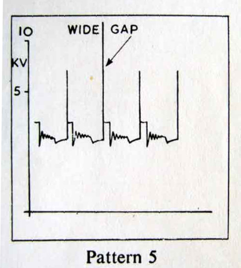 If you have access to an oscilloscope then you may be able to see the effect of the rotor moving away from the cap contact by there being an increase in HT voltage between minimum vacuum advance and maximum vacuum advance - click the thumbnail to see the likely effect of this. Peak HT voltage is more a factor of the air gaps in the system - usually considered to be the plug gaps - than advertised coil voltage, but there is the (normally) small gap between the rotor and the cap contact to be considered as well. If your rotor moves away from the cap contact during HT pulses then this gap gets larger, and the measured HT voltage will increase. You don't need to make electrical contact between the oscilloscope probe and the HT lead (indeed it would be unusual for anything other than an engine analyser to be able to cope with voltages of 10kV or so), just physically attach the probe to the outside of the insulation somehow, and that should be enough to pick up radiated energy with the oscilloscope switched to a suitably low input voltage.
I also wondered about the effects of centrifugal advance on phasing. I came to the conclusion that because the relationship between cam and points doesn't change with centrifugal advance like it does with vacuum advance, then the phasing doesn't change either, and indeed was able to confirm that on the bench.
Added January 2010: Note that with a fully electronic distributor like the 123 both centrifugal and vacuum advance will change the phasing i.e. the relationship between rotor and cap because the distributor shaft is solid (no weights or springs) and both cause the trigger point to be advanced electronically.
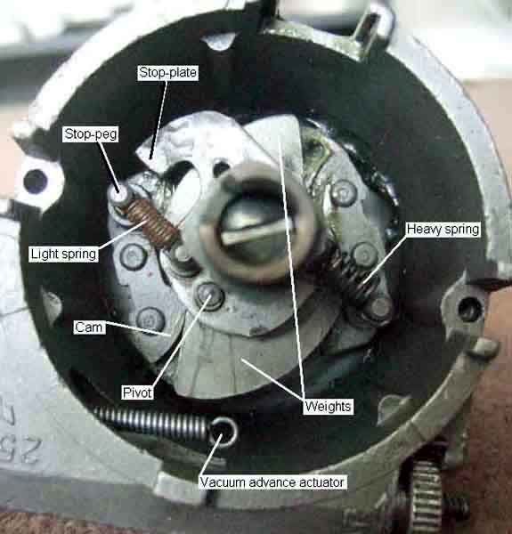
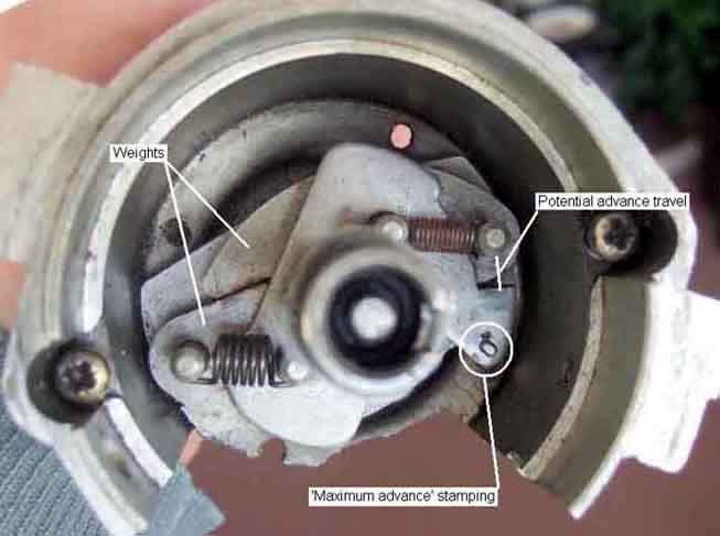 Centrifugal advance is obtained by turning the upper part of the distributor shaft, carrying the points cam, relative to the lower part of the shaft and hence the position of the crankshaft and the pistons in the cylinders. Because the distributor rotates anti-clockwise, centrifugal advance turns the upper part of the shaft also anti-clockwise relative to the lower part, to open the points sooner for a given position of the piston in the cylinder and hence advance the timing. The lower part of the shaft has a pair of weights restrained by springs. The faster the shaft spins the more the weights will try to fly out, up to a maximum controlled by a stop-plate. The springs give a varying amount of advance through the rpm range depending on their strength and other factors. One of those factors usually relies on there being two different springs - a weak and a strong, the weak being 'tight' on its mounting posts and the strong being loose i.e. having free play. This means that as the distributor spins up from a standstill only the weak spring is restraining the weights, so they move out a relatively large amount, advancing the timing a relatively large amount for each step increase in rpm. This movement eventually takes up the free play in the strong spring, then that is also restraining the weights, so the same step increase in rpm moves the weights out and advances the timing a relatively smaller amount than before. This gives the curve its characteristic 'knee' which can be seen - in varying positions on the rpm range and to varying degrees - in most if not all MGB distributors.
Vacuum Advance Added January 2008
Positioning
Vacuum Source
Transmission Controlled Vacuum Advance (TCSA)
V8 Vacuum Module
Carb vs Manifold Vacuum
General description:
 As described here the vacuum module is part of the system that changes the spark timing according to various conditions pertaining at the time. Specifically, it adds more advance under cruising conditions and a light throttle, and less under acceleration i.e. a heavier throttle. There is a difference between the vacuum and hence amount of added advance at idle depending on whether the vacuum source is a carb (prior to 1971 North America, 1975 RHD) or the inlet manifold but that is purely an emissions measure and doesn't affect running, off idle the conditions are the same.
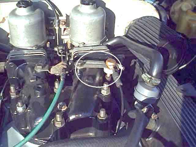
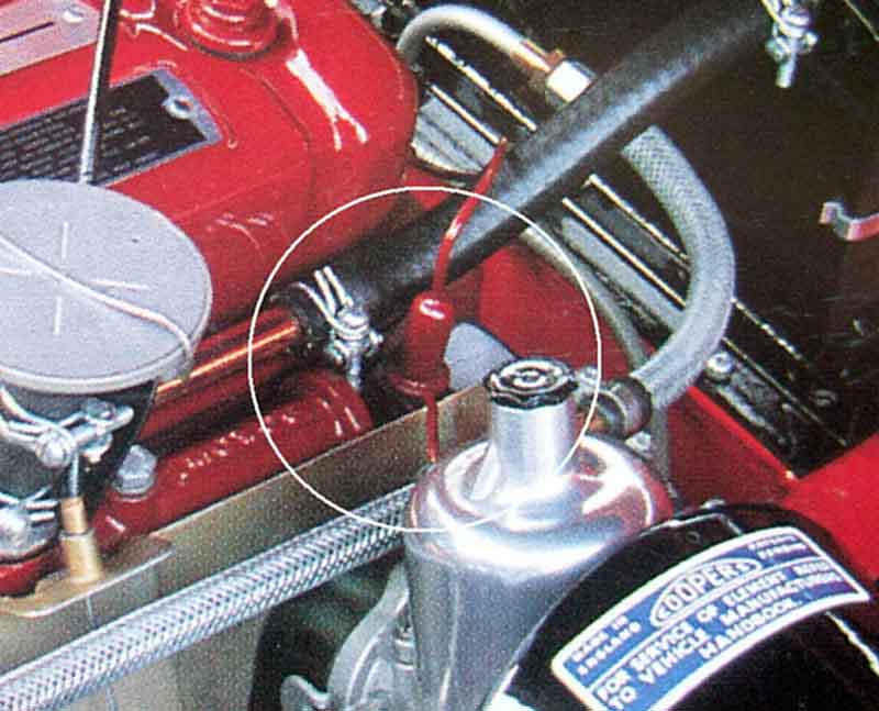 Mk1 cars used a copper tube with fuel trap to connect the rear carb to the vacuum module, Mk2 used a plastic tube with rubber connectors at each end.
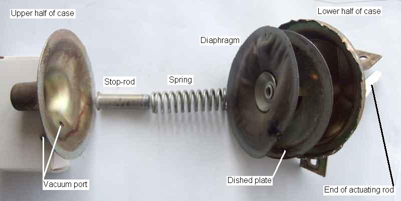 The vacuum module consists of a flexible diaphragm in a chamber which is open to atmosphere on the distributor side and sealed on the suction side. The suction side has a port which was originally piped to the top of the rear carb on HS carbs on 4-cylinder models, moving to the inlet manifold on North American and other export models from August 1971 when they gained 18V engines and HIF carbs, but not until September 1976 on UK cars even though they gained HIF carbs - the rear carb having the port underneath - in November 73. V8s were always connected to the nearside carb underneath. On the vacuum side of the diaphragm there is a coiled return spring. The strength of this spring determines how far the actuating lever will move the points plate under a given amount of vacuum. How much this spring is compressed at rest, in conjunction with its strength, also controls how much vacuum is required to start moving the diaphragm. Inside the spring is a stop-bar, the length of which determines the maximum amount the diaphragm can move, and hence the maximum additional vacuum advance that can be applied. An actuating lever is attached to the distributor side of the diaphragm, which locates on a pin on the points plate inside the distributor, to twist it clockwise (on the 4-cylinder, anti-clockwise on the V8) as the level of vacuum increases, which causes the points to open sooner and so advance the timing. As vacuum advance is applied the relationship between the points (or other trigger) and the rotor is changed, so the HT spark will occur when a different part of the rotor is adjacent to the cap contact (see 'phasing'). This is why rotor contacts are usually an arc, some longer than others. If changing the vacuum advance characteristics i.e. increasing the amount of vacuum advance that is applied make sure the rotor arc is long enough or you could get HT problems at one extreme of vacuum advance or the other, if the rotor contact starts moving away from the cap contact when the spark occurs. If replacing a rotor, make sure the new one has at least as wide an arc as the old one.
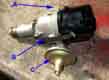
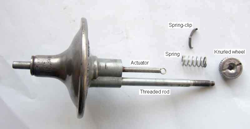 The module for the 25D distributor had a knurled adjuster wheel on a threaded rod which allows the whole module to be moved in and out of the distributor body by a certain amount. This effectively alters the static timing, and hence the starting point for both centrifugal and vacuum advance curves. Originally this was to cope with varying grades of fuel which might be encountered when touring, when the majority of fuel supply was from small independent suppliers (originally chemists!) and fuel quality and octane rating could be very variable. With the spread of national and international chains of filling stations and standardisation and quality control of fuel grades many years ago the need for this adjustment vanished, which was probably one of the reasons why the 45D was introduced with a fixed vacuum capsule (another being cost-reduction as ever). However it is relevant again with the very low octane rating of standard unleaded (95) compared to the original 4-star leaded (99+), and even Super unleaded may only be 97 or 98 octane from some suppliers. Whilst national and international chains of petrol stations usually have both grades, the smaller independents particularly in rural areas often don't. So if you have your timing set to run on Super, you will usually get significant pinking on 95 with a high compression engine, and I have had to adjust the timing when touring Scotland in the past. If I'd had a 25D installed at that time it would have made it much easier, as it was I had a 45D so it was out with the spanners. It depends on how many serrations you have around the edge of your knurled wheel and hence how many clicks for a full turn, but typically about 10 clicks equals one degree of timing adjustment. Mine has 35 serrations, and can go through 7 full turns, which gives plus or minus 12 degrees timing adjustment from a central position.
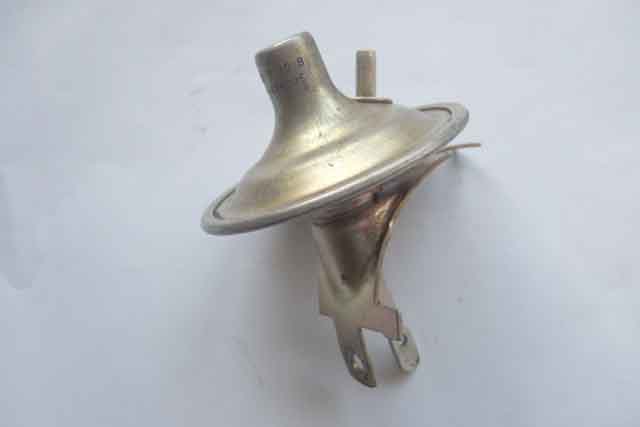
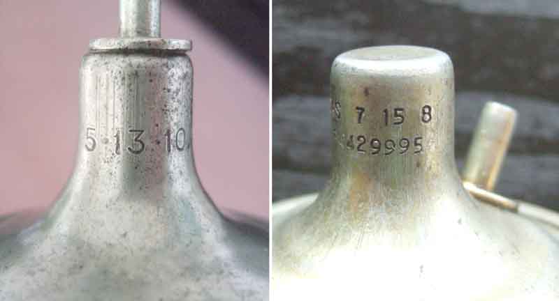 The characteristics of the module are stamped on the upper casing as three groups of numbers e.g. '7 15 8'. In this example vacuum advance will start to be applied at 7 in. Hg. of vacuum, maximum vacuum advance will occur at 15 in. Hg., and the maximum amount of advance that will applied is 8 degrees. This is 8 distributor degrees, which doubles when read at the crankshaft i.e. to 16 degrees in this example. MGB vacuum modules vary considerably. Vacuum advance can start at anything from 3 to 10 in. Hg., maximum advance can be reached at anything from 8 to 15 in. Hg., and the maximum additional advance that can be applied ranges from 6 to 24 crankshaft degrees. The V8 distributor starts at 5, finishes at 17, and applies 16 crankshaft degrees.
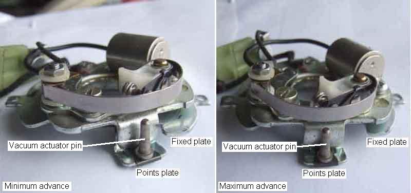 The vacuum capsule changes the timing by pulling and pushing on a pin on the points plate, which twists it and changes the relative position of the points and the cam. When vacuum is applied to the capsule it pulls on its rod, which twists the points plate clockwise (on the 4-cylinder, anti-clockwise on the V8), which advances the points relative to the cam and so advances the timing. 45D4 distributors with sliding points have an additional feature whereby as the points plate twists a fixed pin acts in a slotted cam on the points, which causes the moving contact to move up and down relative to the fixed contact as the vacuum and hence the amount of vacuum advance changes. This means the point are continually making and breaking at different points on their surfaces, which reduces if not eliminates the pitting and spiking of old.
November 2022: As I need to replace some of the vacuum connections on the V8 I did some browsing. Early cars had a copper pipe 12H733 with a cylindrical 'fuel trap' mounted in bracket 11H841 between the top of the rear carb and the vacuum capsule with a straight rubber connector ACH9041 at the carb and a screwed connection at the capsule. Subsequently plastic tubing 37H4229 was used with either a straight rubber connector 12B2095 at each end or on 18V engines one right-angle rubber connector 12B2062 at the carb (under the carb with HIF, later inlet manifold) and one straight 12B2095 at the capsule. No fuel trap probably because with the port at the top even with the right-angle connector any fuel should always run back into the carb, and I've never had a problem with capsules on the 4-cylinder. V8s use right-angle connector 12B2062 at the carb and straight 12B20956 at the capsule, and with the carb port underneath on the HIFs and the pipe angled downwards all the way to the capsule fuel can run down and rot the capsule diaphragm.
June 2016: It should be noted that this continual twisting back and fore as you move the accelerator pedal can eventually fracture two wires inside the distributor. One of these is the points wire that passes through the distributor body of course, and the other is a less obvious earth wire between the points plate and the distributor body. On 25D4 distributors the points wire is a short length of very flexible brown cloth-insulated wire from the spade terminal to the points, but on 45D4 distributors it is a longer grommeted wire that passes through a hole in the distributor body to a male spade terminal which connects to the harness, and internally goes to a tag that attaches to the points and on to the condenser. A new condenser is required if the wire fails. On both types the earth wire is the same type of very flexible brown cloth-covered wire as the 25D4 points wire, see here.
Positioning: May 2024
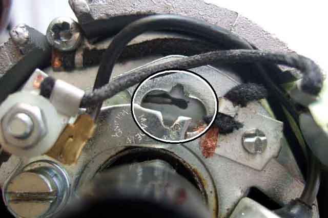
 I'm surprised at the variation in vacuum capsule positioning in various photos. The normal position of the rotor is at about 2 o'clock when pointing to the cap contact for No.1 cylinder when that cylinder is at TDC on its compression stroke. Because it's a 4-cylinder there can only be four possible positions for the distributor body to be positioned when the points open each at 90 degree positions. So I can understand the rotor and hence the distributor body and vacuum capsule being in any of those four positions - only one of which is 'correct', but Clausager shows it anywhere in a 90 degree arc from about 11 o'clock to about 2 o'clock - how can that be? One variable concerns the drive gear position. This also only has one 'correct' position and the distributor can only fully engage with the gear in one rotational position. The WSM describes how to install the gear correctly but Haynes is incorrect which puts the rotor 180 degrees out. Also the distributor could have been dismantled and the two halves of the shaft assembled incorrectly and this also puts the rotor 180 degrees out. The drive gear has at least eight (maybe 9, I've not been able to see clearly from photos) teeth so that it can be inserted in as many positions as there are teeth, only one of which is correct, giving seven (or eight) incorrect positions which will affect exactly where the rotor points for No.1 cylinder, and hence affects the orientation of the distributor body and vacuum capsule for when the points open. Another source of variation is on the 25D4 with it's vernier adjustment giving a timing range of plus or minus 10 degrees for the same distributor and hence vacuum capsule position. Yet another is known to come from some electronic ignition modules which can have a significantly different 'trigger point' i.e. spark generation compared to the points they have replaced and the distributor has to be twisted to get the timing back to how it should be. In extreme cases that can put the rotor away from the cap contact at the point of firing and the spark has to jump a much bigger gap. It would be interesting to see the rotor positions for the variations in capsule position. 45D4 capsules have the port coming off the capsule at an angle instead of off the end for 25D4 so that may have an impact on what fouls and what doesn't.
Someone on the MGOC forum was having problems adjusting his timing by twisting the distributor body as the vacuum capsule tube was fouling the oil gauge hose from the block. In that case his was 90 degrees out so it was a case of turning the distributor 90 degrees clockwise, then moving all the leads round one position anti-clockwise, which kept the firing positions the same, and the capsule was then pointing upwards. With a 25D4 by positioning the vernier adjuster in the middle of its range before resetting the timing would give the best range of 'easy' adjustment in the future.
Transmission Controlled Vacuum Advance (TCSA): April 2013
 North American spec cars from late 76 had a system of inhibiting vacuum advance until 4th gear was selected. Clausager says this was to prevent the engine surging when the clutch was operated, which was presumably an unwanted by-product of all the emissions equipment that had been added to the cars by then. This consisted of a vacuum switch or solenoid in the vacuum pipe between the inlet manifold and the distributor, which when unpowered disconnects manifold vacuum from the distributor. With the solenoid released the distributor side is opened to atmosphere to dissipate any vacuum already in the vacuum advance capsule. The solenoid was energised, to connect vacuum to the distributor, by a switch or switches on the gearbox that only operated in 4th gear. The diagrams show a third gearbox switch, possibly this microswitch that operates in Reverse, 2nd and 4th, in series with the overdrive inhibitor switch that still operated in 3rd and 4th. Thus power was only supplied to the TCSA solenoid when the gearbox was in 4th gear. Whether the additional switch proved unreliable, or whether it was simply penny-pinching I don't know, but it wasn't long before the microswitch was deleted and the overdrive inhibitor switch modified (like V8s) to operate in 4th gear only, powering both the TCSA and the overdrive. By this time the manual switch for the overdrive was on the gear lever, and that circuit was ignition supply - gearbox switch - manual switch - overdrive solenoid so overdrive could still be manually switched on and off in 4th gear. The TCSA feed came off the gearbox switch i.e. before the OD manual switch, so the TCSA solenoid was powered all the time in 4th gear.
V8 Vacuum Module:
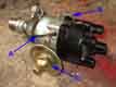
I have had to replace this unit (608194A) twice in the first eight years owning Vee and they are very expensive - in the region of £35 a time. In both cases petrol had caused the rubberised diaphragm inside the unit to shrink and pull out of the seal, which allows outside air to be drawn up the vacuum pipe into the carb. This results in a weak mixture on one carb as well as no vacuum advance when cruising. Having said that I noticed no difference in running, performance or economy when they had failed and only detected it when checking the distributor at routine servicing.
I think this occurs because on the V8 HIF the vacuum port is on the bottom of the carb throat, therefore any liquid fuel in that area will run into the port and from there along the pipe to the module, which is downhill all the way. I notice early MGBs with the copper vacuum pipe have a chamber near the carb end of the pipe attached to a head bolt or similar which is described as a 'fuel trap'. This is also positioned above the carb throat so will have the same effect. But my roadster has the plain plastic pipe and as I say hasn't had the same problem, almost certainly because the carb port in HSs is on top of the throat and the pipe runs up before it goes down to the distributor so fuel cannot get into it anyway.
Someone mentioned getting a fuel or vapour separator as used on some later BL cars but when I went to the MG Rover dealership they were very unhelpful insisting I give them model details before they would look on the computer, so after the second replacement I decided to make something myself.
I reckoned all I needed was a small chamber, mounted higher than the carb port, and with the carb pipe going in the bottom and the distributor pipe coming out the top. So even when fuel pools in the port and the first section of pipe it should never get high enough in the chamber to reach the top pipe and run down to the distributor, carb suction and the relative heights being enough keep the distributor section of the pipe clear.
 Amongst my treasure trove of bits I found a cap used to seal off the end off the open end of 1/2" copper water pipe. I cut out a disc of copper to seal the open end and soldered it on to make the chamber, soldered a short piece of steel brake pipe vertically into the bottom as the 'inlet' (carb) and another piece horizontally near the top for the 'outlet' (module). I did one vertically and one horizontally so I could use the same rubber connectors as used at the V8 carb and module i.e. one angled and one straight. Originally this was so I could get a pair of V8 items knowing they would fit but then I noticed an old 1.0L Metro engine I have kicking around in the garage uses the identical items. Unfortunately the angled one split shortly after fitting but at least I could quote the Metro at the MG Rover Parts place instead of getting an old-fashioned look when I quoted the V8. Got a shock when he quoted the price though, about a tenner, even the salesman was embarrassed.
I made a bracket that bolted under one of the accelerator cable bracket bolts, shaped such that I could clamp the cylindrical body of my chamber to it using a worm-clip, cutting the plastic vacuum pipe in a suitable place for the two rubber connectors. The position of the chamber is such that the whole of it and the angled connector is well above the bottom of the carb port, the top of the chamber being just about level with the top of the carb mounting flanges, so there should be no chance of fuel getting into the chamber, let alone high enough to get into the distributor pipe. Time will tell. Click on the pictures at the left for enlarged views of the general construction and placement.
November 2022: That seems to have worked well for many years but then investigated different dynamic timing measurements at successive routine services - despite the car running better on 97-99 octane now than she had ever done on the 95 she had always used! Rotor was free - twisted anti-clockwise (this distributor rotates clockwise) it flicked back with no hesitation and negligible slop. Sucked on the vacuum pipe at the capsule (easier to get at that at the carb) and it did not move the points plate, and only holding a bit of vacuum. Pushing at the points plate with a screwdriver it moved, but seem to require a lot of force. So capsule suspect again as well as possibly the points plate. But one of the rubber connectors on my separation chamber is perished with splits showing so the first job is to replace all four of them. The one at the capsule had always been held on with a cable-tie, I maybe should have replaced that years ago but the points plate was moving originally so was obviously sealing and given the cost at the time wasn't worth it! With the benefit of the internet now not only do the usual suspects give the original part numbers, but Googling the numbers reveals a whole raft of suppliers, with prices now less than £2 each. The usual suspects and some eBay sources add a fair bit on for P&P, but Wood & Picket have both the right-angle and the straight for that price with free 3-day postage. I get two of each with my separation chamber, and get a 10p discount off the total price into the bargain. Current prices for the capsule 608194A range from £46 inc VAT and P&P from Clive Wheatley up to £150 plus £30 P&P from Italy! One MG supplier does have them at £39 inc VAT plus P&P but I refuse to use them as they have repeatedly supplied faulty or incorrect parts. But I'll wait for the connectors, and check the full length before splashing out on one of those.
Any road up, as they say, the W&P items arrive just a couple of days later. I'd not investigated the old ones until they arrived - no point taking them off only to have to put them back if I could use the car, but took them off now. The long distributor pipe with the two straight connectors leaked when sucked - both split and replaced. Back on the capsule, sucked, and the points plate was moving as it should - result, £50 not needing to be spent! The two right-angle ones on the short carb pipe held a vacuum, but they were a sloppy fit on the fuel trap pipe at least so both those replaced as well. Tested the full length through the fuel trap to the distributor and points plate still moving so all good now, and confirmation that the fuel trap has done its job as that capsule has been in 20 years now.
Carb vs Manifold Vacuum:
After many years of discussion over the differences - can a carb distributor be used on a manifold engine? (Yes
and vice-versa) Is one vacuum advance and the other vacuum retard? (No, they are both vacuum advance) Are the vacuum advance curves completely different depending on connection? (Not when running, only at idle and just off it) - I decided to do some tests to show how little difference there really is between the two and that any distributor can be carb connected or manifold connected.
The first thing to reiterate is that it doesn't matter whether a distributor was fitted to an engine with carb vacuum or manifold vacuum, the advance mechanism in the distributor is identical - the more vacuum that is applied the more advance is applied and vice-versa.
 The second is that the only difference between the two is at idle and just off it. Manifold vacuum is high at idle
reducing to almost zero as the throttle is moved towards fully open. Carb vacuum is zero at idle as the butterfly plate covers the port and the port is effectively on the piston or low-vacuum side of the butterfly. As the throttle starts to open the port is uncovered and is effectively moved to the same side of the butterfly as the manifold port i.e. the high-vacuum side. Therefore the vacuum rises very rapidly, and when the throttle is only slightly open it becomes the same as manifold vacuum, thereafter it reduces gradually to almost zero as the throttle is moved towards fully open, exactly as manifold vacuum does.
The second is that the only difference between the two is at idle and just off it. Manifold vacuum is high at idle
reducing to almost zero as the throttle is moved towards fully open. Carb vacuum is zero at idle as the butterfly plate covers the port and the port is effectively on the piston or low-vacuum side of the butterfly. As the throttle starts to open the port is uncovered and is effectively moved to the same side of the butterfly as the manifold port i.e. the high-vacuum side. Therefore the vacuum rises very rapidly, and when the throttle is only slightly open it becomes the same as manifold vacuum, thereafter it reduces gradually to almost zero as the throttle is moved towards fully open, exactly as manifold vacuum does.
I had recently obtained a TCSA vacuum solenoid from Gordie Bird (for some experiments with knock-sensing retard) which I modified slightly to provide a short tube on the atmosphere port in place of the filter. This allows the solenoid to acts as a 'change-over' switch passing vacuum from one of two sources depending on whether the solenoid is powered or not. My car has carb vacuum so that was one source. I have had a vacuum gauge for nearly 40 years that I used to use for tuning as well as economy driving, and had made an adapter to screw in place of one of the blanking plugs on the MGB manifold, so that was the other source. Thus a simple on/off switch taped to the bracing bar behind the dash allowed me to select the vacuum source. I made a 'T' junction and inserted this between the solenoid and the distributor to connect the vacuum gauge so I could see the signal the distributor was receiving. The following two pictures show the vacuum connections to carb and inlet manifold, and the solenoid and its connection from the vacuum sources and to the distributor and vacuum gauge:
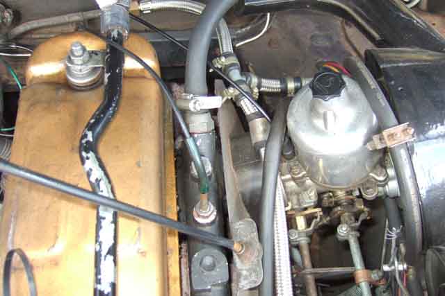
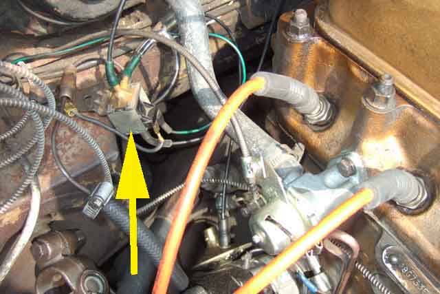
In the cabin I attached the vacuum gauge with a bracket to one of the screws holding the centre console in place
and rigged up a simple pointer that moved across the face of the gauge as the throttle was opened. The next two pictures show zero throttle with the pointer at the left, and full throttle with it at the right (engine off!):
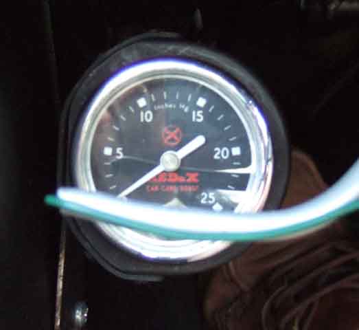
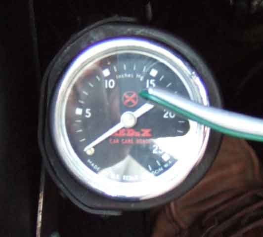
The remaining pictures show the vacuum signal at various speeds and throttle openings, carb signal on the left and manifold on the right. The first pair are at a steady 20mph on the flat in 3rd gear. Even with the very small throttle opening carb vacuum is already at 10 in. Hg. with manifold at 19. Incidentally this manifold reading is higher than at idle as the engine is operating more efficiently:
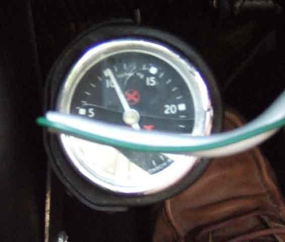
The next pair are at about 25mph on the flat in 3rd gear
now the throttle has opened a bit more carb vacuum has risen to about 13 but manifold has fallen to 17:
The final pair are at about 30mph, and carb and manifold vacuum are virtually identical at about 14 in. Hg.:
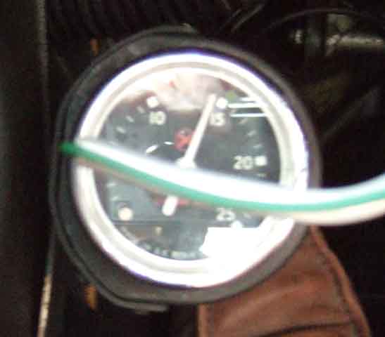
As you can see the throttle opening is still very small from the position of the pointer. At any higher throttle openings the vacuum falls away on both at the same rate. All these readings were taken at a steady speed on the flat. Under light acceleration vacuum will be significantly less than this, and under significant acceleration it will be much lower and the resultant additional advance will be zero. The important thing is that both carb and manifold vacuum give the same results in most normal driving conditions. The only reason for the change is that manifold vacuum results in a higher idle speed than carb vacuum. This allows the idle screws to be backed off slightly to achieve to same idle speed, which reduces fuel consumption and hence pollutants. The final thing to remember is that UK cars didn't get manifold vacuum until September 76, but had the same engine and distributor from the start of rubber bumper production in 1974 to the end of production in 1980. Which itself is surely proof that the two are interchangeable.
See also http://www.iwemalpg.com/Vacuum_gauge.htm which has information on using a vacuum gauge for fault diagnosis.
Distributor Caps Added April 2010
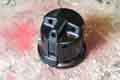 Side-entry (Mk1 originally) for screw-fit leads and top-entry (Mk2 and CB production to November 73) for push-fit leads are available for the 25D4. The side-entry cap accepts leads with cut ends - either suppressed or copper - and are secured in the cap with screws.
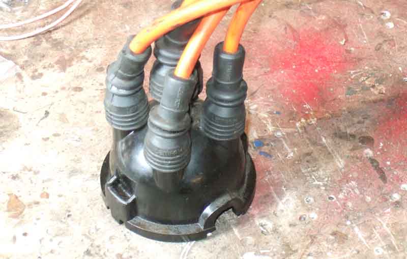 Top-entry types accept ready-made suppressed leads fitted with terminals which are a simple push-fit. Straight cap connections can rub on the steering column UJ on RHD cars but right-angle types are available for both 25D4 and 45D4 which avoid that.
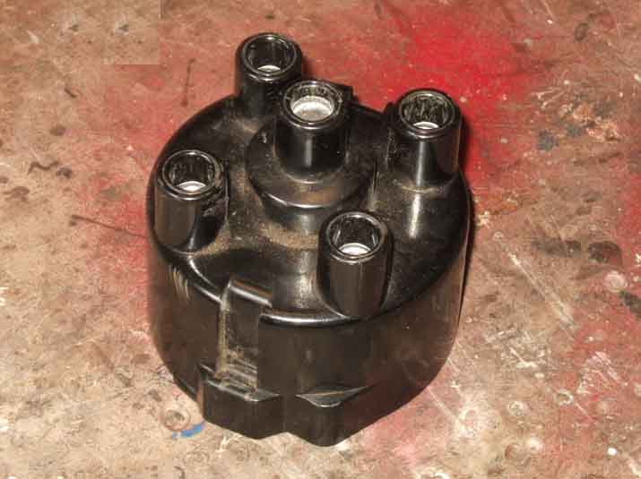 For the 45D4 ( from 18V779/780 in November 73) the cap is GDC132 top-entry push-fit leads. The same cap was used on North American 45DE4 and 45DM4 electronic units but like the 25D4 top-entry on RHD the leads can rub rub on the steering column UJ but again right-angle types are avialable which avoids that.
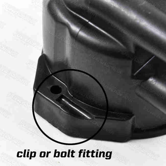 Side-entry versions were used on the classic Mini screwed to the distributor body, but several suppliers show DDB194 side-entry push-fit caps that can be secured with either screws or clips so should be suitable for the MGB.
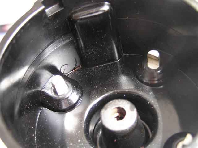 Reports of very early failures of rotors and condensers (sometimes within road-hours of fitting) is becoming all too common, are we also to get similar failures in distributor caps? This relatively new cap lost its carbon contact, then damaging the rotor, requiring replacement of both. The new rotor almost immediately proceeded to give intermittent misfiring shortly before total failure. March 2024: Another example on the same type of 45D4 cap.
February 2015:
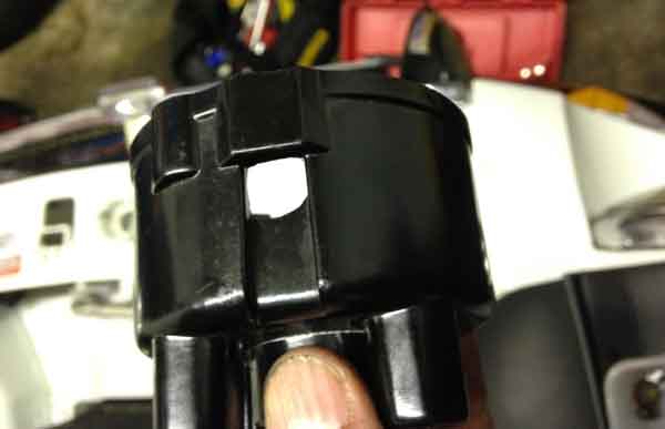 Another new cap failure - Lucas boxed, this time the retaining springs had punched holes through the cap and shorted out the HT.
Firing Order and lead positioning
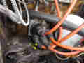 With the top entry cap one of the leads (usually No. 4) exits very close to the steering column UJ and the clamp bolt can hit the lead as the steering is turned. Ben Columb had an intermittent misfire because it was virtually touching and the spark jumped that gap rather than the plug gap. I discovered the rubber boot on one of my leads had been gouged but wasn't causing a misfire - yet - so I routed that lead round the other leads on its way to No.4 plug which keeps it out of the way. The original side-entry cap would be better but I think they only take cut leads, and for the 23/25D4. However there are lead sets with right-angle connectors for both 25D4 and 45D4 which should avoid that. But a down-side may be that you can't slide the boots up the leads at the distributor end to make sure the connectors are fully seated in the cap before sliding the boot back down again, and a right-angle cap on the rear plugs may foul the heater valve. Personally I would rather have right-angles at the cap and straights at the plugs, they do exist, a bit dearer than ANG, but you have to look carefully because some are the other way round i.e. straights at the cap and right-angles at the plugs which would be the worst of both worlds!
For the 45D4 a possibility is cap DDB194 which is a side-entry for push-fit leads. Used on the Mini with screws to attach it to the distributor body a number of sources show this cap with recesses for standard spring-clip fitting. I've not been able to find a side-entry push-fit cap for the 25D4.
V8: 1 8 4 3 6 5 7 2 counting clockwise round the cap, where No.1 is at the front of the left bank i.e. on the right as you look back from the front of the car. Note the Leyland Workshop Manual Supplement states the direction of rotation incorrectly but the drawing is correct.
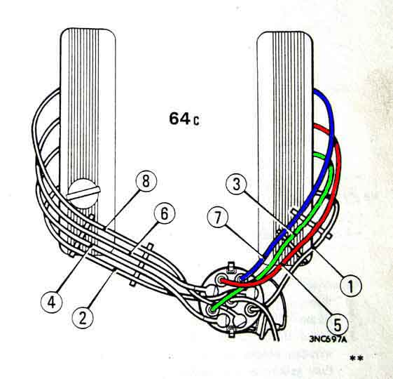 The plug leads are clipped into 'combs' which would normally take the leads as they went to the cylinders from front to back, but 3 and 5 must be swapped over so 5 and 7 and not adjacent. 5 and 7 are next to each other in the firing order, and if the leads are run closely together when 5 fires it can fire 7 prematurely.
One comb each side is 'floating' and one screwed to the top of the rocker cover, with No.8 in a single comb screwed to the side of the rocker cover. Screws unknown although carb piston cover screws (3/4 BSW/Whitworth) fit the thread, albeit a bit shorter and with a flatter slotted head rather than a cross-slotted cheese-head.
Distributor O-rings March 2013
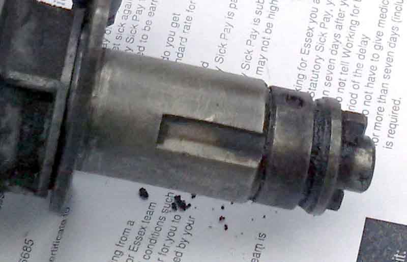 To O? Or not to O? That is the question. My blind pal Terry is just starting to fit the ancillaries to his newly installed engine and I mentioned to check that the distributor had an O-ring fitted. I described where it should be but he just couldn't locate the slot. He sent some pictures and it was immediately obvious his doesn't have one. Googling showed that a number of people said they did have one, and a number didn't, for marques other than MG as well as MG, but no clear statements on the subject (was ever thus). And one claim (in a source that should be world-famous for its mis- and dis-information) that a groove at the bottom of the dizzie body is for an O-ring is completely incorrect. There is one in the drive dog, and one between that and the distributor body. The drive dog rotates of course, and an O-ring here would get ripped to pieces if the housing extended that far, or do absolutely nothing if it didn't.
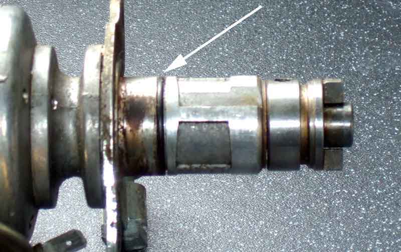 Looking in the Parts Catalogue although all the drawings show a groove and a O-ring, for both 25D and 45D, when you start reading the detail, distributors for early engines are shown having it, also later ones, but there are a batch of 25D4s in the middle that don't show it:
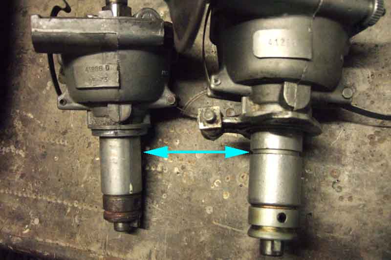 However in July 2016 when I had Bee's engine out to change the clutch and cleaned up the very mucky engine in the process, I've been keeping an eye for any oil trickling down the block after trips. I noticed one under the distributor, which is a 25D4 41228 i.e. for an 18V581/582 and hence shouldn't have the slot. However thinking I may be able to utilise it in some way I bought an O-ring. And on removing the distributor I was quite taken aback to find a slot! However this is a remanufactured unit, so perhaps not surprising it has the slot. So O-ring fitted. The block face the distributor clamp plate butts up to seemed clean, and there are a couple of plugged oil-ways immediately below that so it could be from there. But after a few dozen miles there is no sign of more oil, so O-ring it was. For Mk2 distributors without the slot it may be possible to fit a thicker O-ring in the larger groove right at the top of the shaft, to bear down on the edge of the hole.
With the drive gear inserted correctly the rotor should be pointing at about 2 o'clock when the distributor has been fully seated in the block. If it points to about 8 o'clock the distributor may have been incorrectly assembled, and if to any other position the drive gear has been inserted incorrectly. The distributor body can be rotated - the rotor itself should NOT move - and as well as altering the timing (by moving the points around the cam on the upper part of the shaft) it will change which cap contact is by the rotor when the points open, and that cap contact has to go to No.1 cylinder when the engine has that piston at TDC on its firing stroke.
With TDC and rotor position established there are typically two positions for the distributor body - one with the vacuum capsule pointing to the left of the heater valve and the other two the right. I've not seen any definitive original BL document that shows the distributor in its installed position, Clausager shows them in both, so either can be considered 'correct'. Pointing to the left puts the vacuum pipe towards the rear of the rocker cover instead of over the middle so that may be a factor if you have the metal tube instead of the plastic. Otherwise pointing to the right probably makes access to the lower cap clip easier for flicking it off.
That decided with No.1 lead connected to the cap contact by the rotor fit the others counting ANTI-clockwise round the cap from there 3, 4, 2. Side-entry caps keep the leads clear of the steering column and UJ but top-entry put them very close, I've had to wrap No.4 lead round the others to keep it away from the nut and bolt on the UJ.
Setting initial timing: Static is easiest, some electronic ignition systems have a light to enable this, others don't so you have to go by trial and error to get the engine running then adjust by strobe. For static connect a test-lamp or meter to the points wire and turn the engine in it's normal direction (clockwise looking at the front of the engine) to bring the timing mark towards the pointers on the front cover. This page has the static figure for most if not all the MGB distributors, but it maybe best to use those just as a guide and start closer to TDC. This is because I have found that even with a strobe timing of just a couple of degrees less than the book figure the strobe figure was a full 10 degrees retarded from the book figure, which can be caused by worn i.e. slack distributor springs.
The distributor fits in a circular clamp plate that is bolted to the block. With the clamp loosened the distributor can be turned to any rotational position, there can either be a square-headed bolt that doesn't turn and a hex nut that does, or the other way round. When tightening do not overtighten - with the hex nut the torque figure is only 2.5 ft lb (if the clamp bolt has the hex head it is 4 ft lb), it can apply a lot of force to the alloy shoulder of the distributor body, distort it, and the distributor can jump out of the clamp plate. The holes in the clamp plate for the block screws are elongated which gives a small range of timing adjustment just by slackening the two clamp screws. When initially setting the distributor lightly tighten one of the clamp screws with the clamp plate positioned in the middle of the available adjustment, so small advance and retard adjustments later on can be done within the elongated holes. If needing to turn the distributor further than that it may be necessary to slacken one of the block screws as well as the clamp plate nut to allow the distributor to be turned.
With the 45D4 distributor timing adjustments can only by done by moving the clamp plate relative to the block or twisting the distributor in the clamp plate. The 25D4 has the very useful Vernier adjuster on the vacuum capsule that allows several degrees of timing adjustment just by turning a knurled wheel, nut or screw slackening and body twisting not needed. Again when first installing a distributor set the knurled wheel in the middle of its range of adjustment so future adjustments both advance and retard will almost certainly be within the scope of that wheel.
V8
4-Cylinder:
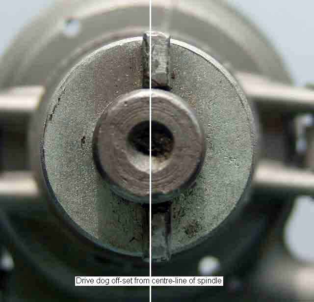 At first sight it would seem that the drive dog on the end of the distributor shaft and the driving slot in the gear in the crankcase would allow the two to be assembled in either of two positions. However they are both offset slightly, by about half the width of the dog/slot, so they will only fully engage in one position. But they are so close that if turning the rotor while pressing the distributor down gently to locate the slot, it will seem to partly engage in the incorrect position. But as said, it will only fully engage in one position, which is when the distributor flange is flush to the clamp plate, and the clamp plate is flush to the block.
Whilst, as long as each plug gets its spark at the correct time, any position on the cap can be used for No.1, the 'correct' position is around 2 o'clock when looking down on the top of the cap whilst standing beside the right-hand wing. The rotor should be pointing at this lead when at TDC (Top Dead Centre) at the end of the compression stroke of No.1 piston, which is at the front (radiator end) of the engine. You can determine TDC either by examination of the valves when turning the engine by hand, or as John Twist describes below. Using the valves the compression stroke is the one where both valves are closed (up) for the majority of the up-stroke of the piston, and also for the expansion down-stroke. To avoid having to remove the rocker cover (damage to gasket, leaks afterwards etc) an alternative is to remove the plugs and turn the engine by hand with your thumb over No.1 plug hole. When you can feel compression blowing past your thumb, that is the compression stroke. When the piston gets to the top of the cylinder on that stroke, that is the firing point for that cylinder. Whichever method you use, wherever the rotor is pointing when the piston is at the top of its compression stroke, the cap contact it lines up with should be wired to No.1 plug. Thereafter the correct firing order is 1-3-4-2 counting round the cap in an anti-clockwise direction.
If the engine has been rebuilt it is possible for the drive gear to be inserted in nine different positions (the number of teeth at the cam end of the gear), only one of which is correct. The rotor can also end up 180 degrees out as the Workshop Manual and Haynes explain things differently and Haynes is incorrect. It can also happen if the distributor has been dismantled and reassembled incorrectly, as apart from knowing the relationship between the drive-dog on the lower half of the shaft and the rotor location notch on the upper half there is nothing else to indicate which way is correct.
Haynes also gives different processes for 18G/GA (3-bearing) engine, 18GB and later (5-bearing) prior to 1978, and another one for 1978 and later, the following three drawings are from Haynes:
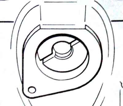 18G/GA - no starting position only how it ends up, with the slot from about 2:00 to 8:00. Not clear which side the slot is offset to, but the text says 'below the horizontal'.
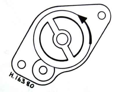 1978 and later starting position - drive gear rotates anti-clockwise as it engages, with a starting position of about 5:00 to 11:00. However John Twist says "drop the gear back into the engine, keyway offset below horizontal, large half of the driving dog uppermost, with the keyway 9:00 to 3:00". .
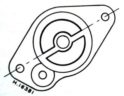 1978 and later finishes up as here with the slot below the horizontal. This is the same as how John Twist describes it "As the gear drops into place, it will rotate anti-clockwise and set in at about 2:00-8:00". John Twist implies only 30 degrees rotation, whereas Haynes shows it more like 90 degrees. The drive gear is the same throughout including 3-bearing engines - 12G4499. Maybe one day I'll take mine out and see.
No drawings for pre-78 5-bearing engines but Haynes says "Position the pistons half-way up the cylinder bores and enter the spindle. Turn the crankshaft (putting No.1 piston at TDC on the compression stroke), withdraw the spindle sufficient to clear the camshaft gear, hold it with the slot horizontal and the small offset at the bottom, and re-enter the gear. Note that as engagement takes place the slot will turn to the 2 o'clock position". Having the slot horizontal before the final insertion is the same as John Twist's 9:00 and 3:00. But why it needs to be initially inserted with the pistons half-way up, then the engine turned to TDC, then the spindle withdrawn, slot positioned horizontally, then reinserted is a bit of a mystery.
DISTRIBUTOR DRIVE GEAR POSITION from John Twist:
August 2019: It's possible to rotate the drive dog on the end of the distributor shaft 180 degrees by driving out the roll-pin, but if the distributor is replaced, or the drive gear or timing gear is corrected, the rotor position will be out again.
V8: The V8 distributor arrangement is completely different to the 4-cylinder - and I don't just mean having twice as many cap contacts. Whereas the 4-cylinder can only go back in one position, the V8 is driven directly by gears from the camshaft so can go back in as many positions as there are teeth on the gears. I know the 4-cylinder also has a drive gear, but that is only disturbed by exception for example during an engine rebuild. The other difference to the 4-cylinder is that whereas the camshaft drives the oil pump and the distributor independently, as said above the V8 camshaft drives the distributor directly, and it's a dog clutch in the shape of a tongue and slot that drives the oil pump. The 4-cylinder drive gear also has a dog clutch to the distributor, but it is offset to one side which means the two can only engage in one rotational position. The V8 distributor can engage with the oil pump in two positions, but that has no impact on anything else. Up to 1976 all Rover V8 engines had the tongue on the distributor and the slot in the oil pump shaft. With the introduction of the SD1 the engines for that car had electronic ignition using a 35DE8 distributor, and this had the slot on the distributor and the tongue on the oil pump shaft. Points engines e.g. Range Rovers changed to the later drive arrangement in 1978, but kept points for a further four years! See Fitting a V8 into an MGB by Roger Parker.
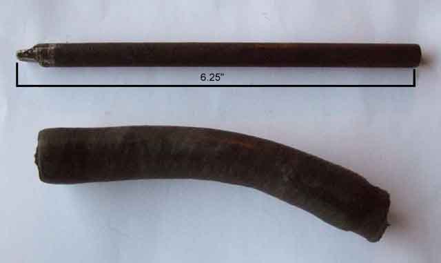 One benefit of either type of drive is that the distributor can be removed and a drill with suitable drive shaft inserted into the hole to drive the oil-pump directly. After a rebuild or any interference with the oil delivery system it is far better to build up oil pressure this way than cranking or even worse running the engine and hoping it eventually shows on the gauge. Have the drill on minimum speed, and I gripped the chuck firmly with my hand as well to slow it even further.
Note: The down-side is that if you crank with the distributor removed the oil pump is disabled!
So when inserting the V8 distributor, not only do you have to ensure that the correct teeth engage to get the rotor pointing to No.1 cap contact at TDC on No.1 compression stroke, you also need the tongue on the distributor to be aligned with the slot on the oil pump before it will fully seat. Just look at the positions of the tongue, and slot you may well say. But as the distributor engages with the camshaft the distributor shaft is turned by about half the distance from one cap contact to the next. So not only do you have to turn the rotor back half a cap contact (or is it forward ...) before you start insertion, you have to set the oil pump slot to where the distributor shaft tongue is going to be once the gears are partially engaged! That's tricky, and you could spend much time tweaking the position of the oil pump shaft before you get it right, and the distributor has to come fully out and go back in each time. It's actually easier to turn the crank bit by bit to get that aligned with the oil pump slot, but you do have to back the distributor out just a fraction or simple friction between the two shafts could turn the oil pump with the distributor, and you get nowhere.
This all has to be done with the engine at TDC on No.1 compression stroke, and of course there is a TDC for its exhaust stroke as well. You can tell which is which from the rockers once the rocker cover has been removed, but another way is to inject compressed air into the cylinder with a modified spark plug body with a Schrader valve attached. Having a compressor and said modified spark plug, that is my preferred approach. The difference between the two TDCs is very clear - on the compression stroke the pressure only bleeds off relatively slowly, whereas on the exhaust stroke is bleeds off pretty-well instantly.
Dwell
V8
What do I set my timing to?
Timing marks
Plotting centrifugal and vacuum curves and dwell electronically by Frodo Irrxsom
4-Cylinder: The points are so difficult to get at with the oil pipe and steering column in the way on RHD cars (it's bad enough just getting the cap off) that I always remove the distributor to check or change them. I also remove it by undoing the two screws that hold the clamp-plate to the block (pulling out the dipstick for better access) and removing distributor and clamp-plate together, rather than slackening the clamp bolt itself. This is for several reasons, the most important of which is that frequently undoing and tightening the clamp bolt can damage the shoulder on the distributor body, which can make it jump out of the clamp when driving. Don't worry about turning the engine or the distributor while it is out, it only goes back in one way, and you are going to have to check and adjust the timing anyway, as the holes in the clamp-plate are large enough to give several degrees of variation in timing and replacing the points or even altering the gap of existing points will change the timing.
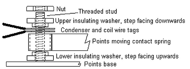 When replacing points where everything is held on with a nut it is vital to get the tags from the condenser and the coil in the right place. Basically, everything except the nut goes between the two insulators i.e. baseplate - insulator (narrow end up so it fits in and locates the points spring) - points spring - condenser tag - coil tag - second insulator (narrow end down so it fits in and locates the two tags and the points spring) - nut. If any of the points spring, condenser tag or coil tag touch the baseplate bolt or the nut the engine will not run. Other distributors have a simpler method of location where the points spring rests against an insulator that rests against a flange on the baseplate, and the condenser and coil wires are connected to the same tag that slips under a fold at the end of the points spring. Less likelihood of getting things in the wrong place.
The points gap is typically set to .014 to .016 using feeler gauges, and measured with the heel of the points on the highest part of the cam such that the gap is at its greatest. There should be light resistance with the .016 gauge and no resistance with the .014 gauge. When checking used points there will often be a spike on the one contact and a hole on the other, in this case using a feeler gauge will result in a much wider gap then intended. It is possible to clean up points with a fine sharpening stone, but once you have them off you may as well fit new ones. When the gap is correct insert a piece of clean paper between the points, close them, pull the paper slightly, open the points and remove the paper - this cleans off any oil etc that might have been transferred from the feeler gauges. Don't pull the paper all the way out with the points closed as this can leave fibres behind that can cause an intermittent misfire.
Dwell:
However dwell is a much more accurate way of checking/setting the points (see here for electronic ignition) than using feeler gauges, and as far as checking goes is far preferable as it is 'non-invasive' i.e. the dwell meter just clips to 12v, earth and the coil CB/-ve terminal so you don't even have to take the cap off let alone put greasy feeler gauges between the contacts. If you don't have a meter with a dwell scale you can use an analogue voltmeter or ammeter, and maybe some digital meters if they have an averaging function - with caveats. The dwell meter is basically measuring the changing voltage at the coil CB/-ve and you can do much the same by connecting a voltmeter between there and a 12v supply such as at the fusebox. With the points closed the meter will show your system voltage (typically 14v with the engine running) and zero volts when they are open. Thus on a running engine the meter will stabilise at a point which shows the proportion of time that the points are closed, just as a dwell meter does. You do need to measure your system voltage first (Vs), then express the displayed 'dwell' voltage (Vd) as a percentage of that, i.e. Vd/Vs*100. As dwell figures are usually given in degrees rather than percent this would have to be converted to degrees, but it's easier to convert the specified dwell degree range to percent once, and compare your percentage reading with that. On a 4-cylinder engine each cylinder occupies 90 degrees of the distributor, so a nominal dwell of 60 degrees (for a 25D4) equates to 60/90*100 or 66.7%, but more usefully the tolerance of +- 3 degrees gives a range of 64% to 70%. For a 45D4 with a nominal dwell of 51 degrees and +- 5 degrees tolerance (the lower figure coming from the use of more efficient coils and enables them to run cooler) gives a range of 51% to 62%. On a V8 each cylinder occupies 45 degrees of distributor rotation, so with a nominal dwell of 27 degrees you get 27/45*100 i.e. 60 degrees, and with +-1 degree of tolerance (a factor of having double the number of lobes in the same 'space') you get a range of 58% to 62%. You can do a similar thing with an ammeter inserted in series with the coil, using the standing points closed current in place of the system voltage.
The caveat referred to above means that voltage and current can only be used as a guide to dwell, and do not exactly replicate a dwell meter. This is because the measured voltage or current is modified by the voltage surges that occur as the points open, which the dwell meter has been designed to ignore. For example the Workshop Manual quotes the points closed current of a 12v ignition system as 3.9 amps, which represents a nominal 3.3 ohm coil being powered at 13v. It then quotes the running current as 1.4 amps, which is only 36% of 3.9 amps, and not 67% (calculated from the stated dwell above) as one might expect. It also quotes that current at 2000rpm, as additionally the readings change as engine speed changes. Hence saying above that use of a voltmeter or an ammeter is only a guide. The Workshop Manual would have used an analogue meter, digital meters may give different results or no usable result at all depending on type. I have taken dwell, voltage and current readings using an analogue meter on the CB roadster (12v ignition system) and the V8 (ballasted system) and the results were as follows:
| Ignition System | Measured dwell (book dwell) | 1000rpm | 2000rpm | ||||||||
(57-63 deg) (26-28 deg) | |||||||||||
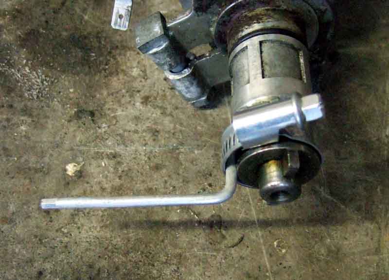 If removing the distributor to replace the points on the face of it you can't set the gap with dwell until it is back in the car - unless you make a bench-test rig. In its simplest form this can just be an 'arm' such as a small Allen key lightly clamped to the rotating part of the shaft with a Jubilee-clip, that you rotate with a finger-tip, and an analogue ohmmeter. A little-known feature of analogue ohmmeters is that on a regularly interrupted circuit such as points, if the distributor shaft is turned fast enough the damping of the meter needle is such that it will indicate a relatively steady average value between infinity (a zero reading) and zero ohms (full-scale deflection). Note that an ohmmeter can't be used on-car with a running engine as the ignition voltage interferes with the internal battery of the ohmmeter, and is primarily of use for testing on the bench, and because of that it does not suffer from the voltage and current caveat referred to above. The position of the needle represents the percentage time that the points are closed, between 0% and 100%, which can be used as a direct comparison with the percentage figures calculated above i.e. 64% to 70% for a 25D4, 51% to 62% for a 45D4, and 58% to 62% for a 35D8. If you have an analogue ohmmeter with a 10v (or 100v) full deflection scale, you can read the percentage dwell off that, even though the meter is switched to ohms. If you have a 10v scale multiply the reading by 10, and if you don't have a 10v or 100v scale use an appropriate scaling factor with a scale you do have. I.e. if you have a 30v full deflection scale you will be looking for a value on that 3.3 times higher than you would on a 10v scale. Rotate the 'arm' on the shaft of the distributor with your finger-tip fast enough to get a useable reading, and simply read off your percentage dwell. Tweak points and repeat, ad infinitum.
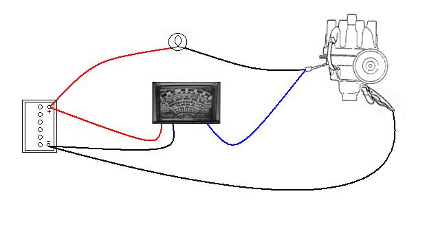 Confused? No worries, if you have a dwell meter showing degrees you can use that on the bench as well! This will need a battery and a load simulating the coil such as a 12v bulb, as well as the dwell meter. One side of the battery goes to one side of the bulb, the other side of the bulb goes to the points wire of the distributor, and the body of the distributor goes to the other side of the battery, such that as the distributor rotates the bulb switches on and off. It doesn't matter which way round you connect the battery to your bulb and distributor but it makes sense to use the same polarity as your car to make things simpler. As to what voltage battery to use, you may be able to get away with a low-voltage dry-cell battery, or you may need a 12v source. With the circuit connected up as described turn the distributor to open the points and the meter should show zero. Turn the distributor to close the points, and an analogue dwell meter should show full scale deflection, a digital switched to 4-cylinder and degrees should show 90 (360 divided by 4 remember?). If you find either meter shows less than this (they expect to be working at 12-14v) then you will have to use a 12v-14v battery, which again could be a series of dry cells (when using dry cells use a low wattage 12v bulb such as a 2.2w instrument bulb to avoid flattening the battery too quickly). You probably won't be able to use a battery charger on its own as these generally output rectified AC which is a series of voltage pulses at 50 or 100 Hz, and when the voltage from this is zero the meter won't be able to tell the difference between that and the points being open/closed. If you have an old 12v car battery in the garage, then connecting the charger to this and then the battery to your test rig should be fine (once it gets up to 12v), as the battery will smooth out the voltage pulses. Again rotate the 'arm' with your finger-tip to get a useable reading of your dwell. Note that analogue meters can have switched dwell angle scales for 4, 6 and 8 cylinders (sometimes saying for 8 divide the 4 scale by two), others (like my Gunson's TestTune) have a single switch position with a 4-cylinder dwell angle scale and a percentage closed scale. Tweak points and repeat, ad infinitum.
 However whilst my analogue ohmmeter is damped enough to get a usable reading from finger-tip rotation of the distributor, my analogue dwell meter isn't. And if you get fed up doing the twiddle - tweak - twiddle - tweak etc. etc. you might like to make a rig to drive the distributor from a motor. I used a box to hold a drill and the distributor as shown here. The great advantage of this is that with the cap and rotor removed, and using care, you can tweak the points while the distributor is being driven and getting a continuous reading off the meter. Using a rig, try adjusting the dwell up and down and observe the bulb - you will see it getting dimmer as the dwell reduces, and brighter as it gets higher. The ultimate irony with the V8 is that the distributor is in about the most accessible position imaginable - top front of the engine, but has an external hex shaft that is used to adjust the points with the engine running anyway!
Dwell with electronic ignition: I'm not aware of any electronic ignition systems for the MGB where you can adjust the dwell, but it can still be measured in the same way as for points. However there are two distinct forms of electronic ignition - fixed dwell (as for points) and variable dwell. Fixed dwell will give much the same results as points - fairly constant over the rev range, maybe a little higher than the figures for points (which will run the coils a little hotter). Variable dwell are very different - at idle you will see a very low dwell - maybe only around one third of the points figure, but rising steadily as the revs are increased the dwell increases until at about 5000rpm it may be the same, and beyond that it can be higher than points. When using a voltmeter to gauge dwell again fixed dwell systems will be much the same as points. However for variable dwell the voltage at idle will be significantly higher, maybe around 11v, dropping as the revs are increased. These tests are a useful way of determining whether you have fixed or variable dwell - variable run the coil at a significantly lower temperature other than at peak revs.
Put a little grease on the cam where the points heel rubs but don't oil the cam wiper pad that's attached to the points. Put a little oil down through the baseplate onto the advance weights and springs, and in the end of the spindle under the rotor arm. Refit the distributor, rotating the spindle by hand till it engages with the drive. If you left the clamp-plate on the distributor the timing will be close enough to start the engine and allow you to fine-tune it with a timing light. Refit the cap - No. 1 plug lead should come out of the top-front hole (2 o'clock), and the leads are counted anti-clockwise - 1, 3, 4, 2. Note that if your distributor is not in this position, or the engine does not run when it is, the drive gear may have been positioned incorrectly. Although the distributor can only engage with the drive gear in one position the drive gear can engage with the camshaft in a number of positions. You can correct the position of the drive gear as described by John Twist. Note that if the distributor is dismantled the two halves of the shaft go together in either of two orientations, the 'wrong' one will put the rotor 180 degrees out.
To determine the correct position of the rotor and leads if the engine or distributor are new to you or have been dismantled and rebuilt, and won't start: With the plugs 2, 3 and 4 removed i.e. only No. 1 in turn the engine until you can feel the effect of the compression in No.1 cylinder and the timing mark on the pulley is approaching the pointers on the front cover. When the timing mark is at the TDC pointer (the last one it passes) the piston should be at the top of its stroke, look at the direction the rotor is pointing in, and the cap contact nearest there is the one that should be connected to No.1 plug. The others are counted from there, anti-clockwise round the distributor cap, 1 3 4 2.
I use an electronic timing light with a dial that allows me to set a given number of degrees of advance then adjust the position of the distributor till the flash shows the groove on the pulley lining up with the TDC mark on the timing cover. This type of light is also bright enough to be used in full sunlight without having to paint the marks. With lesser lights you will have to set the timing using the specified mark on the timing cover. The TDC mark is the last one the pulley mark passes (the pulleys turn clockwise as you stand at the front of the car and look back into the engine compartment), the others typically indicating 5, 10, 15 and 20 degrees BTDC (although some only show 5 and 10 degrees). Sometimes the marks are different sizes - TDC being the biggest, 5 and 15 degrees being the smallest, and 10 and 20 being in between. On early cars the marks were below the pulley, on later cars they are above and towards the RHS, nice and convenient for watching while you twist the distributor. If the marks are missing altogether you can derive true TDC as follows:
- As above with plugs 2, 3 and 4 removed i.e. only No. 1 in turn the engine until you can feel the effect of the compression in No.1 cylinder and the timing mark on the pulley is approaching the pointers on the front cover. When the timing mark is at the TDC pointer (the last one it passes) the piston should be at the top of its stroke.
- With the engine turned back a little way so the piston is below the top of its stroke, insert a probe into No.1 plug hole. A rod though the middle of an old spark plug and secured in position makes a good probe, the length of which should stop the piston coming up shortly before it reaches the very top, turn the engine forwards so the piston touches the probe.
- Attach a card to the front cover and mark on it the position of the notch in the pulley.
- Turn the engine backwards so the piston goes down backwards through the compression stroke, and the previous intake stroke, until the piston just touches the probe again.
- Make a second mark on the card where the notch is now, and TDC is exactly between these two marks.
March 2024: In a book on sundials by Albert E Waugh he writes that the ancients (who didn't have watches or clocks) derived noon by the same method i.e. used a pole to create a shadow, put a peg in the ground when the tip of the shadow was a measured distance from the base when it was obviously before noon, and another when the tip of the shadow was the same distance from the base when it was obviously after noon, and the noon shadow will be exactly between them.
Note that the pulley consists of a metal-rubber-metal sandwich and there have been some reports of the two metal parts getting out of line with each other and being useless for setting timing. If in doubt remove No. 1 plug and turn the engine till the piston is at its highest, this will either be TDC or 180 degrees off TDC, in which case keep turning till the piston goes down and back up again. The intake and exhaust valves will be closed during most of the compression stroke (which finishes at TDC) whereas the exhaust valve will be open on the exhaust stroke (the other time the piston is moving upwards). If you put your thumb over the plug hole while turning the engine it will be blown off while the piston is approaching TDC whereas it won't if the piston is on the exhaust stroke. If you find the pulley notch is not pointing at the TDC mark on the plate when the piston is at its highest position, then either the plate has been fitted in the wrong place or the pulley has delaminated. In the latter case it is not worth altering the marks to suit as the pulley outer will in all probability continue to move in relation to its inner.
When setting timing it is advisable to remove the vacuum pipe from the distributor and plug it, North American cars from about 1971 used manifold vacuum and you must disconnect the pipe before setting timing on these cars, although UK-spec cars used the original carb vacuum until rubber bumpers, even on HIFs. You shouldn't have to do this with carb vacuum but it won't hurt. However if you do remove it you can check your centrifugal advance is working properly by checking the total advance at various rpms as given in Dizzie Curves. The total advance is the static advance plus the centrifugal advance. A common problem on older distributors is that the advance springs stretch, which will allow maximum advance to be obtained at too low an rpm, which can cause pinking under load. This check is done much more easily with the adjustable timing light, you will need additional marks if you only have the simple light.
You can also check the operation of the vacuum advance by sucking on the end of the tube (but be warned that the tube may contain petrol) and checking that the timing advances accordingly. You can watch for movement of the points plate if the distributor cap is off, or advancing timing if the engine is running and a timing light connected, and in this second case the idle speed should also increase and decrease as the amount of vacuum increases and decreases. If you can continually draw air through the vacuum module it is punctured and must be replaced, otherwise it will upset the carb mixture as well as giving insufficient advance when cruising, which affects performance and economy.
See also http://www.iwemalpg.com/Vacuum_gauge.htm which has information on using a vacuum gauge for fault diagnosis.
V8:
The gap/dwell is adjusted by turning a hex bar that should be sticking out of the back of the body. Turn the bar clockwise (imagine looking onto the end of the bar i.e. from the back of the engine) to reduce the gap/dwell, anti-clockwise to increase it. In theory the benefit of this is being able to adjust the dwell with the engine running, but in practice I find whilst turning the bar clockwise to reduce the gap or dwell does so steadily and progressively, if you go too far and have to turn the bar anti-clockwise nothing seems to happen for a bit and then it jumps a large amount. This is because it relies on spring pressure to take up the back-lash, but the friction is overcoming the spring tension. Turning it anti-clockwise a bit then pressing on the end of the hex bar and wiggling it up and down helps, but it is best to unscrew the bar to get more gap/dwell then you need, then turn it clockwise again to reduce it to the correct value. Gap is the same as for the 4-cylinder at .014" to .016", but dwell is only 26 to 28 degrees as it has twice the number of cylinders of course, and dwell represents the length of 'time' in each rotation of the crankshaft the points are closed.
Distributor rotation is clockwise, and not anti-clockwise as for the 4-cylinder. Firing order is 1-8-4-3-6-5-7-2, where the front cylinder (i.e. the furthest forward) of the left bank (on the right as you look in from the front) is No.1. An easy way of remembering is that No.1 cylinder is closest to the distributor. Odd cylinders are on the left bank, even on the right bank. This puts cylinders 5 and 7 adjacent in the firing order as well as the cylinders being adjacent. For this reason the leads 3 and 5 should be swapped over in the combs to avoid a long run of 5 and 7 side by side which can induce cylinder 7 to fire with cylinder 5 i.e. way before it should.
The distributor clamp is a much more positive design than on the 4-cylinder, being a fork that presses down on a flange on the distributor body, both being large and robust. Unless the clamp bolt is unscrewed a large amount the V8 distributor can't jump out like the 4-cylinder can (although see below about the oil pump), although it can lose the timing just by being loose, of course.
However it's not that critical, one tooth either way doesn't make that much difference on the 8-cylinder, with the distributor fully in just look at which cap contact the rotor will be pointing at with the cap fitted and put No.1 lead to that, counting clockwise from there.
As mentioned above the distributor shaft dog engages with the oil-pump drive shaft, so it is the camshaft that drives the distributor, and the distributor that drives the oil-pump. Remember that with the distributor removed, or lifted away from the timing cover more than a certain amount, cranking or running the engine will not develop any oil pressure.
What should I set my timing to? January 2016 What follows relates to high-compression engines. Low-compression as in the factory V8 are probably best left with the factory figures, as even on 95 octane you are almost certainly not going to be able to adjust by ear listening for pinking. If you do, then you may over-advance so much it stalls the starter.
Each engine has a published figure, but that assumes the engine is unmodified and in good condition, the distributor is the original type and in good condition, and you are using the original 4-star leaded petrol. Meeting all of those is highly unlikely - 4-star is only available in very few outlets, and most engines these days are running with some wear if not an incorrect distributor. Even if you did meet all three, the original timing specs were conservative - tolerances between individual engines of the same type meaning some were more likely to pink than others, and the factory selected a 'worst case' figure to limit warranty claims. This meant that some engines from new could be run with more advance than the 'book' figure without pinking, to give better performance and economy. I found that with a new Marina in the 70s, which I used to set-up using a vacuum gauge. But when I got my roadster I found that even on unleaded I couldn't run any more advance than book, so didn't bother using the gauge any more. On unleaded, even the higher 97-99 octanes, I found I had to retard slightly from book, and so-called octane-boosting additives didn't make any difference.
And the upshot? Unless you are prepared to spend quite a lot of money and time buying and setting up a programmable ignition system, or on a rolling road, the best you can do is to advance the timing just short of getting pinking at any combination of throttle-opening, revs and load. In fact Haynes says "Small readjustments can be beneficial. ... accelerate in top gear from 30 to 50mph and listen for heavy pinking. If this occurs, retard the ignition slightly until just the faintest trace of pinking can be heard under these conditions". However that's a bit aggressive for me hence backing off until there isn't any, which is unlikely to have negative effect on performance. This does mean that if you live in and set-up for Lincolnshire, then when touring in Wales, the Scottish Highlands or the Lake District you are quite likely to get significant pinking from the higher loads of climbing hills. You will have to 'play it by ear', and this is where the 25D4 distributor with its vernier adjustment comes in - it is very easy to make small timing adjustments just by twiddling the knurled wheel. Typically 10 clicks per degree of adjustment, giving +- 12 degrees from a central position. Turning the knurled wheel to show more thread retards the timing by turning the points plate anti-clockwise hence delaying when the points open, and turning it to show less thread advances it.
Added December 2009: Out of interest early battery ignition systems used a low tension system which basically had the contact breaker points (the igniter) inside the cylinder, a simple coil with one winding instead of the later type with primary and secondary windings, and no condenser. When ignition was required the igniter contacts (inside the cylinder) were opened mechanically, which broke a series circuit, which causes a spark. The inductor results in a bigger spark than a simple resistor would, and a condenser is not fitted as the system requires the largest spark possible inside the cylinder.
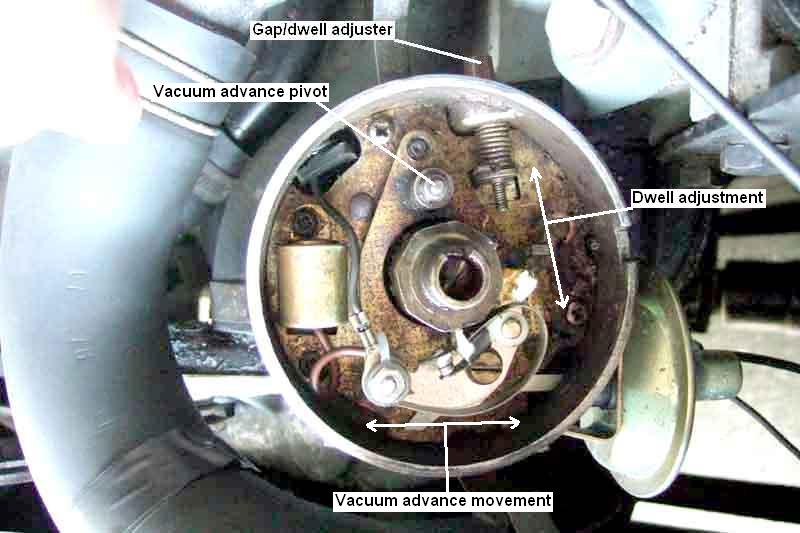 Many features are as above for the 4-cylinder but there are some significant differences. Firstly the points attach to the points plate in a fixed position, not adjustable as in 4-cylinder distributors. The coil and condenser wires attach as for the 25D 'fiddle-fit' 4-cylinder points. Grease the cam lobes (not the felt pad, and not oil) as for 4-cylinder 45D 'quick-fit' points.
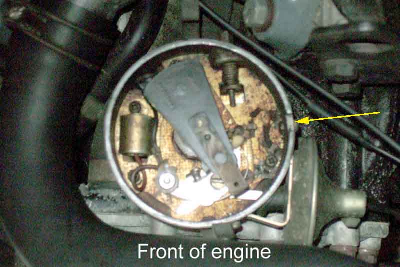 The distributor shaft is fitted with a skew gear as well as a drive dog on the end. The skew gear engages with the end of the camshaft, so can be fitted in as many positions as there are starts in the skew gear. Therefore unlike the 4-cylinder distributor, which can only go back in the correct position no matter how the distributor and crankshaft have been turned while the distributor has been removed, on the V8 you will almost certainly lose the original position if the distributor is removed. To regain the correct position: