


Contents
Index
So you think you want an MGB or V8?
Body
Brakes
Clutch
Cooling
Electrics
Engine
Fuel
Gearbox
Heater
Ignition
Propshaft
Rear axle
Steering and Suspension
Wheels and Tyres
Miscellaneous
Downloadable PDFs
The sectioned MGB at the British Motor Museum, Gaydon
Ignition System
|
Lucas write in their Fault Diagnosis Service Manual that "the standard ignition system will quite adequately meet the requirements of a six-cylinder engine at 8000 rpm". You need look no further than the V8 for verification of that which is firing the coil at double the rate of the 4-cylinder i.e. half the coil recharge time so at the red line of 5200rpm (which it very easily revs beyond) it is equivalent to 10400 rpm on the 4-cylinder. So dwell or points closed time on the 4-cylinder is not at all critical and things like dual-point distributors are double the adjustment trouble plus hotter coils for no gain.
Factory Systems
Fixed vs Variable Dwell
After-market Systems
Problems with After-market Systems and the earlier RVI Tach
Coil Current
Programmable
Fault Diagnosis
Factory Systems
From mid-1974 (i.e. all rubber bumper) North American cars had either the 45DE4 'Opus' electronic ignition (see here for info on the Opus as fitted to Jaguar V12, Aston Martin V8 and Cosworth V8) or the 45DM4 CEI electronic ignition with remote amplifier. They were necessary to meet the emissions requirements of the day, giving consistent results over many thousands of miles (I recall cars of the era having to travel 50k miles with no maintenance other than things like fluids, and having to be in spec at the end), unlike points which deteriorate over distance due to mechanical wear. But with good parts and correct initial setup I find that points easily last 6k to 10k miles without drifting out of the limits for dwell and hence no readjustment (my last 45D4 with their +-5 degrees tolerance for dwell lasted 15k).
The 45DE4 Opus system was very troublesome (it was nick-named 'Opeless') and often replaced with the 45DM4 under the original warranty, I find it amazing that there still seem to be a small number of Opus systems in existence! This Lucas Fault Diagnosis Manual contains some faulting information for the Opus system, but it seems to be for a version that had a separate pickup and amplifier and a different ballast arrangement so may not be that much use. Both factory systems use a (nominally) 6v coil with harness ballast the same as the points operated system on rubber bumper cars for other markets. The Opus system has an additional ballast resistor for the electronic ignition module. Neither of these systems are 'electronic ignition' in the sense of giving a more powerful spark, they are simply 'electronic trigger' systems where the mechanical points are replaced by a magnetic or optical trigger controlling an amplifier, which switches the current in the coil much as mechanical points do. The Opus system has a fixed dwell (unlike the later 45DM4 CEI system) although I believe it is higher than points dwell as it was designed for higher-revving V8 and all V12 engines to give a satisfactory coil recharge time at peak revs, as well as no contact bounce. This has the side-effect that it will cause the coil to run hotter than if points had been used, but as it was only ever used with the 6v coil and external ballast these will still run cooler than a 12v coil with points ignition. See here for information on coil temperature
The 45DM4 CEI system uses more sophisticated electronics in an external module to give 'variable dwell' and did not use the usual rubber bumper ballasted wiring arrangement. The 45DM4 system was used by a large number of manufacturers, albeit with differing physical installation, and the MGB system has been said in the past to be a Delco D1906. At the time of writing the modules may still be available from various sources in China, Google 'DM 1906'. If yours is different physically you can check the other Delco items and other manufacturers e.g. Lucas to see if you can find it. An alternative is NAPA TP45SB (March 2010: Google can't seem to find NAPA) but there has been a suggestion that the 'TP' in the NAPA number denotes Transpo as a source, check the prices of each. However if the fault is in the pickup you have bigger problems replacing it, and you wouldn't want to splash out on a new module only to find it made no difference (see below). Update March 2010: Motaclan/Leacy are showing the AB14 amplifier module (i.e. the DM1906 in a case and with the required leads) as part number BAU1922, at a price of �117, and a 45DM4 distributor for a 1980 California MGB at the same price.
A comparison of points (fixed dwell) and variable dwell electronic systems:
| |
| mS
| 1000 | 20 | 17 | 9 | 1000 | 500 | 7.5
| 2000 | 10 | 9 | 4.5 | 2000 | 1000 | 6
| 4000 | 5 | 4.3 | 2.3 | 4000 | 2000 | 5
| 6000 | 3.4 | 2.9 | 1.5 | 6000 | 3000 | 4
| 8000 | 2.5 | 2.1 | 1.1 | 8000 | 4000 | 3
| 10000 | 2 | 1.7 | 0.9 | 10000 | 5000 | 2.3
| | |||||||||||||||||
Or to put it another way:
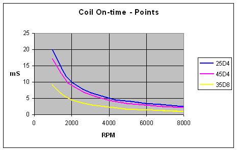
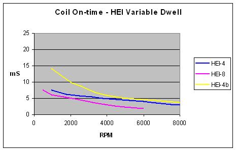
On the left are the three points distributors used in the 4-cylinder and V8 MGBs. On the right is the chip that is used in the HEI system of the 45DM4 MGB distributor (and many commercial variable-dwell ignition systems, HEI-4) and if the same chip were used on the V8 (HEI-8). These are 'typical' coil-on figures from the manufacturers spec, but the maximum can be as high as indicated in HEI-4b i.e. significantly higher at lower rpms, and approaching that of points.
Fixed vs Variable Dwell: What is not so obvious from those graphs is that variable dwell delivers a short dwell i.e. coil 'on' time at idle which reduces coil temperature, increasing as the revs increase until at peak revs the dwell is higher than fixed-dwell systems to deliver a stronger spark than fixed dwell.
Points, the original factory 45DE4 electronic system and many after-market electronic replacements use 'fixed dwell' whilst the factory 45DM4 CEI system and various after-market systems use 'variable dwell'. With fixed dwell the relative durations of current flowing and not flowing through the coil are fixed regardless of rpm - about 60% flowing and 40% not flowing which equates to about 30 mS at idle down to 3 ms at 6000 rpm. This is much longer than is needed to 'charge' the coil and get a good spark for the whole of the rev range on a 4-cylinder, and generates waste heat, which is constant regardless of rpm. At very high rpms in excess of 10k the reducing current flow time can start to degrade the HT energy, but this degradation is utterly irrelevant to 4-cylinder MGBs bearing mind the V8 engine has half the coil charge time of a 4-cylinder (twice as many HT pulses per revolution) and is still pulling like a train when it reaches the red line.
By contrast variable dwell varies the relative durations of current flowing and not flowing as the rpm changes, flowing for just long enough - around 5 mS - to fully charge the coil at any rpm, so at low rpm particularly idle the coil runs much cooler. However the difference decreases as the revs increase, and at maximum revs the energising time in variable dwell systems becomes higher than points - at 6000 rpm a 4-cylinder coil is energised for about 4 mS.
Geoff's 77 has an under-cap after-market electronic ignition system. Fitted by the people he bought the car from so he didn't know what type, and I didn't want to disturb things to have a look when I didn't need to so used my volt/dwell meter. Voltage tests showed it to be the type that didn't pass current through the coil until you start cranking, and dwell meter showed it is a variable dwell system, this clearly showing the dwell increasing as the revs are increased:
When installing components under the distributor cap make sure fixing screws are not too long or they can foul the weights and cause a misfire.
From Roger Parker on the MGOC forum in February 2018:
The Lucas Fault Diagnosis Manual states "the standard ignition system will quite adequately meet the requirements of a six-cylinder engine up to about 8000 rpm". The following table compares the coil on-times between the 4-cylinder 25D4 and 45D4, V8 35D8 points systems and GM HEI variable dwell systems - that module being the core of the factory 45DM4 system as well as many after-market systems.
These figures also show that a dual-point distributor is just adding complexity for no gain - other than a higher temperature coil - as the additional coil on-time simply isn't needed for a good spark at any rpms likely to be found on an MGB engine. And if you think about it its USP is exactly the opposite of a variable dwell system - they can't both be 'right'!
But if you are determined to replace your points distributor, read on. Aftermarket devices such as the Pertronix Ignitor and Lumenition Magnetronic are similar to the factory systems in that they are electronic triggers and replace the points, and with modern electronics they can be made small enough to fit entirely inside the distributor cap. Lumenition Optronic seems to be much the same except it uses an optical trigger instead of the magnetic of the Magnetronic and requires an external power module. All these systems are the same as points in that they are Inductive Discharge systems, using a 'switch' to break the circuit through the coil and generate the spark. I see claims from the manufacturers that they deliver double the coil voltage and four times the spark energy, but personally I don't see how. They are just a switch, turning coil current on and off, just like points. Spark energy is controlled by coil design and the current flowing through it, so the only way such claims can be accurate is by comparing it with very badly degraded points. Also electronic switches pass LESS current than a decent set of points, which is why the factory used higher energy coils with their electronic systems. On the other hand the cheaper fixed-dwell systems show a higher measured dwell than points, which will cause coils to run hotter.
Electronic systems popular in the 70s like Sparkrite were Capacitive Discharge which used an oscillator to charge a capacitor to a high voltage, then discharged the capacitor into the coil to generate the spark. This results in a high voltage at the coil LT terminals, and a dangerously high voltage at the HT terminals, which if open-circuit i.e. not connected to a spark plug could cause injury up to and including death. Whether these much higher energy systems result in anything useful is debatable. IMHO they may make the difference between starting and not starting under the most adverse conditions of weather and poor maintenance, or consistent firing of the much weaker mixtures used in modern engines.
November 2021:
 If you have vacuum advance that is continually twisting the 'points' plate back and fore as you alter the throttle. The 25D4 distributor has cloth-braided tinsel conductor wires for the coil and earth wires which are very flexible to cope with this twisting. The 45D4 has a more conventional wire from the condenser leading out of the distributor body to the coil wire but it has more and thinner conductors than the one it connects to, plus a similar earth wire as before, to do the same job. Under-cap systems such as Magnetronic have two wires coming out of the distributor in the same space as the one points wire, and Optronic has three. Whether these are as flexible as the factory wires I don't know, but Ben Columb has had a long-standing intermittent hesitation problem for many months if not years. He'd done all sorts with timing and carbs to no avail, and eventually said the tach was doing strange things at the same time, to which I and others said 'ignition LT'. Eventually he tracked it down to broken conductor strands inside the insulation of one of the Optronic wires, which means a replacement trigger unit at �110, as opposed to a 45D4 condenser at under �10.
Often after-market systems cause problems for the electronic tachometer, particularly with the earlier RVI current-triggered type (see here for some suggestions on resolving this). Positive earth cars need to be treated differently as described here. Other down-sides are that when they fail they often do so suddenly and totally, they are difficult or impossible to diagnose or repair other than by substitution, and expensive to replace (see above). By comparison points and condenser are cheap to carry as spares, and easy to diagnose and replace at the roadside. Updated July 2010: A while ago a very much cheaper version of the 'under cap' electronic module from Simon's Best British Classics came to my attention. At around �20 these are about a third or less than the price of the Pertronix, Aldon and Magnetronic versions so it becomes feasible to fit one and carry another as a spare. However on the MG Enthusiasts BBS some people swear by them, and others swear at them after repeat failures. One of these people had two Pertronix fail, another had external unit types fail. Yet another had two from SimonBBC fail, but these were blue (like David Blake's junked item below) whereas current stock appears to be red. However the descriptions for the various types are a bit confusing. Some for the 25D4 say they are for 12v coils and no external ballast, which they all were from the factory anyway, whereas some for the 45D4, which were all ballasted from the factory, don't mention this. And at least one says if used on a ballasted coil it will be damaged, similarly if jump-starting from another car! In various places it says 12v coils must be fitted and the ballast bypassed, but not everywhere. I've contacted the vendor and he informs me that as long as the red wire is taken to a 12v supply, for example the white wire at the fusebox on cars with ballasted ignition, then the module will be fine (See here to confirm whether you have a ballasted or a non-ballasted system, which you really need to do if intending to fit one of these units regardless of how your car might have come out of the factory). It's a pity he can't make this clear on the site. If you do replace your 6v coil and ballast with a 12v coil, then you are throwing away some of the benefits of electronic ignition. Original 12v coils have higher reluctance, which means they need a longer coil recharge time for a given HT spark than 6v coils with a ballast, so you are getting a weaker spark at peak revs. A 12v coil will also run hotter than a 6v coil, unless the ignition module has variable dwell.
The other issue concerns 45D4 distributors, which had two different types of points (and hence points mounting plates) - one sliding (with a pin) and the other non-sliding (no pin). Other vendors supply two different modules depending on the points type, but not this site. Again information from the vendor is that the module is really intended for the non-sliding type, but can be fitted to the other type "if the pin is bent out of the way". Updated November 2010: There is a warning on the site concerning jump starting, recommending that the flat battery is charged either from the other vehicle (or a charger) then the jump-leads removed before attempting to start the car, or the ignition module can be destroyed. This is quite different to the usual jump-start instructions and could take some considerable time to charge the battery enough to start the car. The page also indicates that the unit is not protected against reverse connection, and voltages over 14.2v may damage the module. However the MGB Workshop Manual states that voltages can be as high as 14.7v for an alternator and 15.5v for a dynamo. In the case of the dynamo the voltage regulator is temperature dependant, output voltage increasing as ambient temperature falls, and that 15.5v is at 50F/10C. As temps even in the UK can get quite a bit below that system voltages could be even higher. The instructions also state that the unit cannot be used with a ballasted system - the ballast must be bypassed. One of the suggested ways of doing this is to run a 12v ignition wire direct to the coil +ve, but if you do that without changing the coil to a 12v type the coil will overheat in use. All-in-all quite a few points against use of the system, for all it's cheapness.
Added December 2007: One of the more informative and educational postings to Youtube comparing Pertronix, points and 123. It shows the Pertronix jittering almost as much as points, although that could well be a factor of different amounts of wear on the two old distributors as compared to the new 123, I would have preferred to see the Pertronix and points on the same mechanically refurbished distributor. After replacing the timing chain and gears (obviously not a factor on this distributor machine) on my V8 noticeable jitter beforehand had almost completely disappeared, and that on a distributor with at least 100k on the clock and probably nearer 200k. Note the Pertronix distributor seems to 'advance' in the opposite direction to the points and 123, and the very obvious steps in advance of the 123 as well as its total lack of jitter at higher rpms, although it seems to have significant erratic jitter at lower.
Unfortunately the original 123, despite being a beautifully engineered bit of kit, is designed to a fundamentally flawed concept, and very expensive at �300. The only useful bits on it are the fact that you get a new body i.e. bearings, and a solid-state trigger. But you can get those elsewhere for �45. It's a waste of all that modern technology to simply reproduce the original curves, which were all that could be obtained with the technology available 60 years ago, can only give a rapid increase in advance initially then a slower increase, and at best were only ever an approximation of what the engine really needed. With modern fuels, engines this old and many with modifications, the original curves are even less relevant. One vendor said that he recommended the generic version over the MGB-specific (that were available at the time) as the curves were 'better' for today. Another vendor has said that the curves don't match the specifications anyway, and it needs setting-up on a rolling-road (which he happens to have ...) to get the best out of it! It's like someone designing a new engine with the latest mechanical, ignition and fuelling technologies, but configuring it to deliver 110 ft.lb and 63BHP at 3000rpm, and 27mpg, and charging double the price of a rebuilt original! Far better are programmable systems where you can set the advance rev point by rev point for your specific engine and fuel and store a number of maps, one of which when combined with a new distributor body and electronic trigger is only half the price of the 123. Subsequently a programmable 123/Tune was produced.
August 2019: I have recently discovered that the 123 relatively easily if required, for example if the timing gears or drive gear have been installed incorrectly. Incidentally the same can be done on conventional distributors but can need significant force to drive the roll-pin out. Only an aesthetic nicety really, the original error is still there, and the same thing can be achieved by moving the leads round on the cap by two positions to suit where the rotor points.
September 2020: Brian Wall has contacted me to say that after installing a 123 non-tune version with the curve recommended by the MGOC and following the instructions exactly:
Added January 2008, updated October 2008:
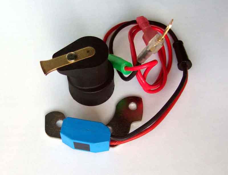 Dave Blake had purchased a distributor on eBay that seems to have been a standard 45D4 but with an electronic trigger (seen here) instead of points. He recounted on the BBS considerable problems trying to get his engine to work properly, eventually resolved when I suggested replacing the trigger with points and a condenser! Dave was going to bin the trigger but kindly sent it to me instead. It is of the same type as Pertronix/Aldon/Magnetronic i.e. magnetic and contained entirely under the cap, but is of a different unspecified manufacture, I tried to find out what without success, but subsequently info from Gary Falkiner indicates that it is also used in a Land Rover conversion kit. It has the same two wires leading out to the coil as the others i.e. one red to the coil +ve and one black to the coil -ve, but the rotor is different on both Dave's and Gary's in that the magnets are integral, the others have a separate magnetic ring that fits over the cam, then a standard rotor goes on the end of the shaft as normal. The separate magnetic ring definitely preferable, as with this integral unit if the rotor should need replacing you would have to get this special one with the magnets, and without knowing the manufacturer whether you would be able to obtain one from eBay is anyone's guess. The alternative would be to scrap the unit and go back to points ... I put Dave's on my bench tester and found that it triggers 30 degrees before points in the same distributor. Whilst this variation could be compensated for from a timing point of view fairly easily by simply twisting the distributor in the clamp, one is left with a change in phasing i.e. the relative positions of rotor and cap contact when the trigger fires. And on my test distributor with a cut-away side I could see that when you start to add vacuum advance, the rotor was moving away from its cap contact, so the spark was having to jump a larger and larger gap. Eventually it would fail to do so, or jump elsewhere, causing erratic HT and misfire when fitted to an engine. Why it is like this is anyone's guess - poor manufacture? Wrong rotor? Who knows? Dave was fortunate in that he was able to retro-fit points and a condenser, it could have had a trigger plate that wasn't compatible. Gary reported that he had to retard the timing by 15 degrees to get back to the same point as before, showing that his phasing was also significantly different to points. Initially it seemed to run well but after a bit of use it was noticeably inconsistent, and kept picking up iron filings on the magnetic collar which may have been affecting things. In the end he went back to points as well!
Added February 2008:
Another problem that has just come to light when replacing points with one of the 'under cap' systems concerns the condenser fixing screw. As part of installation you remove the condenser as it is no longer required, but the screw has to be refitted to secure the braided earth wire which is still needed with these 'under cap' systems. After installation the engine was run but was giving very poor and erratic results. Eventually the cause was found to be the condenser fixing screw was too long and being hit by the centrifugal advance mechanism. Probably a non-standard screw in this case, but something else to be aware of.
Coil Current: Many moons ago someone, rather smugly I thought, said electronic triggers are better than points as they have zero 'contact' resistance i.e. better than points even if they (the points) only dropped a tenth of a volt. At the time I wondered if he had ever measured the volt-drop across an electronic trigger, because one of the many things I remember from my electronics theory days is that semi-conductors exhibit a forward-bias volt-drop when conducting. This doesn't vary with current as in a conventional resistor, but instead differs according to the semi-conductor junction material. I remembered this as 0.3v for germanium diodes and 0.7v for silicon, pleasingly repeated here. However those are diodes, the switching in these devices will be done by some kind of transistor. Again from my theory days 'Darlington pair' transistors are used to increase switching current capability, and we are talking about 5 to 6 amps for an ignition coil. These have twice the base to emitter volt-drop than single transistors as there are two in series, but there are two parallel paths from the source voltage to the load. Whilst this will double the current that the trigger can safely handle the volt-drop will remain the same as each path is still dropping the same voltage even though the current has halved - Ohm's Law does not apply.
Some systems say they use Hall-Effect devices, which potentially (!) confuses the issue. A Hall Effect device senses a magnetic field and essentially controls a flow of current like a switch. But as they can only handle about 40mA these devices must be in the sensor where there are magnets rotating with the distributor shaft. Other systems use an LED and a photo-cell with a rotating blade like a propeller between them and both types generate an output pulse at the required time. Both are only controlling other electronic components in the modules and it is those components that are doing the actual switching of the the current through the coil, and are almost certainly the more usual silicone devices above.
Being a simple chap and far more reliant on practice than theory, there was nothing for it but to measure it - and the results were very interesting. A set of old points, used as removed i.e. the contact faces not cleaned up, gave about 0.5v, so quite a bit. But the electronic trigger (magnetic) gave fully 1v! I also noticed it is a fixed-dwell device just like points, and not variable dwell like the 45DM4 or some after-market triggers. These Reopus FAQs indicates that the original Opus system also gave a 1v drop, and when the MGB changed to the ballasted ignition and 6v coil in rubber bumper cars, and North America got electronic ignition, the UK cars got a coil with nominally 1.5 ohms primary resistance (16C6) whereas North American coils were nominally 1.4 ohms (15C6) precisely so as to offset this reduction in voltage and current. Very late in production in 1980 North American coils were changed again to a 32C5 for which several sources give a nominal primary resistance of 0.8 ohms! By this time they had the 45DM4 distributor and electronic ignition system, it would be interesting to find the volt-drop in these, as well as other electronic triggers such as Pertronix and Aldon Igniters, and Lumenition Magnetronic.
April 2024: As part of a thread involving possible ignition problems the following fault diagnosis information from Aldon about their electronic ignition system was given:
- Remove the King Lead from the Distributor and Earth to a Cylinder Head Bolt
- Set Volts on Multimeter to 20v Scale
- Red Probe of a Multimeter on the Coil - (Negative)
- Black Probe of Multimeter on the cars earth
- If meter shows "0" Volts Trigger Unit Is Open Circuit
- If Meter shows "1-3v" Module Faulty
- If you get either of the above readings the Trigger Module has failed and a replace is required
- If you get a constant Battery Voltage (12v+) check the wiring and connections of the module to coil.
- If You have None of the above proceed to crank the engine and the Multimeter should read between 1.5v to 12v which indicates the Trigger Module is Switching the Coil Correctly
- Point 9 is the critical thing in determining whether points or electronic ignition give a 'better' HT spark. In an ideal world there would be 0v on the coil -ve with the points or electronic trigger closed and passing current, as that would put the full system voltage across the coil, and hence drive the greatest possible current through it, create the greatest magnetic flux, and hence generate the greatest spark when the points or trigger opened. By saying the multimeter should read between 1.5v and 12v shows that 1.5v is being 'lost' inside the trigger module when it is passing current which reduces the voltage across the coil, hence a lower current, lower magnetic flux, and a lesser HT spark. With a system voltage of 12v across a 3 ohm coil then 4 amps would flow. But if there is only 10.5v across the coil (12v minus 1.5v) then only 3.5 amps will flow. This is why when the factory fitted electronic systems to the MGB they used a lower resistance coil which increased the current and hence the magnetic flux and the spark compensating for the reduced coil current.
A secondary aspect is that usually in a running engine with a working charging system the system voltage is typically 14v not 12v.
- Point 5 indicates that with the meter connected between the coil -ve and a body earth if you see 0v then the trigger unit is open-circuit. The trigger unit is also connected between the coil -ve and earth and so to see 0v the trigger unit would have to be short-circuit, not open-circuit. However you would also see 0v on the coil -ve if the coil itself were open-circuit or the 12v supply to the coil +ve was missing.
The points volt-drop of 0.5v above was measured on a bench test rig with old points so I thought I'd check the V8 with relatively new points, and I was a bit surprised to see almost as much at just under 0.4v, so I decided to dig in a bit further. I was measuring the voltage between the two most accessible points, which was the -ve coil stud and the distributor body. But this includes the points wire spade to coil tag, points wire, connection to points, points themselves, points base to points plate, distributor earth wire, and its connections to the points plate and distributor body. When I started breaking these down the results got very interesting indeed:
| coil stud to points wire spade | 0.03v |
| points wire, coil to points | 0.19v |
| points wire terminal to points spring | 0.03v |
| points | 0.08v |
| points base to distributor body i.e. distributor earth wire | 0.02v |
Programmable: December 2013 Fairly new to the market are two programmable modules that are inserted between the trigger and the coil - Aldon Amethyst and Accuspark Stealth. A pal has some experience of the former but from the blurb they seem to be similar in that that allow you to develop your own set of curves by specifying the amount of advance at a number of rev points. However it looks like that Amethyst manages the vacuum advance - and boost retard if you have a supercharger - and hence is also mappable, whereas with Stealth vacuum advance remains as before i.e. is fixed by the distributor vacuum capsule. Another difference is that whereas Amethyst is compatible with points or any electronic ignition module, the Stealth information implies that you must have an under-cap electronic trigger. See also this from the Amethyst designer, who did the initial development on a 1967 MGB.
Said pal put an Amethyst on his supercharged MGB and tinkered with the rev points increasing/reducing until he ended up with a 'curve' whereby each rev point was one degree short of causing pinking. He ended up with a very unusual (by mechanical distributor standards) curve, but the whole point of being able to configure your own is that it can be tailored to exactly what your engine and fuel grade require right across the rev range. By comparison a conventional distributor is a relatively crude device, pretty-much only able to have a steeper increase at lower rpms, and a shallower one at higher. The upshot was a noticeably faster car using the 'seat-o-pants' meter.
Subsequently the 123 was upgraded to a programmable version, but it is an 'all or nothing' device in that if fails you are stuffed. If the Aldon or Accuspark modules fail you can bypass them and run the coil directly off your trigger. Both Amethyst and Stealth require you to disable the centrifugal advance on the distributor so bypassing the modules prevents any additional centrifugal advance, which would reduce performance and economy and increase running temperature, but at least it would allow you a 'limp home' mode. Amethyst installation instructions say to set the distributor to your normal static advance, whereas the Stealth instructions imply that you set it to TDC which would hit performance and economy and increase running temperatures even more. However I don't really see why the distributor with Stealth couldn't be set to the static figure just like Amethyst. Bypassing Amethyst would disable vacuum advance as well, but that can be dealt with by simply transferring the vacuum pipe back to the distributor capsule. At the time of writing the 123 is very expensive at �300, the Amethyst significantly cheaper at �200, and the Stealth half the price of the Amethyst at �100, but you have to add the cost of an electronic trigger to the Stealth. Incidentally Accuspark claim "Electronically adjust intial (sic) timing by up to 9 degrees via laptop, no need to adjust distributor with timing light" but this is incorrect, or at the very least misleading. With both these modules you can only set the additional advance with a computer, not the absolute figure. You still have to position the distributor in the block to give the correct initial advance - either to the static figure or to TDC, which can only be done in the normal way i.e. statically with a test-lamp or meter, or dynamically with a timing light.
Fault Diagnosis October 2015
Misfiring
Cranks but won't start
Weak spark?
Cutting-out - either momentarily i.e. similar to a misfire, or stopping the engine altogether:
If the tach does suddenly drop to zero then look at the ignition warning light (if it has been working normally that is!) as well. If that is glowing then you have lost the voltage supply to the ignition system. In most cases this means a fault in the ignition switch or its wiring, but on 1977 and later cars with ignition relay it can also be caused by the ignition relay and it's wiring.
If the ignition warning light is not glowing, try another ignition powered circuit such as the indicators - you will probably want to be indicating to pull over anyway! If they don't work either, then it's probably going to be a break in the wiring between the ignition switch or relay and the fusebox.
Due to changes over the years and markets the indications of the ignition warning light and indicators can point to different causes, I've tried to summarise these below:
| Year/market | Warning light | Indicators | Likely area |
| 62-64 | on | (no) | brown to ignition switch, ignition switch |
| off | no | white from ignition switch to fusebox | |
| off | yes | white from fusebox to coil etc. | |
| 64-67 Mk1 | on | (no) | brown to ignition switch, ignition switch |
| off | (yes) | white from ignition switch via tach to coil etc. | |
| Mk2 67-72 UK | on | (no) | brown to ignition switch, ignition switch |
| off | (yes) | white from ignition switch via tach to coil etc. | |
| Mk2 67-72 NA | on | (no) | brown via bullet connector to ignition switch, white to bullet connector |
| off | (yes) | white from bullet connector via tach to coil etc. | |
| 73-74 UK | on | (no) | brown to ignition switch, ignition switch |
| off | no | white from ignition switch via bulkhead 4-way bullet connector to fusebox | |
| off | yes | white from fusebox to coil etc. | |
| 73 NA | on | (no) | brown via bullet connector to ignition switch, ignition switch, white from ignition switch to bullet connector |
| off | no | white from ignition switch bullet connector via bulkhead bullet connector to fusebox | |
| off | yes | white from fusebox to coil etc. | |
| 74 NA | on | (no) | brown via ignition switch multi-plug, ignition switch, white via ignition switch multi-plug |
| off | no | white from ignition switch multi-plug via bulkhead bullet connector to fusebox | |
| off | yes | white from fusebox to coil etc. | |
| 74½-76 UK | on | (no) | brown to ignition switch, ignition switch |
| off | no | white from ignition switch via bulkhead 4-way bullet connector to fusebox | |
| off | yes | white from fusebox to coil etc. | |
| on | (no) | brown via ignition switch multi-plug, ignition switch, white via ignition switch multi-plug | |
| off | no | white from ignition switch multi-plug to fusebox | |
| off | yes | white from fusebox to ignition ballast etc. | |
| 77 UK | on | (no) | brown via ignition switch multi-plug, ignition switch, white via ignition switch multi-plug to ignition relay, ignition relay, white/brown ignition relay to fusebox |
| off | no | fusebox white/brown connections | |
| off | yes | fusebox to ignition ballast etc. | |
| on | (no) | brown via ignition switch multi-plug, ignition switch, white to ignition switch multi-plug | |
| off | no | white from ignition switch multi-plug to ignition relay, ignition relay, ignition relay white/brown to fusebox | |
| off | yes | white/brown from fusebox to ignition ballast etc. | |
| 78-on UK | on | (no) | brown via ignition switch multi-plug, ignition switch, white via ignition switch multi-plug to ignition relay |
| off | (yes) | white/brown from ignition relay to ignition ballast etc. |
Click on the year and market for the relevant schematic.
Where the 'Indicators' condition is shown in brackets i.e. as (no) or (yes) it means that given the 'Warning light' condition it should always be this way, unless you have more than one fault.
'Coil etc.' and 'ignition ballast etc.' refer to the remainder of the ignition LT circuit i.e. through the ignition ballast (where provided), coil and points or electronic trigger to earth. Where the ignition warning light is extinguished and the indicators etc. still work the problem will lie in this part of the system. As well as disconnections in the wiring between fusebox, ignition ballast, coil and distributor, systems with points and after-market under-cap triggers rely on an earth wire inside the distributor that connects the points or trigger plate to the distributor body. With vacuum advance the points plate is continually being twisted back and fore as you change the throttle position, and this earth wire as well as the points or trigger wires as they pass through the body of the distributor, can fracture the conductors inside the insulation.
June 2016: Systems with an after-market electronic system where the electronics module is external to the distributor such as Lumenition Optronic use three wires from the trigger to the module and one of these is an earth or 'common' wire, so the original earth wire is no longer used. However any of the three wires can suffer from internal fractures due to the points plate twisting with changing vacuum as with the other systems.
Misfiring: On two occasions now I have heard of an erratic misfire - that may vary with revs - being caused by a fixing screw through the points plate, either for points/electronic trigger or condenser, that was too long. This was being hit by the weights as they spun and opened out which momentarily joggled the points plate and affected the firing position.
Static tests: With points ignition diagnosis of ignition system faults is relatively easy. With electronic ignition it can be more difficult, usually substitution with another system is the only way, but see below. For static tests a digital meter should be satisfactory as well as an analogue.
- Points: With the ignition on and the points closed (they usually are having switched off a running engine, or cranked with no start) you should have voltage on the coil SW or +ve, and close to 0v on the coil CB or -ve, both with respect to earth. On chrome bumper cars you should have 12v on the coil SW or +ve, but rubber bumper cars originally had a ballast resistance in series with the coil and the effect of this is to reduce the ignition voltage at the coil +ve to about half battery voltage - as long as you have the correct 6v coil. If you have a 12v coil in series with a ballast resistance you will see about 8v. If you see other voltages there could be a problem with the coil, the ballast, or the wiring connections back towards the ignition switch or relay. If the ballast has been bypassed and you fit a 6v coil then you will burn the points due to excessive current. See here for more information on ballasted ignition and 6v and 12v coils.
If you have 12v on both LT terminals of the coil then the circuit through the points and distributor earth wire is broken. Test the points spring and moving contact, and if that shows an earth then the wire between the points and the coil is broken. If it shows 12v - and the points are closed - then the earth wire inside the distributor is broken.
If you have voltage on the coil SW or +ve and an earth on the coil CB or -ve, then turn the engine by hand until the points open, or hold the points open by hand. You should then see 12v on both terminals of the coil. If you still see 0v on the coil CB or -ve then remove the wiring from the coil CB or -ve. If that terminal now shows 12v then the wire between the coil and points is shorting to earth, this may be from faulty or incorrectly installed points or a short-circuit condenser. If the coil CB or -ve terminal still shows 0v then the coil itself is open-circuit. Another check is to measure the current passing though the coil, which with ignition on and points closed should be nearly 4 amps.
If all that looks correct the coil should be generating HT sparks. Remove the coil lead from the distributor cap and connect it to a plug laying on the block, then manually flicking the points open and closed should show sparks. If not the coil may be faulty, or possibly the condenser is open-circuit. In this latter case the points will be sparking and spitting excessively, to confirm temporarily connect another condenser between the coil CB or -ve and earth. If this reduces the arcing and spitting and you now get the plug sparking then change the condenser. Check the points gap/dwell is correct.
- Electronic ignition
: These vary in that some basically replicate points in that they will be 'closed' and drawing current through the coil as soon as you turn on the ignition, these should show the same voltages on the coil spades as for points. Others do not start drawing current until you start cranking, so until then you will see battery voltage on both spade terminals of the coil on both CB and RB i.e. both non-ballasted and ballasted. Others may initially pass a current through the coil like points, but if the engine is not started for a period it may cut the current off. With these latter two types not allowing current to flow, or turning it off after a few moments, protects the coil from overheating if the ignition is left on without starting the engine for some time. If you completely disconnect the electronic system from the coil you can simulate points by temporarily connecting a condenser between the coil CB or -ve terminal and earth, and connecting an earth to the CB or -ve terminal to simulate the points being closed, and removing it to simulate the points being open. You should get a spark with the coil lead connected to a test plug laying on the block which will confirm everything else is OK and the electronic ignition is almost certainly the problem.
Cranking tests: These can be done with either a voltmeter or a dwell meter (as said above for the voltmeter an analogue instrument is preferable). A dwell meter display in either degrees or percent (%). For the 25D4 a dwell of 60 degrees equates to 67%. For the 45D4 51 degrees equates to 57%. For the 35D8 of the V8 27 degrees equates to 60%.
- Points: If manually operating the points generates HT sparks from a plug connected to the coil, then crank the engine while monitoring the voltage on the coil CB or -ve, and you should see around 5 volts. With a dwell meter you should see about the correct dwell reading if the points gap is correct. On the coil SW or +ve you should see about 10v on all cars but it depends on having a fully charged battery and on rubber bumper cars a working ballast bypass circuit. If you see less than that on a rubber bumper car and battery condition is good the coil boost circuit is probably faulty, although this by itself shouldn't be enough to prevent the engine from starting unless other aspects are poor. However you will need either an analogue meter to see these voltages, or an averaging digital instrument, other digital instruments may have the reading flicking all over the place.
- Electronic ignition: This depends on whether it is a fixed-dwell system like points or variable dwell. With fixed dwell you should see the same as points but dwell can be a little higher and voltage a little lower. With variable dwell you should get a noticeably higher voltage on the coil CB or -ve - between 5v and 10v - but a lower dwell - probably half or less, but it depends on the system. If you see cranking voltage i.e. nominally 10v or a dwell of zero then the trigger is failing to draw current through the coil, which can be confirmed with an ammeter. If you see 0v or 100% dwell, or very nearly so, then the system is drawing current through the coil continuously, which again can be confirmed with an ammeter.
When you have HT at the coil lead then reconnect it to the distributor and refit the cap. Try cranking again, this time with each plug led in turn connected to a plug laying on the block. If none of them spark then the distributor rotor, or possibly the cap is breaking down. If some do and some don't then again it could be the cap, or individual plug leads breaking down, or faulty plugs, swapping plugs between leads should show which. An alternative is to use a timing light and watch the flashes, although bear in mind that a 12v light with inductive pickup may need a separate power supply to work correctly while cranking.
Weak spark? You can use a spark tester connected in series with plug leads or coil lead. There are basic go/no go devices such as the Sealey VS526 (you don't need four of them as in the Laser 2780). However this type only needs to be touched onto the outside of the HT lead so easy to move from lead to lead. If you are going to buy one you would be better off with the Laser adjustable 5655 at a few quid more which allows you to introduce an additional adjustable gap to see just how far the spark will jump, but if you are lucky you might find a Gunson's Flashtest on eBay for a lot less. You should get at least 1/4", higher with a 'sport' coil, much less indicates weak sparking.
You can confirm coil current with a multi-meter. Static coil current should be about 4 amps on both CB 12v and RB ballasted systems. Measure this with the points closed i.e. by inserting the meter between one of the wires and its spade, or by measuring the voltage across the coil and points. Static voltage should be 12v on a CB 12v system, and about 6v on an RB ballasted system. If you see less than that, then measure the voltage between the distributor terminal on the coil and earth when the points are closed. Ideally you would see zero volts, but with 4 amps flowing some voltage drop will occur even in that short wire, the points, and the distributor earth wire. If you see more than a few tenths of a volt then you need to test further to see where it is occurring, i.e. from the points moving contact to earth, and the points fixed contact to earth. If the points are dirty you will see more voltage at the moving contact than at the fixed contact, but you could have losses in more than one place.
See here to test the condenser.
Timing: If all plugs and leads are sparking, then check the static timing. Note this is easy with points, electronic systems may vary and may not be possible. You well have to twist the distributor until you get it running then dynamically time it with a strobe light. 123 distributors seem to have an LED to indicate TDC. Setting this to about 10 degrees Before Top Dead Centre should be enough to start any MGB engine. With the ignition on connect a voltmeter between the coil CB or -ve, and with plugs out turn the engine until the notch on the crank pulley is under the 10 degree pointer on the timing cover. The last pointer the notch passes should be TDC, a smaller pointer immediately before that should be 5 degrees BTDC, and a large pointer immediately before that should be 10 degrees BTDC. With the pulley notch at 10 degrees slacken the distributor clamp bolt or clamp plate bolts and twist the distributor clockwise and anti-clockwise watching the meter switching between 12v and 0v, which is as the points open and close respectively. You should find that as you turn the distributor clockwise the voltage goes to 12v as the points open, and goes to 0v as you turn it anti-clockwise and the points close. If you find it is the other way round then the distributor is 45 degrees out and needs to be turned one way or the other until you get the correct voltage swing. Then with the voltmeter at 0v i.e. points closed, slowly turn the distributor clockwise until the points just open and the voltage goes up to 12v. Tighten the clamp plate bolts - but don't overtighten the bolt on the plate that clamps the distributor body. Make sure the 4-cylinder distributor body flange is flush with the clamp plate when the clamp plate is fully bolted to the block. This ensures the distributor is fully seated into the drive gear, as it can partially seat when 180 degrees out.
Plug lead orientation: The distributor on the MGB rotates anti-clockwise as you look down on the top of the cap, and the firing order is 1, 3, 4, 2 with the cylinders being counted from the water-pump end to the flywheel end. Start by determining where in the distributor cap No.1 plug lead goes, then count the rest from there. To determine where No.1 goes turn the engine to TDC on the compression stroke of No.1 cylinder, and see where the rotor is pointing. Normally it points to about 2 o'clock, but if the timing gears have been fitted incorrectly, or the distributor shaft has been dismantled and put back together incorrectly the rotor will be 180 degrees out. Also if the 4-cylinder engine distributor drive gear has been inserted to the engine incorrectly the rotor could be in as many positions as there are teeth on the drive gear (eight or nine). The V8 distributor is different in that the drive gear is on the end of the distributor shaft, so more care is needed to refit the V8 distributor to the engine.
It also needs to be borne in mind that on a 4-stroke engine each piston passes through TDC twice for every combustion cycle - once on the compression stroke and once on the exhaust. To set it correctly see here. As long as you fit No.1 plug lead in the cap position that aligns with the rotor position and count the rest from there, the engine should start and run, even if the rotor is not at 2 o'clock. If you want to correct the rotor position then see here.
There is yet another possibility for incorrect timing and that is if the wrong crankshaft pulley has been used, or it is a damped pulley and it has started delaminating - which is where the outer part that carries the timing notch moves in relation to the inner part that is keyed to the crankshaft. To check for this see here.
Even after all that if the engine has been dismantled, reassembled and won't start it could be something fundamental like valve timing or compression.
And my own experiences
Firing order and lead positioning
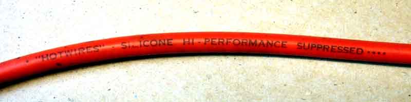 In the UK at least carbon powder-impregnated string was the standard lead for many years covering the 60s and 70s at least, but the carbon powder moves around and the leads can go high resistance causing ignition problems quite quickly. Then silicone-cored were produced which are much more stable lasting for decades in my experience. It's confusing because many sources also call these 'carbon impregnated', and say they don't last very long, but that is simply not the case in my experience. In more recent years leads have become more 'hi-tech' with an insulating core wrapped with many turns of fine metal wire to give the resistive feature, under silicone-rubber outer layers. These are said to offer better interference suppression which can be important for the electronics on modern vehicles. Beyond that some people produce massively thick HT leads, which is OK if you are running very large plug gaps and very high voltage systems (which have issues for conventional distributors and rotors on cars of our era) plus all sorts of fancy features like capacitors and earthing wires. The common factor in these latter types is their humongous price, and the apparent belief in some have that if they cost that much they must be better. For cars of the MGB era and those ignition systems anything other than basic silicone is a waste of money.
There are two basic types of spark plug wires-copper and silicone. The copper wires are great for conducting the high voltage current from the coil to the distributor cap and from the cap to the spark plugs. They have a They have a long life and seldom need replacement. When they do, it is normally due to the insulation of the wire breaking down and causing some of the high voltage to leak. In most cases, they will still conduct electricity, but at a reduced voltage. There is only one real problem with copper wires-they create a minor radio transmitter and produce electrical interference with TVs and radios.
To correct this problem, silicone wires were introduced. These wires have some degree of internal resistance which surpasses the radio/TV interference. The silicone wires became more popular back in the late 60s and early 70s as the car producers began to offer more sophisticated radios. FM was becoming popular with the masses as the stations expanded and cassette and eight track tape players became popular. Prior to this time, people with the very expensive (back then) radio systems had to fit resistors to each individual copper wire to suppress radio interference. With the silicone wires, none of this extra suppression was required. The only drawback to the silicone wires was that they wore out. In the early versions, rather quickly. Today, silicone wires, much changed from the earlier versions are the standard. Unfortunately, they still do not last as long as a good set of copper wires and need to be inspected to see if they are functioning properly.
The first step in inspecting the wires (of both types) is to check to see that they are clean. Dirty build up on the exterior of the insulation may allow some of the current to be lost. It can also speed the breakdown of the insulation leading to current leakage. Examine each wire and, if dirty, clean with either waterless hand cleaner or dish washing detergent. Dry and wipe clean before reinstalling. It is best to remove one wire at a time to prevent mixing them up. Most old hands will be able to install the wires on a bare cap and get them in order with no problems. But, we all make the rare mistake and doing one wire at a time will help to keep the mistakes rare.
The next thing to check is that the ends of the wires are firmly attached to the spark plugs, the distributor cap and the coil. Four cylinder, in line engines are not the smoothest running of beasts and, sometimes, a wire will work its way loose. This is especially a problem at the cap, but Bob and Gil found two wires loose at the spark plugs on two different cars when they were helping me a couple of weeks ago. Always check to see that all connections are properly seated.
The next test requires darkness. You need to start the car with the hood open and run it while looking for blue sparks off the wires or a blue glow surrounding them. This indicates the current is leaking through the insulation and the full current is not being carried to the distributor cap and then to the spark plugs. In really bad cases, this can actually light up the right side of the engine compartment. WARNING: It is dangerous to work around the engine compartment in the dark with the motor running. Put your hands in your pockets when performing this inspection and do not take them out until you are ready to turn off the engine. Running the car in the garage will help to cut down the ambient light, but make sure the door is open to prevent the build up of carbon monoxide.
If you see blue sparks, you need to replace the wires with a good quality set of replacement wires. The ones by Robert Bosch seem to fit the B very well and last well. They are available from BAP and other sources. One problem with the silicone wires is that they do not work well with the screw in, side terminal caps on the Mark I cars. This is not a significant problem. If it is a show car, get the copper wires, which were originally correct for this model. If it is not a show car, the 68-74 distributor cap will fit the distributor and allow you to use silicone wires that push into it. You will also need to install a different coil, one with the push in style terminal, but this would be a good time to install a Lucas Sports Coil anyway, right?
If the car seems to be running well, this is all the testing you need to do. If, however, you seem to have a miss, there is one further test you can run. This requires an ohm meter. An ohm meter measures resistance and is normally a feature found on volt meters. In fact, most volt test meters are actually Volt-Ohm Meters (VOMs). Good quality analogue meters may be had for under $20 at Radio Shack and other sources. Some dwell/tach meters also have a volt and ohm feature. I prefer to have a separate VOM as it allows me to do tuning using both the dwell/tach and the VOM when necessary.
The first thing to do is turn on the meter and set it to ohms or resistance function. Then, touch the two probes together and watch to see the meter's needle swings to zero. This shows that there is zero resistance as it should be. Some of the more expensive meters have a zero function where the probes must be held to zero and the scale adjusted to zero. The less expensive models do not have this feature and it is not needed for this type of work. Having confirmed that the meter is working properly, remove the distributor cap from the car, having disconnected the spark plug wires from the plugs and the coil wire from the coil. A small piece of masking tape on each wire with the number of the cylinder the spark plug wire came off of makes reattaching easy.
Then, take one probe and stick it into the spark plug end of the wire. You can probably insert it between the metal terminal and the boot to hold it in place. Then, you touch the probe to the terminal inside the distributor cap. This tests both the cap and the wire. Make a note of the resistance reading, then check the other plug wires in the same manner. Finally, check the coil wire from the end that goes into the coil to the carbon brush in the top, center of the cap. All of the spark plug wires should have about the same resistance. If one is very much lower or higher than the others, the set may need replacing. If one shows infinite resistance, the set may need replacing. How to determine whether it is a wire or a cap problem?
Simple. Remove the wire showing the infinite or high resistance from the cap and measure it again. If it now shows resistance similar to others, it is a problem with the distributor cap. Firmly seat the wire again into the cap, making sure it is fully engaged and check again. If it still shows a problem, the cap is at fault. If, however, when you test the wire by itself, it shows high or infinite resistance, the wire is bad and the set should be replaced. This is where the �lifetime warranty� pays for itself. Take the wires back and exchange them for another set. I go one step further and keep a spare set of wires on hand and, when I need to exchange them, install the spare set and return the old set in the box.
The final question is how long will the silicone wires last. The best examples may do as long as three to four years. Often, however, the Arizona heat and high under hood temperatures will have them breaking down in two years or so. Testing the wires while doing a tune up only takes a short time. Good wires will give better fuel economy, reduce pollution and not leave you stranded when the car does not start. Time well spent.
This article is copyright 2001 by Les Bengtson and may be reproduced for personal use as long as the copyright and authorship is acknowledged. Please direct any questions to: ragnar@aztec.asu.edu.
My own experiences: In 1973 I bought a new Morris Marina, and ran it for six years. That came with original carbon-string leads of course, and after a few years I started getting ignition problems, checked the resistances and they were all over the place. So I bought a set of silicone-cored from Halfords and had no more problems. When I bought the roadster in 1990 the plug leads were a mixture, so I bought a set of silicone again from Halfords. Many years later one day it wouldn't start, and after some time I found it was because the brass connector at the coil end of the king-lead had some kind of blue coating, that I couldn't scrape off, and seemed to be acting as an insulator, so I bought a new set and since then they have been fine.
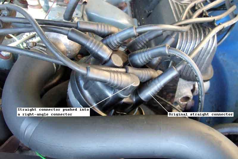 When I got the V8 in 1994 again it had a mixture of leads, I enquired of the MGOC and was surprised to discover they had the original carbon string type, even more surprised to discover they were dearer than the silicone equivalents, and bought the silicone. Try as I might and no matter which way round I connect the leads, the best I can end up with is one on the left bank slightly shorter than really it should be, although it is just about OK taking a direct run at the plug. It does however mean that the leads in the combs are not strictly in the correct order. The other problem is that because the distributor is at the top of the engine, and canted sideways, the leads feeding the right bank run closer to the bonnet than the left bank. The original leads had right-angle connectors on all the right-bank leads which keeps them low enough, but the new ones are all straight, turn back on themselves and are pressed up against the bonnet which I don't like. However amongst my many retained bits I have four right-angle connectors, the leads push into those, and they push onto the cap so all is hunky-dory. And after (currently) 29 years and 100k+ miles they still look and work as good as new.
However in September 2018 someone was asking about resistance of plugs and leads and whether they could be causing a misfire on cold starts, so I did some research into lead resistance. Various Google sources indicated about 6k to 8k per foot, and checking one of Bee's and Vee's longest one out of interest that proved to be the case. But checking Vee's coil lead i.e. the shortest it was 80k! As there is no sign of running problems at the very least it indicates that resistances as high as this are not necessarily going to cause a problem. I do need to replace it, but checking the other leads they are all in the range of 10k to 23k and vary hugely in length so they seem OK. Whilst you can get a set for �17, you can also pay up to �100. But after the problem with one lead being a bit shorter than ideal, and not having the correct right-angle connectors for the right bank, I'm in no rush to change all of them unless I have to, and have had a single lead made to order. In the meantime I've modified the 'old' roadster No.4 lead (8k) which is only slightly shorter than the V8 coil lead and fitted that, and when the new lead arrived I opted to carry the removed V8 lead just in case of problems. Incidentally, I had the new lead made the same as the old i.e. with straight connectors each end. Right-angle connectors were available at no extra cost, and it was only afterwards I realised that not only do they result in a better fit for the coil lead, but looking at various sets for the V8 that seems to be how it should be! Oh well.
V8:
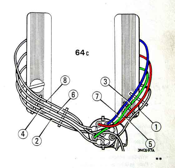 The other thing to be aware of on the V8 is that cylinders 5 and 7 are next to each other in the firing sequence as well as being next to each other on the engine, and at the back so the leads are quite long and run parallel to each other. The factory seems concerned that the firing of 5 could induce enough voltage into lead 7 to initiate premature firing of that cylinder, so show the two leads 5 (red) and 7 (blue) being separated in the combs by lead 3 (green), as shown here.
How do I tell which I have?
Should I have a ballast resistor?
How do I tell if there is one on the car?
Is this a ballast resistor?
Isn't the coil used on rubber bumper cars a 9v coil?
What about a coil with an internal ballast resistor?
Why did they change to 6v coils anyway?
Testing a coil
Rubber Bumper 'Coil Boost' System August 2014:
Should I reverse the coil connections when changing the car's polarity?
What is an oil-filled coil?
Should the coil point up or down?
Is my coil too hot? Added January 2013
 All frequent questions as part of a lot of confusion on this subject. Coil manufacturers don't help - I have come across two coils marked '12v' but also saying it needed an external ballast resistor! This is confusing if not incorrect, and some suppliers do have completely incorrect information on their web pages. You won't know what you have got until you measure both the wiring and the coil, and that goes for newly purchased coils.
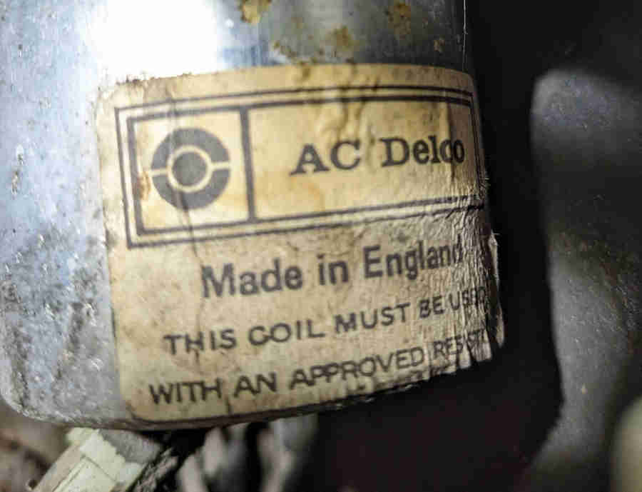
There is lot of conflicting and confusing information on the web regarding coil and ballast resistances. Haynes and Clausager differ in some respects, and even the Leyland Parts catalogue for September 76 on i.e. ballasted ignition isn't immune as it specifies GCL110 for other than cold climates and the USA, but every other source I have seen says that is a 12v coil i.e. for unballasted i.e. chrome bumper cars. One example of a coil marked '12v' and 'must be used with an approved resistance' measured 2.2 ohms which is too high for a 6v coil, but also too low to run on an unballasted system as it will overheat. Hence the label saying it must be used with an approved resistor, but that can only be one measuring 0.3 ohms at most or it will degrade the spark. One MGOC advert states "Ballast Ignition Coil 12 Volt - GCL111 - DLB111 Ballast ignition coil, 12 volts, 3 ohm. Rubber bumper only." which is completely incorrect. The distinction between the three original types of 6v coil seems to have been lost as far as replacements are concerned. Some sources specify a GCL132 coil for ballasted systems but others say this is a 9v coil and not a 6v. I've not been able to find a resistance quoted for this coil, but the implication is that using a 9v coil on a 6v system will result in lower spark output. Rimmers GCL132HP quotes the same resistances as for a 6v sport coil. Reference to '9v' could simply be down to incorrect interpretation of coil voltage measured on a running engine. The ballast resistance should measure about 1.4 ohms, taken between the white/light-green or white/light-blue removed from the coil +ve and the white or white/brown at the fusebox.
Chrome bumper 4-cylinder cars had a 12v coil with a direct ignition feed (white). Rubber bumper cars and all V8s had a 6v coil connected to the 12v ignition feed via a ballast resistance. From the factory this resistance is not an identifiable component but a length of resistance wire contained within the harness. The resistance wire itself is usually pink with a white tracer, but has a white or white/brown tail at the supply end, and on the coil end a white/light-green on a 4-cylinder or white/light-blue on a factory V8. This is how the cars came out the factory, but if replacing the coil it is important to know if a PO has bypassed the ballast resistance or a rubber bumper or V8 for some reason, or even added one to a chrome bumper 4-cylinder car. Using a 6v coil in a 12v system i.e. with no ballast resistance will result in overheating of the coil and burning of the points (unless you use a variable-dwell electronic ignition system in place of points which raises more questions). Using a 12v coil in a 6v system will result in reduced HT spark. You can't go by the colour of the wiring, there are some unfeeling butchers out there, you have to do a simple electrical test. Remove the wires from the coil on the points-side, usually black/white. Connect a voltmeter on its 12v scale to the other coil terminal and turn on the ignition. On all cars you should see battery voltage i.e. 12v. Now connect an earth to the points terminal...
- If the voltage stays at 12v or only drops a couple of tenths, there is no ballast resistance in circuit which is correct for a chrome bumper. There should be a 12v coil, but you will have to measure the primary resistance or do a current measurement as below to check you don't have a 6v coil.
- If the voltage drops to about 6v it looks like there is a ballast resistance in circuit and there is a 6v coil which is correct for a rubber bumper and all V8.
- If the voltage only drops to about 9v it looks like there is a ballast resistance in circuit but with a 12v coil, which is incorrect.
- Other voltages can indicate some other type of coil has been used, it is faulty, or the ballast resistance is faulty or incorrect. You will have to measure the individual resistances of the ballast and coil to see which exactly what you have.
It is possible to test a coil, and tell the difference between 12v, 6v and other coils, by measuring the primary and secondary resistances (all wires and HT cable removed) with an ohmmeter looking for these resistances:
| Coil | Primary Resistance (ohms) | Secondary Resistance (ohms) | Designations | Notes |
| 12v | 3 | 5.4k | GCL101, DLB101, GCL110 | 1 |
| 6v (15C6 UK) | 1.5 | 6.5k | DLB102, GCL111 | 2 |
| 6v (16C6 NA) | 1.4 | 8.9k | DLB112 | 3 |
| Typical 12v Sport | 2.4 | 8.3k | DLB105 | 4 |
| 6v Sport | 1.5 | 8.6k | DLB110, GCL132HP | 5 |
| 32C5 | 0.8 | 5.8k or 7.2k | DLB125 or DLB198 | 6 |
Notes:
- Chrome bumper cars, resistance can measure from 3.1 to 3.5 ohms. DLB101 has the screw-in HT connector originally used on Mk1 positive earth cars, GCL101 and GCL110 the push-in used on Mk2 and later negative earth. Original positive earth coils with screw-in HT had SW and CB terminal markings and internally were wired differently to negative earth coils. These took account of the polarity difference and had '+' and '-' terminal markings. Note that new coils advertised as being for Mk1 cars have the terminals labelled '+' and '-' despite having screw-in HT connections (such as this one from Moss Europe), it's not known whether these wired internally for positive earth or negative earth.
- Rubber bumper cars and all V8s, resistance can measure from 1.43 to 1.58 ohms, must be used with a ballast resistance (within the factory harness)
- DLB112 was used with the 45DE4 electronic distributor
- Resistances for the 'Typical 12v Sport' are as measured from a coil (no part number) in my possession. DLB105 seems to be the current (ho ho) part number, and various places quote this as 2.8 to 3 ohms primary and 8.3 to 10.45 kilo-ohms secondary
- The DLB110/GCL132HP 6v Sport coil must be used with a ballast resistance on a 12v system such as the MGB. The original (in harness) ballast of the rubber bumper MGBs is 1.3 to 1.4 ohms, and I have seen external 'component' ballast resistances ranging from 0.9 ohms to 1.6 ohms recommended for use with this coil. This range will give a significant difference in current hence performance and coil temperature - higher resistances reducing performance, lower increasing coil temperature. (Whether there is a usable and measurable performance gain from 'sport' coils is another matter ...)
- The 0.8 ohm primary DLB125 or DLB198 coils must only be used with a variable dwell electronic ignition module or it will grossly overheat. On the MGB these were used with the 45DM4 distributor and no ballast resistance
However it also quotes a running current of 1.4 amps at 2000 rpm, but this doesn't equate to the calculated figure when you take the higher running voltage and the relative points closed and open times into account, which should be (say) 14.5v, 60 degrees closed and 30 degrees open i.e. 67% closed, which should give 3.1 amps. In fact 1.4 amps is what is displayed on my analogue voltmeter, which will be mechanically averaging 'ignition on' current (points closed), zero current (points open), plus any other currents and voltages generated as the points open and close i.e. induced currents. A perfectly valid and useful test, but digital instruments may give a completely different figure, or may not 'settle' and give a steady reading at all. My V8 with 6v coil and harness ballast also gives very close to 1.4 amps running, it's only during cranking that the coil current on a ballasted coil should be significantly higher.
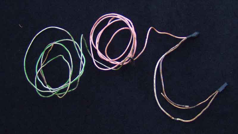 Click the thumbnail for information on the ballast resistance.
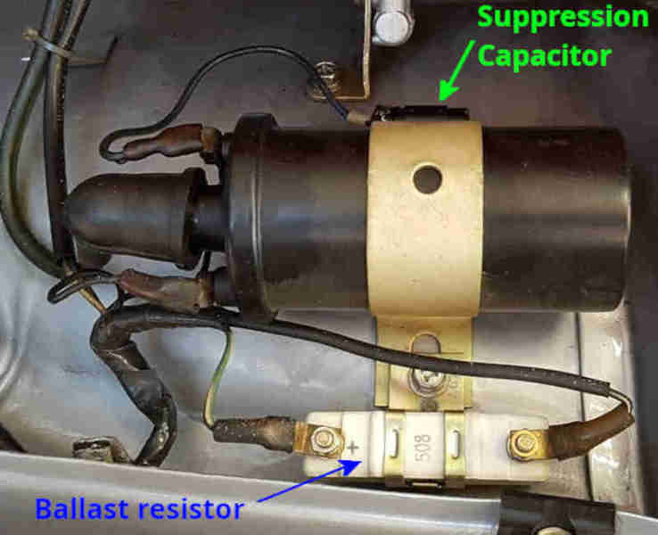 Whilst the MGB ballast resistance is a length of resistance wire contained in the harness and not an identifiable component other marques and models and some after-market coils for the MGB may use a discrete resistor in the shape of a rectangular block with two terminals mounted near the coil.
Is this a ballast resistor?
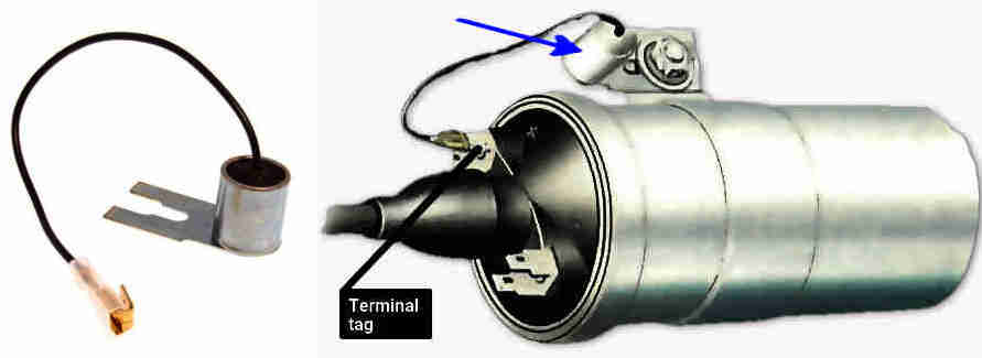 Quite a few cars will have a component that has a wire going to the coil +ve (or SW) terminal and a metal tag secured under a coil fixing bolt, but these are radio interference suppressors. They are capacitors that help to damp electrical noise spikes and can be found on the instrument voltage regulator, fuel pump, indicator flasher unit, alternator, electric screen washer pump i.e. anything with a motor or switch that can generate electrical noise. They are similar to the ignition condenser in a distributor in that both are capacitors, but whereas the condenser has values of about 0.2uF and 600v a suppression capacitor will be about 2uF and 100v and the two are not interchangeable. Originally cylindrical, they can also be rectangular.
Isn't the coil used on rubber bumper cars a 9v coil? No. This has come about from connecting a voltmeter to a rubber bumper coil on a running engine and not understanding what the meter is telling you. You will see about 9 or 10v on an analogue meter (digitals can be different or give no usable reading), but that is because the meter is averaging the voltage with the points open which will be 12v with the voltage when they are closed which will be something less. To see the true picture you have to measure the voltage on the coil +ve with the engine stopped, points closed, and ignition on. The ballast resistance should be of a similar resistance to the coil, so with the correct coil and ballast resistance on a rubber bumper MGB you should see about 6v, not 9v, hence it is a 6v coil. If you do see something significantly different to that then there is something wrong with your coil, ballast resistance or ignition supply voltage.
What about a coil with an internal ballast resistor? It matters not a jot whether a coil has an internal ballast or not - a coil is either a 12v coil or a 6v coil. Originally all coils were 12v and contained nothing but many thousands of turns of copper wire. Subsequently manufacturers produced 6v coils for 12v systems which when used with wiring that includes a ballast resistance in the circuit allow the spark to be boosted during cranking, and as a side-benefit they give an improved spark at high rpms. 12v coils for older systems are still needed of course and at some point someone had the bright idea of putting a ballast resistance inside the can with a 6v coil so making it a 12v coil! This meant they only had to produce one winding unit instead of two reducing production as well as material costs, and you end up with a 12v coil that also has the improved spark at high rpms - albeit much higher than a factory MGB ever produced. So if anyone starts talking about internal ballast ignore it. A coil is either a 12v coil of about 2.5 to 3 ohms or a 6v coil of about 1.5 ohms, and the only way to be sure what you have is to measure it - including newly purchased coils as suppliers descriptions and manufacturers packaging and markings can be confusing if not downright incorrect.
Why did they change to 6v coils anyway? The main benefit of the 6v coil is that it enables the ignition to generate a more powerful spark during cranking. Even a tip-top battery will have its voltage reduced during cranking, typically to around 10v, because of the very heavy load of the starter motor. On a 12v system this means the primary current and therefore the HT spark will be reduced. But by using a 6v coil and a special starter solenoid, the ballast resistor is bypassed during cranking and the maximum available battery voltage will be connected directly to the coil, i.e. 10v, which results in a stronger HT spark than when running. This is beneficial to all cars under extreme conditions i.e. very cold, thick oil, battery in less than perfect condition due to age or short journeys in winter with lights, heater etc. always on. The more powerful spark was even more important on North American emissions controlled engines which were harder to start. Note that all 18V engines had the 2M100 starter with the coil boost contact, but it was unused until the start of rubber bumper production. All V8s had the 6v coil system. There is also said to be another benefit of 6v coils and that is they have lower inductance than a 12v, and hence lower 'reluctance' to build up flux, therefore a shorter time to build up full flux for the next spark, and so a greater ability to supply a full spark at higher revs. However the rev limit of the MGB didn't change over its life and the change was more of an industry standard thing than aimed specifically at the MGB. Since the V8 with twice the cylinders, half the dwell, and hence half the reflux duration of the four cylinder has no problem delivering much the same peak rpm, Jaguar V12 engines even more so, this aspect is largely irrelevant. Whilst the plug gap was able to be increased from 25 thou to 32 thou with the introduction of 6v coils this may be much to do with the change from the 25D4 distributor to the 45D4 and perhaps an improved resistance to breaking down at high HT voltages, than greater energy from the coil. The special solenoid has an extra spade terminal which puts out a full 12v on the white/light-green (white/light-blue on factory V8s) wire to the coil when the solenoid is energised. This wire goes to the +ve terminal of the coil, together with the same coloured wire from the harness ballast. A 6v coil also generates half the heat of the 12v coil the other 'half' of the heat is generated in the wiring ballast resistor, but again this is neither here nor there. Many people replace the starter with a modern geared or 'Hi-torque' unit and many of these don't have the additional contact to boost the coil voltage on starting. Whilst under most condition the car should still start pretty well, under adverse conditions it can make the difference between starting and not starting. There are a number of ways to get round the lack of 'coil boost' contact, see here.
May 2010: Should I reverse the coil connections when changing the car's polarity? It's often recommended, but is it really necessary? And what are the benefits and drawbacks? Early, positive-earth cars had coils with terminals labelled 'SW' and 'CB' and Mk2 negative-earth cars have coils with terminals labelled '+' and '-'. For connections of these and other variations read on:
- I have an original positive earth car and a coil with SW and CB terminals: Connect the SW terminal to the ignition SWitch using the white wire and the CB terminal to the distributor Contact Breaker aka points using the white/black wire.
- I have a positive earth car and have to replace the coil with a modern one: If the coil has a push-in HT connection connect the white wire from the ignition supply to the '-' terminal and the points wire to the '+' terminal. This will adversely affect the HT spark slightly but unless you can get a good SW/CB coil from somewhere you may have no choice. Note that new coils advertised as being for Mk1 cars have the terminals labelled '+' and '-' despite having screw-in HT connections (such as this one from Moss Europe), it's not known whether these wired internally for positive earth or negative earth. This method may show you, failing that try the connections first one way then the other, and if one way seems to work better then go with that.
- I have a positive earth car that has been converted to negative earth: Ideally fit a modern +/- coil, otherwise the wiring to an original SW/CB coil should be reversed i.e. the white wire from the ignition supply should go to the CB terminal and the points wire to the SW.
- I have a positive earth car that has been converted to negative earth and need to fit a modern +/- coil: This is a better option than reusing the original SW/CB coil - connect the white wire from the ignition supply to the '+' terminal and the white/black points wire to the '-' terminal.
- I have an original chrome bumper negative earth car and need to fit an SW/CB coil: Ideally don't, get the correct +/- coil for your car, but in an emergency connect the white wire from the ignition supply to the CB terminal and the white/black wires to the SW terminal.
- I have a rubber bumper car and need to fit an SW/CB coil: As above ideally don't, get the correct +/- coil for your car. In an emergency it can be done but using the existing wiring will halve the HT spark energy and you may have problems starting and running because of the ballasted ignition system on those cars. To avoid that, and if you can do so, connect a temporary wire from the white or white/brown terminals on the front of the fusebox, second fuse up, to the CB terminal on the coil and the white/black wires to the SW terminal.
Some cars had factory-fitted radio interference suppression capacitors fitted at the coil, these should be connected as described here. Some cars may have had after-market ignition conversions involving an external ballast resistance, typically as here, these are completely different to and independent from suppression capacitors.
This Lucas document (p11) states that a negative polarity should be presented to the insulated plug terminal with positive to the plug body. This is because electrons (which travel from negative to positive, unlike conventional current or charge flow) would rather jump from the hotter central electrode to the cooler body than the other way round, which requires about 10% more HT voltage to get the spark started. Negative HT also results in less erosion of the rotor, as one quarter of the amount of metal is transferred from each cap contact to the rotor over a given length of time, instead of all of it being transferred from the rotor to the cap contacts. Remember HT voltage will rise until the plug fires, then more-or-less stops there for the duration of the spark. Typical measured HT voltage for a 25 thou plug gap will be 6 to 10kV, 10% being 600v to 1000v of course. So it would make sense to reverse the coil LT connections when reversing the battery. But another feature of the coil is that the 'other' end of the HT winding doesn't go to the can as you might suppose, but is connected to one end of the LT winding. Originally this would have been the points terminal (CB), and the reason is that when the collapsing flux generates the HT voltage in the HT winding it also generates 200-300v in the LT winding. Connected as originally this voltage is added to the HT voltage to boost it, known as the auto-transformer effect. Reverse the LT connections to correct the HT polarity and you lose this boost. So which to do? As reversing the coil connections when reversing the battery adds 600 to 1000v, but loses 200-300v auto-transformer effect, it is better to reverse the LT connections. But it would be better still to buy a negative earth coil and retain both effects, which is what the Lucas document recommends.
How can you determine the polarity of a coil? You could measure from the HT terminal to each LT terminal, and the one with the lower resistance i.e. the junction between the two windings should go to the points. But that is looking for 3 ohms difference in over 5000 ohms, which would need a digital instrument with at least 4.5 digits to reveal. You could do an open-circuit bench-test and see which LT polarity jumps the largest gap (a cold gap, so HT polarity difference won't matter), but that will result in some very high voltages in the coil which probably isn't wise. A test with a controlled gap in the HT circuit is no good as the voltage will stop rising when the gap fires. You may be able to tell by looking at the two induced voltages on an oscilloscope. If that on the HT lead is negative with respect to earth (as it should be), and the LT terminal connected to the points is also negative with respect to the LT terminal connected to the ignition supply, then the implication is that the required auto-transformer effect is also present, but I have not tested this. I did wonder whether you could use the effect mentioned above whereby the auto-transformer action tends to reduce the current displayed on an analogue instrument, but because the induced voltage in the LT winding will always be opposite to the battery current, no matter what coil you have on what polarity car or which way round, the reduction will always be present. You can probably assume that an original coil from a positive earth car marked SW and CB is a positive earth coil, and that from a late car marked + and - is a negative earth, but that doesn't help one jot with replacement coils, where even if you can get one marked SW and CB there is no guarantee it's internal connections are for positive earth. Note that at least one edition of 'MGB Electrical Systems' is incorrect in that it states "On negative earth cars as long as the distributor is connected to the + terminal (of the coil) the test should be unnecessary". On a negative earth car the distributor (i.e. the earth supply to the coil) should be connected to the - terminal of the coil, and the 12v ignition supply (the positive supply to the coil) should be connected to the + terminal. A number of sources talk about using a graphite pencil tip held in a spark gap, and when the polarity is correct there will be a brighter spark or 'flare' from the pencil tip to earth.
However having tried that I found it very inconclusive, there is a much better way using an analogue meter between the HT lead and earth. You still need a spark gap e.g. a spare plug connected to the HT lead laying on the block and not just an open-circuit lead, then remove the distributor cap and flick the points open and closed by hand. With the correct polarity the meter (with -ve connected to the coil lead and +ve to earth) should show an upward flick as the points are opened, and a downward flick as they are closed again. This opposite flick is because the coil is a transformer, which will generate a voltage in the output when current commences flowing just as it will when it ceases, but only when it ceases and the condenser is in circuit because the points are open will it generate the higher voltage needed to fire the plug. One source recommends connecting the meter across a plug in the engine and cranking, but with the upward and the downward flicks being so close together it may not be clear whether it is the opening of the points or their closing that is causing a downward flick.
When all is said and done, whilst when some documents were written ignition systems may have needed every volt they could get, in an MGB ignition system there should be more than enough energy to be able to ignore all these variations. However it could just possibly make the difference between starting and not starting if any one or more of points, plugs, condenser, rotor, cap or leads are in poor condition. It's even less of an issue with modern electronic HV systems, for a start 'wasted spark' ignition systems fire two plugs at the same time (both being fired when either plug needs a spark hence the spark to the other plug is 'wasted') but these systems always fire one plug one way and the other plug the other, so plug polarity with this system can't be an issue. Some manufacturers apparently fit different plugs for +ve HT than to -ve, but this is more about saving money in terms of the amount of platinum on each electrode than plug performance. Yet another source claims that on a system with dual polarity HT i.e. wasted spark you can double the life of the plugs by rotating the plugs between positive and negative HT positions. If that really is the case, then we could do the same simply by reversing the coil LT leads every now and again! But it doesn't seem to be worth the bother against a few quid for new plugs every 10k. Speaking of which, I bought a set of Bosch Super 4 4-electrode plugs way back in February 1999, since when they have done about 34k miles (April 2016), and still show no signs of electrode erosion. Double the price of 'conventional' plugs, but since they have done 3.5 times the recommended life and still look as good as new, good value.
November 2018: What is an oil-filled coil? Originally coils were 'dry', then at some point oil was added. Two possible reasons - the first being better heat transference from the winding to the coil case and thence away from the coil altogether, the seconds probably to do with preventing internal breakdown as will be seen below. In my experience an 'oil-filled' coil clearly makes a sloshing noise when shaken, so only partly filled and not completely filled as the description implies. I've seen a claim that Bosch coils are completely filled and don't slosh, but that would mean the oil would expand as it heats up and put pressure on the seal between the case and the end that carries the connections, which seems unlikely. November 2022: Some manufacturers have gone back to 'dry' coils using a resin compound. And that leads on to:
January 2011: Should the coil point up or down? From time to time this question crops up, and there are various comments about oil-filled coils being used pointing downward so the oil cools the HT connection. On one recent discussion someone who should know better roundly castigated everyone saying they should read the Workshop Manual, because the answer is in there, when it isn't - directly at least. What is in the WSM that is interesting is a description of a test-rig, where it says the coil must be mounted at 45 degrees, with the CB terminal uppermost, so that it's internal connection is not covered with fluid and any internal tracking between the iron core and the primary lead will be revealed. One would have to know that oil is used in HV systems to resist tracking (a spark will jump an air-gap more readily than it will jump an oil-filled gap) to work out that if the CB internal connection must be uncovered during testing to reveal any faults, then it should be covered in use to resist any tracking developing. Thus, the coil when mounted on the inner wing of 4-cylinder cars or radiator mounting panel of V8s should point downwards. Early MGBs (possibly just 3-bearing) have the coil mounted horizontally to the engine, so perhaps the terminals of the coil should be vertical with the CB (-ve for later coils) in the lower position. Again I have seen a claim that Bosch oil-'filled' coils should be mounted terminals uppermost or they leak when they get hot! Seems very unlikely to be correct, on several levels. Incidentally engine-mounted coils will get hotter than inner-wing mounted coils, as they will be picking-up significant mechanical heat as well as electrical. Which brings me on to:
January 2013: Hot coils. There has been some discussion on this in various places for a while now, and it's a fascinating and complex subject given the apparent simplicity of the points/condenser/coil ignition system. Coils, like alternators and many other components, do run hot to the touch and are designed to be able to cope with it. The question is, how hot is normal, and how hot is too much? I'd say that if the average person can keep their hand on it, it's probably not too hot. If they can't, it probably is too hot. But that's very subjective, and the real arbiter should be whether there is a problem with the running of the car or not. If not, and it just seems hot when you touch it, then ignore it. If there IS a problem with running then there is definitely something wrong somewhere, but it might not be the coil. One thing for us in the UK to remember is that these cars run perfectly well in desert states in America at ambient temperatures of well over 100 degrees Fahrenheit. The coil is behind the radiator (if not bolted to the engine), and so is obviously expected to work correctly at the highest engine compartment temperature that Abingdon expected. If someone in the UK is having a problem, especially at the moment, then it's being caused by a definite fault.
Contrary to what one person writing elsewhere is insisting, the minimum resistance of a 12v coil is not 3.5 ohms. The Leyland Workshop Manual specifies 3.1 to 3.5 ohms (i.e. 3.5 ohms is the maximum), Sport coils can be as low as 2.4 ohms, and coils for electronic ignition systems can be much lower than that. The writer is getting hung-up on the fact that if you connect 12v to a 12v coil then with about 4 amps flowing through it developing 48 watts of heat it will overheat. But all that means is that you shouldn't leave the ignition switched on with the engine stopped. If you need to do that for diagnostic purposes on other components then disconnect one side of the coil, remembering to reconnect it afterwards.
As an electrical component it will will generate heat when it is powered and its temperature will rise. It has to be able to dissipate that heat somewhere or it would get hotter and hotter until the component was destroyed, and in the case of the ignition coil that heat is dissipated to the surrounding air i.e. in the engine compartment. But it can only start dissipating heat when it gets hotter than its surroundings, and so it will always be hotter than the ambient air in the engine compartment. Therefore it follows that on a winter's day with icy air blowing through the radiator that it will be much cooler to the touch than in high summer when the radiator is pumping out masses of heat.
I've checked both mine - V8 with a ballasted system and roadster with an un-ballasted - and after running for about 20 minutes in 8 to 10C ambient they were only round 40C, which is only warm to the touch. On one day with an ambient of about 15C the V8 coil was 52C, and on another with an ambient of 21C it was 58C. So with each increase in ambient there is a similar increase in coil temperature, as expected.
July 2013: In the midst of this heatwave I've been checking both cars again. The V8 at an ambient of 27C saw the lower part of the coil at 62C (the upper was a little cooler), so again a correlation between the increase in the ambient temperature and the increase in the coil temperature. Whilst 40C (10C ambient) is only warm, 62C is very much hotter to the touch. The engine compartment temperature varied between 40C bowling along the M6 round Birmingham at 9:30am, 45C coming back at 1:30pm, and in some stop-start traffic round Solihull with the fans on it got up to 58C. With the roadster at 26C ambient the upper part of the coil was at 67C (in this case the lower part was a little cooler). Higher than the V8 as before, but a slightly smaller difference than at lower ambients. The engine compartment in stop-start traffic round Solihull got up to 50C.
July 2016: Over the last two days of 30+C ambients I've been checking the V8 (the roadster is part-way through a clutch change). On both afternoons the engine compartment got up to 64C (measured closed with a probe through a grommet) and stopped with the bonnet open the coil measured 68C. No problems hot starting - either immediately or after a few minutes, so what the problem was in 2014 (intermittent problems in May, June and July even though it wasn't as hot as it is at the moment) I don't know.
If you think your coil IS too hot, or you have running problems, then you might like to read on for some specific tests you can do.
Some have wondered if a faulty tachometer could cause it. It's highly unlikely, with either early or late versions. It would have to be capable of injecting additional current into the ignition system, which given the internal circuitry is not possible, without showing some effect at the tach at the very least. Whilst both tachs can affect the ignition system under certain fault conditions, they would cause a significant misfire or stop the engine running altogether, and it would show on the tach. Neither would another cause be the condenser going short-circuit, as the most obvious indication of that again would be misfiring at best (with an electronic tach jumping around all over the place) or complete failure of the ignition at worst.
There are two factors involved in how hot a coil gets. The first is how much energy is being put into it which is a factor of its resistance, the voltage being applied to it, and hence the current flowing through it - the heating effect. The second is how fast it is dissipating that heat. How hot the coil will get over time depends on the temperature difference between the coil casing and the surrounding air in the engine compartment. On starting a cold engine they are both the same, so no dissipation, so the coil starts to heat up. As it does so it starts to dissipate heat, and the hotter it gets with respect to its surroundings the faster it will dissipate heat. Eventually the dissipation rate equals the heating effect from the current, and it reaches a stable temperature. A coil with a massive finned heat sink in arctic conditions will probably barely get warm. Wrap it in foam or fibre-glass insulation and it will almost certainly overheat. Under normal circumstances the coil is always capable of dissipating more heat than is being generated, if it didn't it would just get hotter and hotter until it burst into flames or burnt out.
But how should you measure it? Metal probes will only be picking up heat from the part of the probe that touches the surface of the coil, the rest of the probe surface will be radiating it and averaging the reading, so things like oven and personal thermometers are unsuitable, although you could put a piece of polystyrene insulation over the probe and a small area of the coil surface. You could use junior's ear thermometer perhaps, but I have no experience of those. You could also use an infra-red thermometer with laser pointer, but bear in mind the temperature is not being taken at the laser dot but over a much wider area, so the lens of the infra-red detector will have to be pretty-much on the coil to avoid picking up lower-temperature objects around it and averaging the result downwards. Perhaps those LCD strips would be the most consistent, but then they seem to have a relatively low range of a dozen or so degrees Centigrade, you would need to know which 'ball park' you were in to start with. The ultimate coil temperature will also depend on the air around it, i.e. the engine bay temperature. All in all not very conducive to getting comparable readings from different people using different methods on different cars. I measured mine with an infra-red thermometer placed right on the coil.
The Workshop manual says chrome bumper cars have coils of 3.1 to 3.5 ohms (cold, higher when hot), and with a switch-on voltage of 12v Ohms Law gives us 3.9 amps with an average coil, which is what is specified in the Workshop Manual, and this current is the first thing to check. This would generate 50 watts of heating effect (voltage squared divided by resistance) and is going to generate too much heat in the coil over a long period and can damage it. (If you need the ignition on for a long period with the engine stopped for any reason, remember to disconnect the coil as the points are usually closed when a running engine is switched off and allowed to come to rest on its own). If the current is significantly higher than 3.9 amps you need to measure the coil primary resistance, with the wires removed from the terminals. A low resistance coil will carry more current and get hotter than it should. If the current is lower, then you could have bad connections or bad points which will be causing a low HT voltage, but the coil itself will be running cooler than normal.
However, that's at switch-on. When running with points (electronic ignition systems are usually very different) the 25D4 distributor is only energising the coil for 67% of the time (derived from a dwell angle of 60 degrees in a 4-cylinder distributor i.e. 90 degrees per open/closed cycle). But now we have typically 14v as the system voltage so the heating effect is 42 watts (voltage squared divided by resistance times percentage energised divided by 100), but even that is not the full story. The coil is a transformer and has inductance and the effect of inductance is to cause the current to rise over a short period of time when voltage is connected, not instantaneously, so the heating effect is reduced still further. The Workshop Manual quotes a running current (i.e. the average of no current for some of the time, partial current for some of the time, and full current for some of the time) of only 1.4 amps at 2000 rpm which implies only However the readings in the Workshop manual will have been made many years ago, and hence on an analogue meter, and the reverse EMF generated as the points open tends to kick the needle back a bit and give an artificially low reading. Nevertheless if you connect an analogue meter on its current scale in series with the coil and run the engine, this is the current you should see. If the static current was correct but the running current is too high or too low, you need to check the points gap or dwell. If your points gap is too small you will get a high dwell, higher current reading and the coil running hotter. If too large you will get a low dwell, lower current reading and the coil will run cooler. Dwell is a dynamic (i.e. with the engine running) method of measuring points gap and avoids putting feeler gauges that might be oily against the points contact surfaces. With the correct gap you should get the correct dwell, and vice-versa, but there are some faults that means this isn't the case. Going back to current, on a running engine a digital meter may well show something completely different or no usable reading at all, depending on model and type. That's for a 25D4 distributor. With a 45D4 the points are only closed for 57% of the time, giving a slightly lower average current and hence lower heating effect.
Rubber bumper cars are significantly different. They have a lower resistance coil of 1.4 to 1.6 ohms i.e. half that of the chrome bumper, but it is in series with a ballast resistance of a similar value which means the current through the coil ends up being much the same as on a chrome bumper car. So with the same current, but half the resistance, you get half the heating effect in the coil. The other half of the heating effect is being developed in the external ballast resistance so not contributing to coil temperature. You should see more or less the same static and running currents in the ballasted system as in the unballasted, with the same causes if the current is higher or lower. There could also be faults in the ballast resistance so this should be measured from the white or white/brown at the fusebox to the white/light-green at the coil +ve, again with the wires removed from the coil terminals.
I did a bench test, with a 12v coil in series with a 6v coil and its ballast, connected to 12v. This is a static test i.e. no points making and breaking the circuit, but having the two in series halves the static current and makes it similar to that in a running engine. After an hour or so in an ambient temperature of 10C the coils had stabilised, with the 12v coil at 30.3C, and the 6V at 21.9C. Subtract the ambient, and you end up with the 12v coil having gained 20C and the 6v coil 12C. This verifies that the 6v coil has about half the heating effect of 12v coils, but more importantly my running tests indicate that the engine bay temperature in summer is going to have significantly more effect on coil temperature than the current flowing through it.
This table compares the coil energising time and hence heating effect for various points ignition systems found on the MGB:
| Note that if you use a rubber bumper coil without a ballast you will get almost 100 watts of heating effect. | ||||||||||||||||||||||||||||||||||||
| It can seen clearly that at anything other than high revs the heating effect of this system is significantly less than that of a rubber bumper points system, and far less than a chrome bumper system at any likely rpm to be encountered. However the 32C5 coil originally provided with this system should really only be used with a variable dwell electronic ignition system or it can overheat. If a points distributor is substituted the heating effect will rise to 26 watts if a ballast is in circuit which should be OK, but if unballasted it will rise to 180 watts which almost certainly won't be. | ||||||||||||
I've also seen a claim that variable dwell saves horsepower. Well, yes, but if you do the maths at mid rev range that works out at 0.015HP! And that reduces the with higher revs.
May 2018: Someone on the MGOC forum recently bought a new ignition lock and switch for his 1978. As it seemed to have some extra wires he checked the old and new multi-way plugs carefully and discovered that as well as having two extra wires - a grey and what looked like a purple - the brown wire was in a different position in the connector plug. The effect of this is that had he connected up the switch, when putting the ignition key into the lock he would have connected an earth to the brown wire in his main harness, damaging both the new switch and his harness!
In the event it looks like his car has suffered a short-circuit at some time which damaged the plastic connector and allowed the pin on the brown wire to be pushed out, so someone fitted it in another hole, which just happens to coincide with the purple/pink on the switches that are being supplied today (BHA5292). The extra switch wires - grey and purple/pink - are used on American spec cars and there should be no matching wires in the UK main harness connectors. So the recommendation, when replacing parts like this with multi-way connectors, is to check the wires line up correctly first!
Ignition Switch Connections
Ignition Switch Removal
Ignition/Steering Lock
North American 'Key in' Warning
Ignition Keys
Types used:
| May 62 - Nov 67 | Mk1 | When no steering lock provided | 13H337 | Spades on switch
| Nov 67 - Dec 70 | Mk2 | When no steering lock provided | 13H926 | Spades on switch
| Dec 70 - Feb 72 | 230617-275645 | Not North America | BHA5709 | Use BMK2259 | Combined lock and switch
| Feb 72 - Sep 74 | 275646-361000 | As above | BHA5215 | 37H7708 | Use BMK2259 | Spades on switch
| May 62 - Sep 74 | 101-361000 | As above | BMK2259 | 37H5934 | Spades on switch
| Sep 74 - end | 360301-on | As above | BHM7056 | BHA5398 | Note 1 | Lock with switch, multi-plug
| V8 | 18G8905 | Note 2 | Lock with switch, bullets
|
| May 62 - Aug 68 | 101-152454 | Sweden, Germany, Finland (Oct 67), Austria (Jan 68) | 13H4180 | 27H6237 | BMK2259 | Spades on switch
| Aug 68 - Dec 70 | 152455-231338 | Above plus France (Sep 69) | 13H4862 | 27H6237 | Use BMK2259 | Spades on switch
| Aug 68 - Dec 70 | 152455-231338 | As above | 13H4862 | 27H6237 | BMK2259 | Spades on switch
| Nov 67 - Sep 69 | 138401-187840 | North America | BHA4715 | 37H4114 | Lock and switch NLA
| Sep 69 - Aug 71 | 187211-258000 | North America, Sweden (Dec 70) | BHA5050 | BHA5056 | Alternatives | Lock and switch NLA
| Aug 71 - Aug 72 | 258001-296000 | As above | 18G8906 | Combined lock and switch
| Sep 69 - Aug 71 | 187211-258000 | As above | 18G8901 | BHA5070 | Lock and switch NLA
| Aug 71 - Aug 72 | 258001-296000 | As above | 18G8905 | BHA5070 | Lock with switch, bullets
| Aug 72 - Aug 73 | 294251-324942 | As above | 18G8984 | BHA5128 | Bullets on wires
| Aug 73 - Aug 73 | 324943-325855 | As above | 18G9064 | BHA5288 | Lock and switch NLA
| Aug 73 - Aug 73 | 325856-328800 | As above | 18G9118 | BHA5288 | Lock with switch, multi-plug
| Aug 73 - Jun 76 | 328110-410000 | As above | 18G9119 | BHA5292 | Multi-plug
| Jun 76 - end | 410001-on | As above | 18G9119 | BHA5069 | Multi-plug
| | ||||||||||||||||||||||||||||
Note 1: Switch no longer available, use BHA5292. This is the North American switch with extra grey and purple/pink wires, the original switch may have the grey but not the purple/pink. The remaining four wires should connect directly to the same colour wires in the main harness, but double-check before plugging in. The grey and purple/pink should not have corresponding wires in the other half of the multi-plug.
Note 2: Prices for replacement lock with switch for the V8 varies from �31 to �120! If only the switch has failed it may be worth trying BHA5292 as they can be had for little more than a tenner, and if it fits it saves having to cut off the lock which cannot be done by drilling up from below like it can with the earlier side-entry locks. You would need to cut off the multi-plug, discard the grey and purple/pink wires, and solder bullets to the remaining brown, white/green, white and white/red wires.
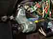 Dash type is easy with just the usual locking ring. When associated with a steering lock the switch seems to be held in the lock body with a small screw, the type and position of which varies depending on the type of lock.
Ignition Theory See also these pages from Tjellvar Harbom in Sweden and this document from Frodo Irrxsom in Norway (must be those long winter nights ...)
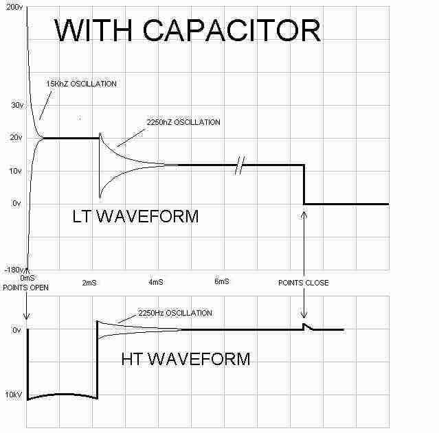 There is a condenser or capacitor connected across the points when they are open and this component is vital to the ignition system. Its main purpose is not, as many people think, to protect the points from burning (although it does this as well) but to cause the coil to generate a good strong spark at a known time (how to identify condenser failure). Because the coil is a transformer it will only generate a voltage in the HT (and hence a spark) when the current through the primary is changing, not when it is steady. The faster the current change and the greater the voltage swing in the primary the higher the output voltage generated. When the points are opened, instead of the current immediately ceasing to flow through the coil as you might think, it continues for a very short time while it 'charges up' the condenser with the voltage spike that would otherwise arc across the points. It is only when the condenser is charged that the current ceases to flow. Furthermore the condenser and coil, when the points open, are interconnected in such a way as to form a tuned L/C circuit (L = inductor or coil, C = capacitor or condenser) and this causes the current in the coil primary to oscillate rapidly (about 15 thousand times per second) back and fore with a peak-to-peak voltage swing of about 400v. The effect of this is to generate an output pulse, and hence a spark, of about 10 thousand volts that lasts for about 2 thousandths of a second (i.e. 2 milliseconds, or 2mS). Not very long, you might think, but at 3600 rpm any one cylinder is firing 30 times a second i.e. every 33mS, so at that speed the spark lasts for 22 distributor degrees, which is 44 crankshaft degrees! By comparison, the spark duration without a condenser is only about 0.2mS i.e. one-tenth as long.
The secondary effect of the condenser is to cause the spark to occur at the correct time. With the condenser in circuit the high-frequency oscillation that occurs immediately the points open means that the output voltage and hence the spark commences just 0.02ms, or 20 millionths of a second, after the points open. Even at 5500 rpm the effect of this delay is less than 1 crankshaft degree, something that is easily compensated for by the centrifugal advance of the distributor. This high-frequency oscillation also protects the points because the voltage spike that occurs the instant the points open decays to zero again (as part of its first cycle of high-frequency operation) in about 20 millionths of a second, and this nips the spark off. Without the capacitor the spark only ceases when either the voltage drops sufficiently or the points open sufficiently, and this takes about 2mS. During this time the points are arcing, which, as well as eroding them and causing spikes and pits, means that some current is still flowing through the coil for the duration of the arcing, which delays the main collapse of the flux and hence delays the output voltage pulse and therefore the spark. This delay is again about 2mS and does not vary much with rpm. This 2mS delay effectively retards the spark during cranking by about 1 crankshaft degree, i.e. not very much. But the delay increases to about 24 crankshaft degrees at 1000 rpm, 48 at 2000 rpm, etc., which means that as well as only having a very short duration spark, it is also very retarded even at quite low speeds.
The capacitor has a value of about 0.2uF and this value is critical for a good HT spark. Experimentally varying the value by quite small amounts shows little variation in voltage waveforms on the LT or HT or visually in the spark but a there is a definite reduction in the strength of the audible 'crack' heard at the spark plug.
You can see the effect of a weak or failed (open-circuit) capacitor in this simple test (only do this with conventional points/coil ignition): Remove the distributor cap, remove the king lead from the cap and tape it to a length of wood. Turn on the ignition, flick the points open and closed by hand, and see just how far the spark will jump from the end of the king lead to the block. It should be at least 1/4" and maybe as much as 1/2" even with a non-sport coil and make a good 'crack' sound. This shows the effect of having the condenser in circuit. Now close the points and interrupt the points lead somewhere else e.g. on the coil terminal to show the effect of NOT having a condenser connected across the break in the circuit. You should find that as well as much arcing at the coil terminal, the spark at the king lead will barely jump a normal plug gap, let alone 1/4" or 1/2". You also get a very 'thin' spark, and it makes very little noise. This is how an open-circuit condenser causes poor or non-running as well as burned points. Note that a short-circuit condenser will prevent the engine running at all as it effectively shorts out the points and prevents any spark being generated.
Experimentally varying the system voltage applied to a 12v coil at the SW or +ve terminal shows a fairly linear reduction in HT pulse duration as the voltage reduces, but the HT voltage at the plug does not start reduce until the supply voltage has been reduced to something less than 6v. This is because the HT voltage measured at the plug is controlled by the plug gap - as soon as the HT voltage rises high enough to jump the gap it will do so, which stops the HT voltage rising any further. The voltage at an HT lead that is not connected to a plug with a 12v supply at the coil, is much higher, and reducing the supply voltage shows a fairly linear reduction in voltage as well as duration.
Ignition has to occur at a fairly critical time (hence 'ignition timing') in the piston cycle, and has to be altered according to what the engine is doing at the time - e.g. starting, cruising, accelerating, low rpm, high rpm. The distributor has to manage most of this by itself, but usually with a little help from a vacuum line from the inlet manifold or carburettor. Quite a task for an electro/pneumatic/mechanical device invented 70-odd years ago. There have been many different distributors used over the years, each with different characteristics. Many of the changes in later distributors were to cope with increasingly stringent emissions regulations, which usually had a negative effect on performance. In general, the earlier the distributor the better the performance.
- Starting is easier when the spark occurs later in the cycle - anything from 0 to 10 degrees Before Top Dead Centre (BTDC) - the static timing figure.
- Once the engine has started and is idling the timing is advanced - typically to 11 to 15 degrees BTDC. This advance (called centrifugal advance) is achieved by weights spinning in the bottom of the distributor. They try to fly outwards due to centrifugal force, and this movement is used to alter the relationship between the points cam and the drive shaft, which causes the points to open and close a little earlier in the cycle.
- The weights are restrained by springs, so that they move gradually as engine speed increases, maximum advance being achieved at anything from 2,200 to 6,000 rpm, adding anything from 17 degrees to 32 degrees to the static timing figure. Each weight has its own spring and the two springs usually have different characteristics. We need this progressive timing advance because the fuel/air mix burns at a constant rate irrespective of engine speed, and if the timing were not advanced as rpm increased, the burn would occur further and further into the piston down-stroke, converting less of its energy into motion and more into heat. This is wasteful of fuel and potentially damaging to the engine.
- When the car is accelerating with large throttle openings, more fuel/air mix is being drawn into the cylinders and ignited, so greater pressures are generated inside the cylinder. There is a point at which the pressure becomes so great that when the spark ignites the mixture, instead of the normal burn, we get an explosion or detonation. This explosion occurs while the piston is still moving upwards and puts great stresses on the engine, and can burn holes in the top of the piston. Fortunately this condition is frequently audible as a metallic 'pinking' or 'pinging' sound when the engine is under load e.g. labouring up a hill. If you hear this you should back off the throttle to stop it, changing down if necessary, and investigate the cause as soon as possible. It is often caused by over-advanced ignition or weak springs in the distributor advance mechanism. With the distributor cap off you should be able to manually twist the rotor arm and spindle in an anti-clockwise direction, against spring pressure, and it should return fully when released slowly. If it does not return at all, or does not return all the way, one or both of the springs may have become detached or stretched. Spring sets for specific 25D4 distributors have been available from Distributor Doctor in the past, but for 45D4 only if you can specify the characteristics of the springs you want. Other places may be able to set-up a distributor with the characteristics you specify. Check that the spindle twists easily, lack of lubrication can cause stiffness and incorrect advance. To prevent this pinking or pinging many cars have a vacuum pipe between the carb (early cars) or inlet manifold (later cars) and the distributor. At large throttle openings the vacuum reduces and this is used to lessen the amount of advance by rotating the baseplate, and hence the position of the points in relation to the cam.
- When the car has reached cruising speed, say 2500 rpm on a light throttle, there is much less likelihood of detonation and the engine will run more economically with maximum advance. The vacuum from the manifold or carb is at its highest and this is used to advance the timing still further from that set by the centrifugal advance. Note that manifold vacuum brings maximum advance into play at idle, and reduces it as the throttle is opened. Carb vacuum has no advance at idle, maximum at light throttle, and reduces it as the throttle is opened further. Vacuum advance adds anything up to 14 degrees to 24 degrees to the centrifugal advance.
|
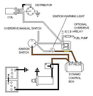
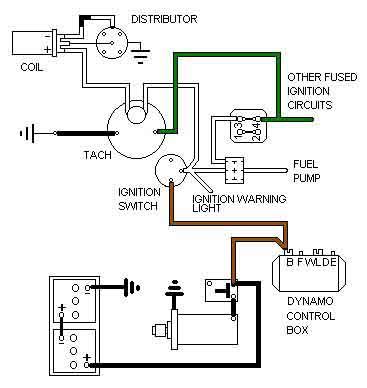
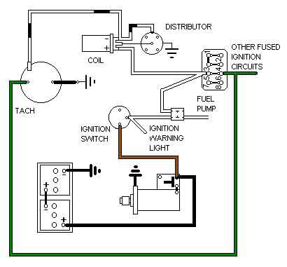
|
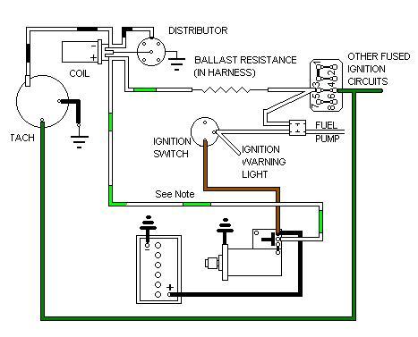
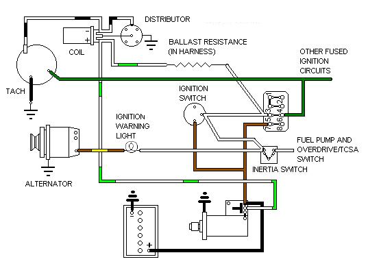
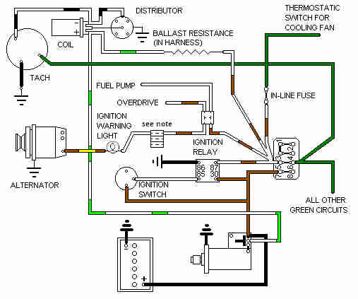
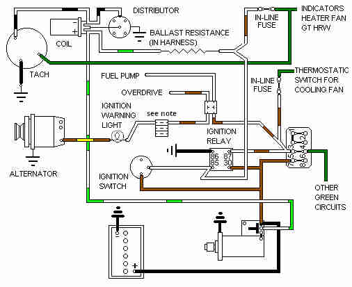
|
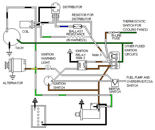
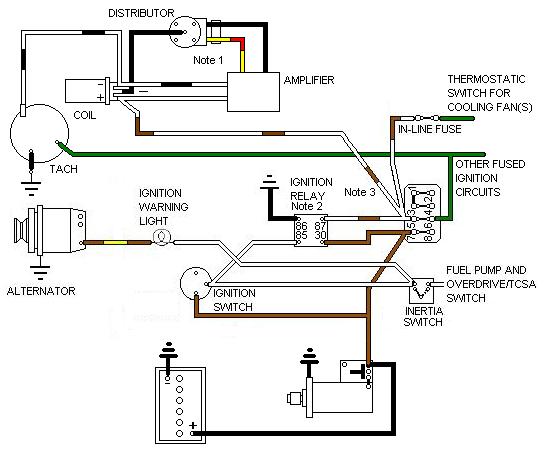
Spark Plugs Amended and updated October 2011
V8 cylinder heads
Spark plug gap
Spark plug coding
Spark plug condition
One question regarding spark plugs with internal resistors is whether they should be used in place of resistive plug leads or caps, or can be used with them. NGK quotes:
So the upshot is that for a factory MGB either resistor plugs or non-resistor plugs can be used equally well, and resistive leads or caps should be used in any event. But if you have done a V8 conversion with EFI and hence an ECU you should use the plugs recommended for the original application, which may well state that resistor plugs should be used. And despite NGKs suggestion that other manufacturers products may suffer from vibration-induced problems I would say that what NGK says can be applied to any reputable manufacturer. But as with anything if you find your car runs better with one make then use it.
Spark plugs for MGBs
4-cylinder: The original Leyland Workshop Manual recommendation for the 4-cylinder engines was Champion N-9Y (and hence its derivatives i.e. RN-9Y for resistor plugs, RN-9YC for copper-cored, or RN-9YCC for double-copper-cored), or equivalents NGK BP(R)6ES, Bosch W(R)7D(C), Unipart GSP4362 to name but three. I'd always used Champion in all my cars until a roadster service years ago when I removed the plugs to check the gap and I succeeded in snapping the insulators off three of them! I'd never broken one before, and after the first I was hyper-careful with the alignment of the plug socket, but still managed to break off two more. When I examined the insulator closely I noticed that instead of the ribs describing nice curves as they always had before, these had flat tops and sides and hence sharp angles between sides and base - a recipe for fracturing I'd have said. Since then I never used them again, sticking to NGK and Bosch, even though they may well have changed the insulators since. December 2017: Based on this picture from a pal Champion have gone back to rounded ribs, but see if you can spot a far more significant change. Quick-fit for very low compression engines? Or to be used with very heavy plug leads?
In February 1999 I bought a set of Bosch Super 4 4-electrode plugs for the roadster, since when they have done almost 40k miles, and still show no signs of electrode erosion. Double the price of 'conventional' plugs, but since they have done 4-times the recommended life so far (November 2017) and still look as good as new, good value. However also in November I started noticing Bee sounding a bit rough at very small throttle manoeuvring speeds. As part of looking into that I decided to replace the plugs (conventional single-point) which improved things, but didn't completely remove it so investigations continued - to find No.2 exhaust valve leaking again. Regardless of that I'll stay with the new plugs, and wouldn't bother with 4-point again, conventional NGKs are cheap enough to replace every 10k as a matter of course.
V8: The original Champion recommendation for the V8 was L92Y, which equates to Bosch W8BC or NGK BP5HS. This is complicated by all sorts of extra characters having been added to the codes to denote plugs with things like resistors, single and double copper-cores, Yttrium etc. but also by manufacturers recently adopting three-digit codes instead of mixed characters, but you should still be able to find them using the earlier designation. I'd also (inadvertently this time) left single-electrode plugs in the V8 for about 25k, and although running seemed fine hot starting eventually got difficult. No visible erosion or excessive gap on these either, but swapping them for a new set solved the problem, so maybe visible condition isn't everything. How long those plugs in plug condition charts have been used for that show the centre and side electrodes eroded very badly, can only be wondered at.
Spark plug gap: Originally 25 thou for the 4-cylinder, changing to 35 thou with the 45D4 distributor in September 1974 and rubber bumpers. This may be because the 45D4 is better at resisting HT breakdown than the 25D4, or it may simply have been a general change in what (then) modern HT systems could produce and withstand. Increasing plugs on a 25D4 to 35 thou may be OK, but then again it may not - and there is no point at all in increasing the gap above that. The V8 was always 35 thou. The greater the gap the higher the HT voltage rises before the plug fires, which increases the stress on the other HT components, increasing the risk of breakdown and misfiring or maybe not starting and running at all. Buying massively thick and expensive HT cables is pointless, as the rotor and cap remain the 'weakest link' as far as the spark jumping a gap is concerned. No standard, road-going MGB should need any more than standard coil, leads (at least, modern silicone rather than the original carbon string), plugs, ignition system (or anything else for that matter). It's going to make no difference to a well maintained car, and if you have a running problem then you should be investigating the cause of that and not try to work round it.
Spark plug coding: Ever wondered what all those letters and number mean? Well you can find out here for Champion, NGK and Bosch. So both 4-cylinder and V8 engines have 14mm thread and 21mm hex, but the 4-cylinder has 19mm reach whereas the V8 has only 12.7mm. There is also a small heat-range difference, the V8 being slightly 'cooler' (perhaps unsurprisingly) i.e. more insulator in contact with the metal surround to give better heat transference. NGK seem to have a wider and finer heat range to Bosch, with Champion between the two, surprisingly, as can be seen here. The heat selection for a plug is a balance between getting hot enough in a given engine to burn off combustion deposits, but not so hot it damages the plug, as can be seen here. If you have a standard engine, with standard plugs, but they are oiling-up in normal use, then that is an indication there is something wrong with the engine i.e. bad rings/bores or valve stems/guides/seals. Selecting a 'hotter' plug in an attempt to keep them clean is not the right way to go.
Spark plug condition:
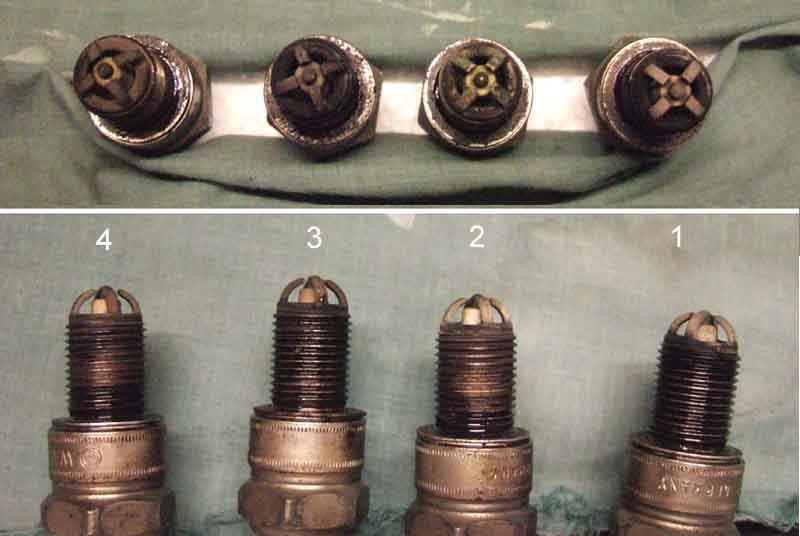 Or 'read your spark plugs'. Lots of examples of specific engine problems (and change interval exceeded - ooops) here from NGK, Champion and Denso, these are my roadster plugs which I reckon are pretty good. They had just done 400+ miles to North Devon and back, removed to check the condition following head gasket replacement which including resetting the carbs, so some hard work up hills as well as some time on a motorway at 70-80. Back two maybe a smidgen richer than the front, so the rear carb weakened a tad. As the HS nuts are awkward to get at with the air cleaner cans on, I made a box spanner, which worked a treat.
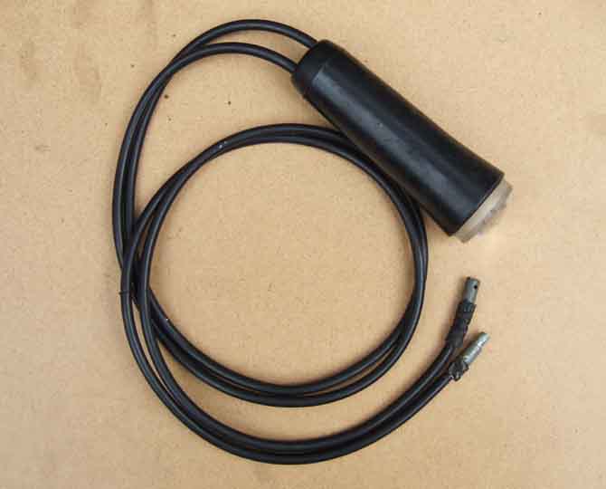 The older type is the 'in-line' type which simply connects in series with an HT lead and has no separate voltage supply. This type tends to have an orange neon discharge tube, which really needs to be used in low ambient light levels and with clean white paint marks on the pointer and pulley marks.
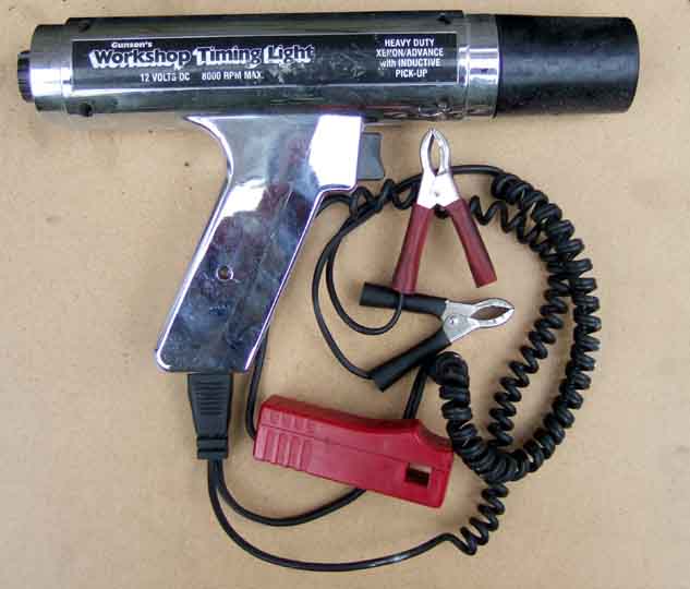 The more sophisticated type has a pick-up which clips onto the HT lead (observing the direction of spark travel from coil to plug in the lead and arrow on the pick-up) and a separate 12v power supply. This type tends to have a white Xenon flash tube, is far more powerful, and is usually effective in bright sunlight. The power supply can be picked up from any convenient 12v point like the brown, white or purple at the fusebox and a handy body earth, it certainly doesn't need to be taken back to the battery. More sophisticated still is the adjustable light with a variable control which can be adjusted until the TDC mark on the pulley is pointing to the zero mark on the pointer as shown by the light, then the amount of advance can be read off the variable control dial. This type allows you to check the centrifugal and vacuum advance curves very easily without having to paint lots of extra marks on the pulley or pointer. Even more sophisticated versions come complete with dwell and voltage readings but I prefer to use a Gunsons Digimeter for those as it also includes RPM, current, ohms, continuity and diode ranges. Update 1: After a couple of years the Gunsons packed up and an email to the manufacturer elicited no response. Bought a Draper DMM5 at Stoneleigh spares show which was quite a bit cheaper the only (slight) drawback being it doesn't have a 250v range like the Gunsons. Update 2: After a couple of years the Draper packed up! I'm now mulling whether to buy another DMM5, or to splash-out on a Gunsons analogue unit at twice the price hoping it might be more reliable. I have two analogue instruments (no tach or dwell unfortunately) which I have had for 40 years and 30 years respectively which still work perfectly, although they don't contain any electronics like the Gunsons analogue almost certainly does. Update 3: Subsequently at Stoneleigh one year I spot an NOS Gunsons analogue multi-meter including rpm and dwell, which - for several years so far! - has been fine.
I've heard of mains-powered types which may be more powerful at home ... but not much use when you are out on the road where the other types can be used as a very valuable faulting aid as well as for setting the timing. Simply attaching the light as normal will show by their flashing whether there is HT present or not during cranking (but see below), e.g. in the event of a non-runner. With the 12v type if you get flashing when clipped on to the coil lead, but not on one or more of the plug leads, then that is symptomatic of rotor (no plug leads flashing) or distributor cap (some plug leads not flashing) breakdown. You should get the same indications with the in-line type but they are much more fiddly to connect and disconnect and if one of the leads becomes disconnected the HT spark will go to earth any way it can including through you!
August 2010: Purely by chance I decided to try and work out what a typical cranking speed is, based on counting the number of flashes of a timing light in a given period of time, as my tachs don't seem to work when cranking. Connected up my adjustable light to No.1 plug, left the choke in (cold engine) and activated the anti-runon valve to prevent it starting, cranked and got no flashes ... odd, it was running perfectly last time out. Connected it to the coil lead and got flashes ... very odd. I then discovered that if I cranked it for long enough, both would flash, but irregularly. Points gap was fine, as was the condenser, and a plug laying on the block. Engine started and ran, so it remained a mystery. Then lying in bed next morning I suddenly realised it was probably the lower system voltage during cranking - 10v or less as opposed to the 14v or so when running not being enough to power the electronics. Break out my old series-connected neon light and sure enough it flashes away just as it should. Embarrassing, I've been recommending for years that this is the first step in diagnosing a non-starter, and while initially convinced I had done it myself in the past, reading back in my notes I see that I had to resort to the neon light then as well, as the powered light gave erratic results! So for diagnosing a non-starter, either use a series neon light, or connect the powered light to an alternative 12v source such a spare battery or another car. Maybe it's also the reason for the tachs not working when cranking.
Timing Marks April 2017
4-cylinder:
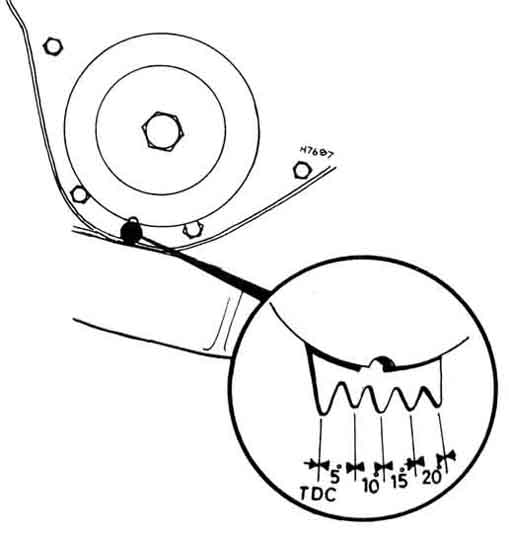 Several different arrangements over the years, but confusion between the WSM, Haynes and what is found in the wild. Prior to the 18V in 1971 the marks are always below the pulley, on the 18V they are above and angled towards the alternator so they can be viewed while twisting the distributor.
V8:
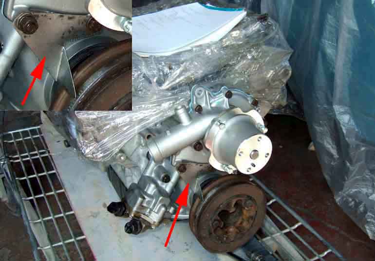 The markings are on the pulley, both BTDC and ATDC, with a single pointer. However replacement front covers don't have the tapped holes for the original pointer, so a new one has to be fabricated attached by two water-pump bolts.
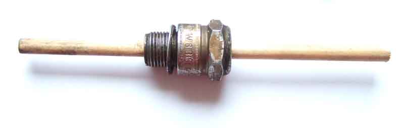 The accuracy of the timing marks can be checked, and the V8 pointer set correctly, with a depth-gauge such as this. The centre is knocked out of an old spark plug and a rod similar to this length of dowel inserted, such that it is a sliding fit in the plug body. Basically you set the rod such that the rising piston on, say, the compression stroke contacts it before TDC, and make a mark on the pulley adjacent to the timing pointer - using the TDC pointer on 4-cylinder engines. Then do the same on the expansion stroke, but turning the engine backwards until the piston contacts the rod after TDC and make another mark, and TDC is between the two marks. But because the plugs on MGBs are angled relative to the top of the piston I wouldn't like to fix the dowel in position and turn the engine until it is stopped by the dowel for fear of breaking off the dowel inside the cylinder. If a metal rod was used I'd be concerned about scratching the top of the piston, so I've opted for a sliding rod. Make one mark on the pulley before TDC, position the engine there, and push the rod down to contact the piston, and make a mark on the rod. Now withdraw the rod so you can advance the piston beyond TDC, and make fine adjustments to the engine position lifting and pushing the rod each time, until it goes in to the same mark as before. Now make the second mark on the pulley, and again true TDC is exactly between the two.
Vacuum Gauge February 2013
 A vacuum gauge can have three roles:
A tuning aid
A diagnostic aid
An aid to economical driving
The first two only need the gauge to be connected as and when required, the third requires permanent connection and mounting in the cabin where you can see it safely.
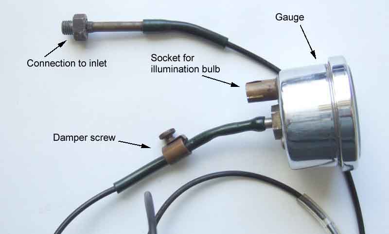 For all three it needs to be connected where it can get as balanced a reading as possible from all four cylinders and both carbs. The MGB has a large-bore balance tube in the inlet manifold interconnecting all of these, so it could be mounted as centrally as possible on the manifold. Depending on era and market, there are a number of tapped holes in the manifold, some with blanking plugs, some (particularly North American spec) with emissions related stuff screwed into them. If you have a free, centrally mounted blanking plug then this is the best candidate for a fitting for the gauge. My gauge came to me with a threaded brass tube (2BA), so I simply tapped a hole for that in a central blanking plug, which means I can switch between the modified and standard plug at any time. However a slightly off-centre plug may result in a slightly different signal from cylinders 2 and 3 as compared to 1 and 4 which could cause confusion in diagnostic mode. You would get a more consistent signal by tapping into each carb to manifold spacer, and teeing the two together. If you chose the manifold route the MGB had various adapters that fitted into the manifold from time to time, like for the overdrive vacuum switch, gulp valve, PCV valve and anti-runon system, you will have to consult the parts catalogues for which one will best suit your manifold. Don't use the crankcase breather port on later SU and Zenith carbs suitable as that gives a relatively constant low level of vacuum regardless of throttle opening or revs, except when actually moving the throttle. Many carburettors including SUs have a vacuum port, usually for connecting vacuum advance, but they show zero vacuum at idle so again aren't suitable for diagnostics and are normally only on one carb. Some after-market carbs may have a port that shows vacuum all the time, which would be fine for a single carb, but they will need to be Teed together for multiple carbs. The Zenith has an EGR port, and you might be tempted to use that, but it is the same as the vacuum advance port on earlier carbs i.e. it shows no signal at idle.
A tuning aid: My REDeX gauge came to me with instructions for all three roles, and those for tuning were probably the most beneficial. There are sections on both carburettor and timing adjustment, but as I've always used it with SU carb-equipped carbs I've always found the standard instructions for setting those up using the Mk1 ear and lifting-pin have been better than anything else. All you can do is turn the jet for the highest gauge reading, which coincides with the highest rpm i.e. you can hear it anyway, but that is only the coarse setting for an SU, the fine setting needs to be done using the lifting-pin. It's for timing where the vacuum gauge has been most beneficial.
Even when these engines came off the production line, they differed in many aspects. All the components have tolerances, and depending on which side of 'ideal' each of those tolerances are can cause one engine to vary significantly from another. One of the things that varies from engine to engine for a given type is the onset of pinking, i.e. how much advance a particular engine can take at a given rpm, throttle opening and load. The manufacturers are aware of this of course, excessive pinking can cause engine damage, and so they choose a 'worst case' scenario for the setting of timing advance to avoid pinking, plus a safety factor. What this means is that some engines can benefit from more advance, giving them better performance and economy, without any risk at all to the engine. Others may benefit little or none if they are at the 'other' end of the scale. I've had engines that fall into both categories, a new 1973 Marina fell into the former, and my 1973 MGB roadster (bought in 1990) into the latter. I could run the Marina with 2 or 3 degrees of extra advance, making a noticeable difference to performance. As a new car I was having it serviced by the dealer to maintain the warranty, and it always came back running like a dog as they reset the timing back to book, of course. However with the roadster I found I could get virtually no more advance with the gauge over the book figures, so after that I always stuck to book. That was on leaded. When we changed to unleaded it pinked significantly at book values and had to be retarded a degree or two even with the higher 97, and later 98 and 99 octane grades. If I had to use 95 octane it had to be retarded several degrees, with very noticeable reductions in performance, and increase in temperature gauge readings. Running-on also got very much worse on unleaded, so much so that I had to come up with an enhanced form of anti-runon control, as the after-market valve that was available at the time used as recommended had no effect on it at all. This era of MGB engine seems particularly prone, I well remember a club run up Shelsley Walsh hill-climb where cars around this age were clattering away like billy-oh, earlier and later less so.
On to the practicalities. You adjust the gauge for a higher sensitivity than normal, so the needle is trembling at idle, then slowly advance the timing until you start to see occasional little downward flicks of the needle. Retard very carefully until they just stop, note the reading, then retard a further 3/4 in Hg. That should now be the ideal timing for your engine and fuel.
However! Our engines that can easily be 40 years old with worn components, sundry replacements to various standards, and dare I say 'bodges', that change the characteristics of the engine through the rev range compared to how they were when the engine was new. You may well set it correctly for idle, but further up the rev range the timing can easily be advancing either more or less now than when everything was new, which means the timing is not correct off-idle. If it is advancing more, or the engine has a greater propensity to pink for some reason, you will need to retard a little. And if it isn't advancing as much or has a lesser propensity to pink than originally, then you won't be getting the best out of it. For that reason the only practical way to get the best out of your engine as it is now - without spending a lot of time and money on a rolling road fiddling with springs and weights - is to use your ear. Start at book, or by using the vacuum gauge, by all means. But then on the road (in a safe location!) floor it between 30 and 50 in top gear and listen for pinking. Haynes says to adjust until just the faintest trace of pinking is heard, but I suspect many won't want even that. Note the resulting static and dynamic figures for future reference. Another thing to bear in mind is terrain. If you adjust in Lincolnshire then go touring in Wales, the Lake District or the Scottish Highlands you may well find you have significant pinking. This brings the 25D4 distributor back into its own, being able to adjust the timing a couple of degrees each way using the vernier wheel. For that reason set the timing by ear with the vernier set appropriately, i.e. if on flat terrain then put it towards the advanced side so you have plenty of scope for retarding for hilly terrain. You could do the opposite if setting it for hilly terrain, but I doubt many would bother to advance it for touring in flatter areas.
A diagnostic aid: As far as diagnostics goes I've rarely had to use it for that purpose, the few times I've had problems I have mostly used other methods. So the best I can do is refer you to sites such as IWEMA Enterprise and Second Chance Garage, although in my experience the scenarios depicted in the second one are much clearer than they would be in real life. Again the sensitivity of the gauge has to be increased to give more needle tremor than would be normal if you had the gauge permanently installed in the cabin.
An aid to economical driving: The general aim to keep the needle as high as possible. Sensitivity is normally slightly reduced, to get near full needle movement, but damped i.e. no tremor or rattling. Not only is rattling irritating but it will rapidly wear the gears inside the gauge between the Bourdon vacuum tube and the needle. It might prompt you to use slightly less throttle for acceleration up to cruising speed, but more importantly once at cruising speed you will normally find that you can back off the throttle a smidgen to get a higher gauge reading, without any apparent loss in speed. This is counter-intuitive, but believe me it works, and after a time it becomes second-nature so that you do it anyway even if you don't have a gauge fitted. I credit techniques such as those with being able to get 40+mpg in the roadster on a good steady run, and 30+ in the V8, when period road tests claim the average mpg for the 4-cylinder car is 27mpg!
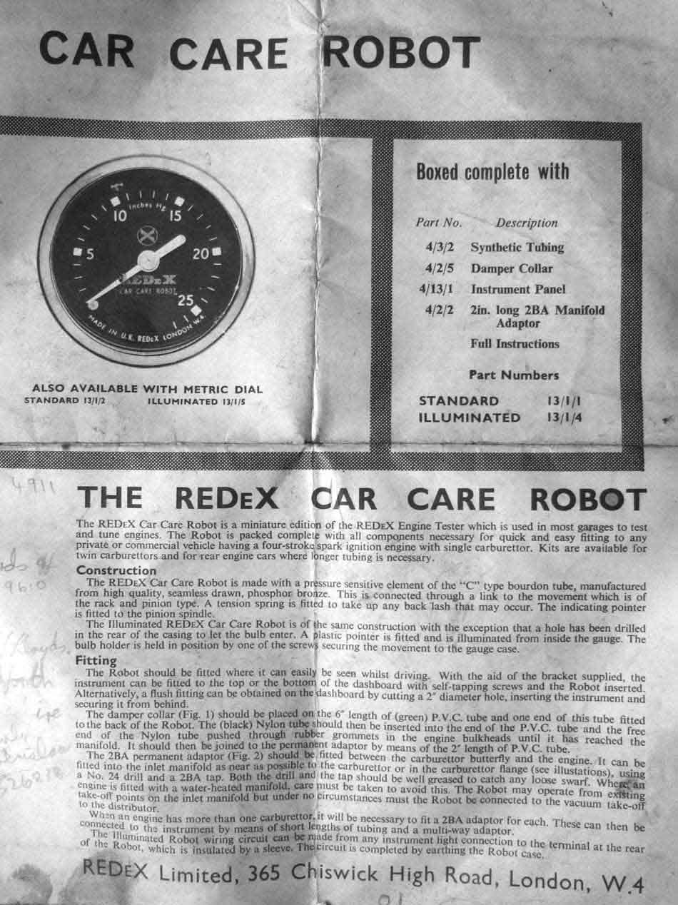 Instructions for the installation and use of my REDeX gauge.