


Types
Mounting
Connections
Alternatives/Replacements
Repolarising a Dynamo
Charging System Basics
Ignition Warning Light and Charging Theory
Dynamo Control Box
Alternator Operation
Testing Output
Trickle-charge current
Charging Faults
Alternator Brush Replacement
Alternator Harness Plug Clip
Pulleys
Fan/drive belts
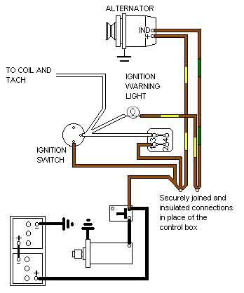
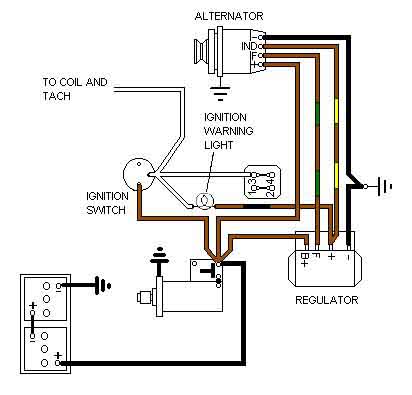
Converting Dynamo to Alternator
Converting 16AC Alternator with separate regulator to later alternator with integral regulator
'One wire' Alternators
January 2021: A dynamo does not output AC as Ant Anstead said in the Wheeler Dealers episode on the TR4. Both dynamo and alternator output DC at their terminals, they just use different methods internally to do so. A dynamo generates DC internally and outputs that directly, an alternator generates AC internally but rectifies it to DC before outputting it. What Ant Anstead held up is the 'control box' which regulates the voltage and current the dynamo outputs to charge the battery and run the cars electrics, using relays and resistors. The first alternators used on the MGB - the 16AC used on early Mk2s - also had external regulation, albeit electronic instead of relays and resistors, but after that that 16ACR, 17ACR and 18ACR had internal regulation and all modern alternators (except possibly very specialised applications) will be the same.
A dynamo and separate control box were used on Mk1 MGBs. The first MGB alternators (MkII models in 1967) were the 16AC (remote regulator) and 16ACR (integral regulator) which are rated at 34 amps. It was changed to the 17ACR in February 1973 and finally the 18ACR in about June 1976. There is conflicting information about the output rating of these latter two, some sources say the 17ACR is 36 amps and the 18ACR 45 amps, others say the 17ACR is 43 amps and the 18ACR 45 amps. 43 or 45 amps ought to be sufficient for factory loads, the V8 has a Delco 46 amp alternator and that is sufficient to keep the battery voltage above 12.5v even with headlights, twin cooling fans and the heated rear window running, and at idling speeds. The problem is that people fit voltmeters wired to the green circuit, which can be a couple of volts lower than the solenoid i.e. battery voltage, then get paranoid. It's battery voltage which is important, and any volt-drop between there and the green circuit is down to ageing connections, and the best alternator in the world isn't going to cure them, although it may cover them up.
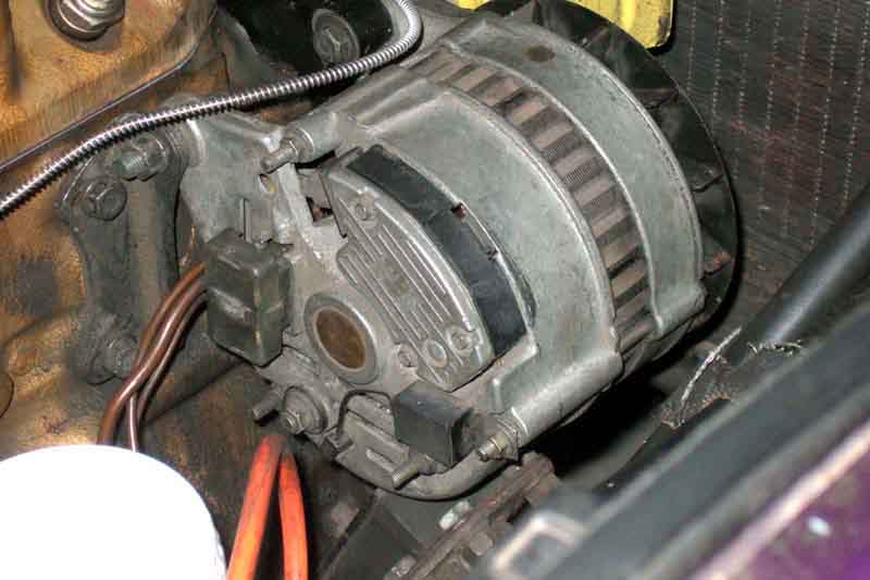
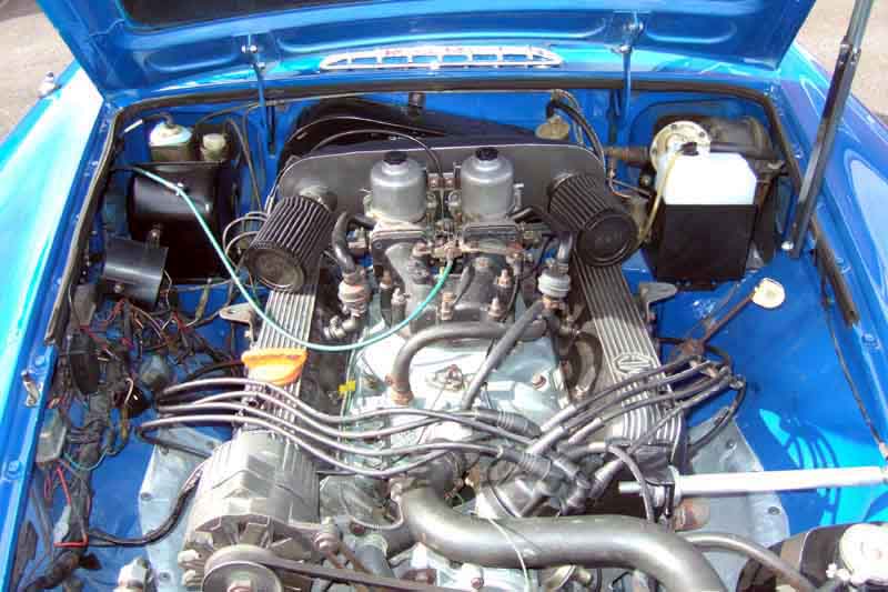 I had briefly wondered why an AC/Delco was chosen for the V8 when it has almost the same output capacity as the later Lucas items. It was only during a discussion with someone about alternators for a V8 conversion that it became clear - the Lucas alts are too long to fit in the factory position as the rocker cover is in the way! It wasn't a problem for Costello as he swung the alternator out from the engine, but the factory fitted the MGB V8 filter high up on the inner wing which precluded that. Hence a shorter alt that would fit directly in front of the rocker cover. Only just though, as the harness plug has to be wiggled off at an angle.
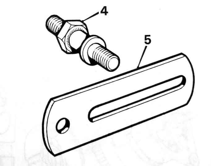 With the top front mounting bolted to an ear on the water pump, there is an adjuster link on the lower front mounting. Prior to the 77 model year both dynamo and alternator used a flat link 12H67 or 2A497 and a pillar 2A128 on the engine front cover. For 1977 on a different link was used - 12G2627, which the Parts Catalogue (and a couple of supplier drawings) seems to show is cranked, without the pillar. However Googling 12G2627 shows a flat link, albeit curved with a curved slot, so the pillar is still needed. On older alts the lower adjuster ear is threaded, so the bolts clamps up the link directly, then a locking nut is fitted for security. However a replacement alt purchased by John Wallace is not threaded, so really double-nuts should be used, or at the very least a stiff-nut.
Both front and adjuster link mounting points may need spacer washers to correctly align the alt pulley with the water-pump pulley.
Rear:
 Both dynamo and alternator use their own versions of an angle bracket to attach a single mounting point on the rear end-plate to two bosses on the block. Early blocks only had two for the dynamo, whereas later blocks have one pair for a dynamo and another pair further forwards for an alternator. After-market adapters are available to mount an alternator to an early block which only has the rear-most pair of bosses. Alternators should have a sliding (interference fit) bush in the rear ear which automatically takes up the correct position as the front and rear bolts are tightened. The bracket is also adjustable to the block, and that should be set such that the bush is somewhere between its two extremities. If right at one end then as the bolts are fully tightened the ears could be under a bending stress risking fracture.
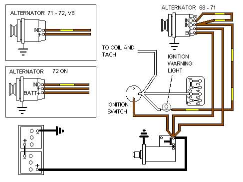
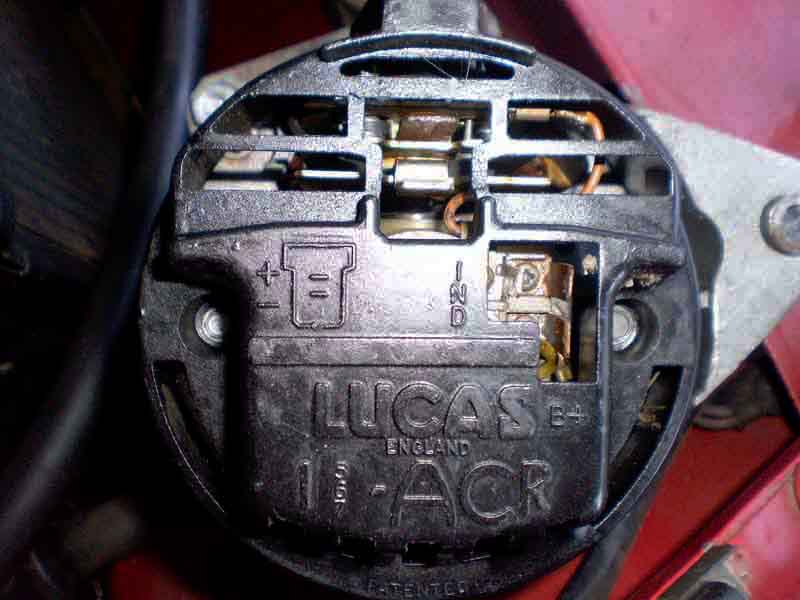 There are several different connection arrangements for Lucas alternators over the years ranging from 4-pin of the 16AC with remote regulator (best avoided for a conversion), then a 5-pin using two connectors on the early internally regulated 16ACR and finally a 3-pin single connector for other 16/17/18ACR variants. 5-pin/two plug systems have two Indicator spades in one of the connectors which are linked together by a loop of brown/yellow wire in the plug, possibly to protect the alternator if the engine is run with the IND/B+ plug removed. 3-pin have two variants - one with two large spades side-by-side and a single standard-sized spade to one side, and another with a single large spade in the middle and a standard-sized spade either side of it, one possibly with chamfered corners. Where there are two large spades both are outputs (+), with the standard-sized spade being for the indicator wire (IND). With the other type the single large spade is the output (+), the standard spade is for the indicator wire (IND), and the one with the chamfered corners is for the voltage sensing wire (B+ or BATT+).
The B+ (or BATT+) voltage sensing terminal is wired back to the solenoid with a standard gauge brown wire. This is used to sense the voltage at the solenoid rather than the alternator for voltage regulation purposes, and would ensure that under high current conditions any volt-drop occurring in the main output wires (thick brown and black) between alternator and solenoid/body is ignored and the voltage at the solenoid (and hence the battery) is maintained at the correct level, this system is called 'battery sensing'. This was the case in the 5-pin 2-plug 16ACR from 69 to 71.
Initially the 3-pin single-plug alternators used machine sensing (i.e. the correct voltage is maintained at the alternator terminals, but could be lower at the solenoid and hence battery under high current conditions) with just a single thick brown and a standard gauge brown/yellow in the alternator plug with the third position in the harness plug empty. This is a '2-wire' alternator, seen on a 1972 model.
Possibly because of problems with low battery voltage for 1973 the Workshop Manual diagram shows the alternators have reverted to battery sensing again having 3-wire alternator wiring. Clausager states that a new version of the 16ACR with modified regulator and surge protection was provided in March 72, and is how Bee a 73-model built September 72 is wired with an additional standard-gauge brown in the alternator plug wired back to the solenoid as before, and seems to have remained the case up to and including the 77 model year at least.
Clausager states the 17ACR was fitted from February 73 so higher output, possibly associated with the GT HRW having being made standard equipment. This is a 3-wire alternator, but can be used with a 2-wire harness by connecting the third spade to the output spade in the alternator plug. A '2-wire' alternator i.e. one with two large output spades can be connected to a 3-wire harness as-is i.e. each brown wire to either of the large output spades, although the harness plug may need to be changed to fit the alternator.
The final variation was the 18ACR. Clausager says the exact change point is unavailable, but thinks it was from June 76, borne out by the Parts Catalogue which shows the 18ACR being used before September 76. The schematics get confusing here, with UK 1979 from the WSM and 'later' models for both UK and North America indicating it had reverted to machine-sensing with two thick brown wires from the two large output spades to the solenoid. This would give increased current carrying capacity and lower volt-drop now cars had electric cooling fans, offsetting the loss in voltage caused by the regulator sense terminal moving from the solenoid back to the alternator again, and despite the three wires is effectively a '2-wire' system. However JCR Supplies at one time showed this diode pack which is the 3-wire battery-sensing type, and I have seen the harness plug on a 78 which does match that with thick and standard brown wires rather than two thick. However they said it was for an 18ACR, which other sources indicate should be machine sensing. They also showed one with the two large spades i.e. the Euro plug, correctly described as machine sensing, but saying it is for 15/16/17ACR.
October 2014:
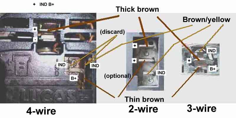 Click the thumbnail for details on converting between 4-wire, 3-wire and 2-wire alternators.
And to beat it to death, put a bullet in its brain, and hang, draw and quarter it, there are additional changes to the above in the Parts Catalogue:
- The original 16ACR as detailed above - part No. 37H 4194
- A different 16ACR in Jan 71 - 37H 6983
- The modified 16ACR as detailed above in March 72 - 37H 7503
- The 17ACR as detailed above in Feb 73 - 37H 7959
- A different 17ACR (no date) - 37H 8208
- An 18ACR (no date, but prior to September 76 and used to the end of production) - AAU1013
'Two browns' (what a terrible thought) wiring will cope equally well with both battery sensing and machine sensing alternators, but battery sensing alternators must have the 2nd brown wire, or at least a link in the harness plug between the + and B+, to operate correctly. In addition to the brown/yellow Indicator wire a friends 72 only has one brown (large), my 73 has one large and one smaller brown, and another friends 74 is the same, so those at least conform to the above. For completeness my 75 V8 (AC-Delco) uses the same plug, both large spades are output terminals, however only one is wired (as per the factory schematic) with a heavy gauge brown, the other is unused (and has allowed me to use it as a direct output to the cooling fan relay).
So some care needs to be taken to determine just which type of wiring, plug and alternator you have when making changes, even swapping alternators which take the same plug. If by looking at the two large spades on the alternator you can see they are clearly connected together, then you have a machine-sensing alternator and can use either or both large spades for the output. But if the two are clearly insulated from one another, then you have a battery sensing alternator. On these you must have a large gauge brown wire on the output spade at the very least, and a smaller gauge at least on the sense terminal. If in doubt as to which you have, it may be possible to determine by voltage measurement. Turn all the electrical loads on you possibly can, alternator plugged in, engine running at a fast idle, then connect a voltmeter between the two large spades. If you can measure any voltage between the two (may only be in the order of tenths of a volt) then you probably have a battery sensing alternator. If there is zero volts between the two large spades, then you probably have a machine sensing alternator. Or simply provide large gauge brown wires to both large spades to cover both eventualities, and get the benefit of a lower volt-drop under high-current conditions if you have a machine sensing alternator.
Tip: If you carry an alternator as a spare at any time, then it's a good idea to make sure it already has a pulley fitted. The large nut is very tight and makes it very difficult if not impossible to remove the pulley from a failed unit as there is no easy way of holding the rotor still (except perhaps by wrapping a fan-belt right round the pulley and gripping it firmly). If your spare alt has a pulley, then compare the size with what's on the car. If it's the same size then all well and good. If it's a different size then check now by trial-fitting that it is compatible with your fan-belt! And remember, if the pulley is smaller the alternator will rotate faster than normal, so you may want to limit engine revs a little to avoid over-revving the alternator. If it is larger then it will rotate slower, so you may find the engine needs to be revved a bit higher before it starts charging, will stop charging sooner as the revs fall, and it may not charge at idle. The charge voltage and current during normal driving will also be lower than usual, but if you keep the revs up and/or the electrical load down it should still charge well enough to get you where you are going.
Alternatives/Replacements April 2021
We scrapped a Metro years ago but I kept the alt which is an A115 45 amp. A direct replacement on the roadster, even though the pulley is slightly larger so rotates slower which reduces output, but the belt still fits, and it's good enough to carry as a 'get you home' spare. As it happens the roadster came to me with what looks like an A127 (metal end-plate instead of plastic on the 16/17/18 ACR and A115 types) of unknown output, which are available in 45, 55 and 65 amps with standard Euro plug spade terminals (as mine is), and 70 amps with stud output terminal. These are available from various Mini parts suppliers (including Moss), and given that the Metro item seems to be a direct replacement, these Mini items may be as well if you have additional loads and need a higher output. However given the availability of a universal 16/17/18ACR at 55 amps as recounted above maybe that is a better bet even at the cost of the faff with the belt, and it would be worth trying a 10925.
Whilst fitting the 55amp round at my pal's house his neighbour came round asking if we had any use for an 18ACR from his TVR days. Pal didn't want it so I had it, thinking I might be able to juggle things around and end up with a spare for the V8 as well. It's too long for the V8 which has the rocker cover immediately behind it - 5.5" as opposed to 4.6" of the AC/Delco. But it is a direct replacement for the A127 the roadster came with so was fitted and tested and gives good output, which makes the A127 available as a spare for the V8.
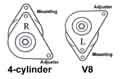 Whilst both alts are on the same - driver's - side of the engine 4-cylinder cars have the mounting ears on top and the adjuster link underneath, but the V8 is the other way round. This makes the V8 a 'left-hand' as opposed to the 'right-hand' of the roadster. But by removing three through-bolts you can rotate one half of the casing with respect to the other and perform a 'gender reassignment'. That needs the pulley and fan to be removed as the fan covers the heads of the bolts, which was where we came 'unstuck' with the 72 MGB above. Thinking we would need to transfer them over as some sources showed a 'bare' alt, but the pulley was stuck fast onto the shaft although the nut itself came off easily with a chatter-gun and one hand holding the old belt wrapped round the pulley. It did eventually come off, but not before a piece of the cast pulley broke off, meaning we had to get one with fan and pulley already fitted. The Woodruff key also took some shifting. But this nut came off with my air-gun and belt as before, and the pulley and fan just fell off and no provision for Woodruff key. After that altering the case was easy, and a trial-fit before refitting the fan and pulley showed that it was a goer, so refitted the original AC Delco. The belt has always been too long on that - right at the end of the adjuster link, and while it was off I noticed the part number was VS1138, indicating that it was 1138mm long instead of 1125mm as it should be. I have a note that I bought a spare on getting the car, fitted when the one that came with the car frayed (and pulled a coil wire off ...). At that time I bought a new 11125 which has been in the back ever since, so that went on now and is the correct size leaving a bit of adjustment left. So another 11125 bought as a carried spare, and the 1138 kept 'just in case' at home. Trial fit both to check the belt fits, it works, and the pulley is aligned correctly.
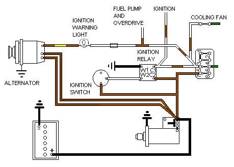
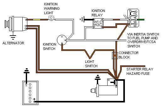
Ignition Warning Light (aka 'Idiot Light') and Charging Theory Schematics ![]()
Change to LED?
Why 'Idiot' light? I don't know, but it seems to be an Americanism (that is, it's Americans that seem to use the term, not that Americans are idiots as one seemed to think I meant ...). The only thing I can think of is a point of view that says "Only an idiot would need a warning light telling them the ignition was on." Which shows a complete misunderstanding of the purpose of the light, so who's the idiot now? However someone else said that he has heard the oil warning light (provided in lieu of an oil pressure gauge) referred to as the 'idiot' light, because only idiots ignore it when it comes on then seize their engine. But another view has it that even idiots should be able to understand when a warning light comes on, whereas you need intelligence to understand a gauge. So maybe, in terms of the ignition warning light, only an idiot ignores it until the battery goes flat, and as Jochen Beyer has pointed out the ignition warning light also lets you know your fan-belt has broken before you boil your coolant out.
 The ignition warning light always had two wires connected to it which must be insulated from earth as at various times one side receives 12v from the ignition switch and the other side 12v from the alternator or control box. Most of the other bulb holders on CB 4-cylinder cars only need one wire as they can pick up an earth from being plugged into to metal panel or instrument case. V8s and RB 4-cylinder cars have the other warning lights with two wires as well as they are fitted in plastic panels so need a wired earth.
The warning light is like a pair of balance scales between the ignition circuit and the charging circuit, and that is how it is connected - from the white of the ignition circuit, through the bulb, and to the dynamo/alternator via the brown/yellow. (Note that the lamp-holder is unique in that it has two wires - one to each side of the bulb - and the body of the holder should not be connected to earth like the panel and main-beam lamps are.) If both circuits have the same voltage then there is no potential difference across the bulb and it will not light. This is irrespective of whether there is 0v on both circuits (ignition off, engine stationary) or 12v (actually around 14v when charging) on both circuits (ignition switched on and engine running and charging). If the two circuits show a potential difference i.e. ignition switched on but engine stationary, or ignition switched on and engine running but not charging, then the lamp will light. This latter condition is a fault (and incidentally the main purpose of the light) which should be investigated before you get stranded. You may also note that when you switch off the ignition but while the engine is still spinning the ignition warning light glows again until the engine stops. This is because the charging system is still outputting while the engine is spinning down, so outputting 14v to the brown/yellow, but with the ignition off there is no longer any voltage on the white. By itself that wouldn't cause the warning light to glow, but as there are several other circuits also powered from the white, each with their own path to earth, current from the brown/yellow passes through the warning light bulb and these other circuits to their earths, and that is enough to make the light glow, until the charging system stops outputting. It is this feature that gives rise to the "won't switch off!" problem that can affect 1977 and later North American spec.
At the simplest level, a glowing warning light tells you that the ignition is switched on but the dynamo/alternator is not charging. It may be obvious that the dynamo/alternator isn't charging if you haven't even started the engine yet, but the beauty is that you can see the warning light itself is working. So if the engine is running and the charge does fail at some point, then you have a very good chance that the warning light will come on and tell you about it. On alternator-equipped cars the warning light acts as a priming system to start it charging from about 1000rpm. Without the warning it may need to be revved to several thousand rpm to start, and new alts out of the box may not do that. Dynamos are self-priming as below.
Faults: By which I mean not glowing when it should or glowing when it shouldn't.
Change to LED? The short answer is no. As stated above the warning light on alternator-equipped cars is used as a primer to start it charging, using the current through the incandescent bulb. If changed to an LED the current is reduced to a fraction of its previous value and won't allow it to start charging at the normal point. The warning is also part of the on-board diagnostics, and current can flow in either direction under various conditions. An LED only glows with current flowing in one direction - unless you go to the bother of installing it with a full-wave bridge rectifier. Although this effect is not an issue with dynamos there is another aspect relating to the warning light acting like a pair of balance scales. It is inevitable that there will be some differences in voltage between the ignition supply and the dynamo/alternator output and this difference in voltage increases as the demand for current goes up i.e. lights, wipers, heater fan and so on are turned on. Because an incandescent bulb is relatively insensitive to small voltages it will not glow, unless there is a fault resulting in a bigger difference in voltage then there should be. But LEDs are much more sensitive to small voltages and will glow when incandescents wouldn't, including when there is no actual fault as such. Even some suppliers will tell you not to fit one in this position.
With the exception of RHD cars from 1977 on with the ignition relay, the white for the warning light always comes off the ignition switch. On RHD 1977 and later cars it comes off the output of the ignition relay which starts off white/brown, then changes to white at the multi-way plug behind the dash. See ignition schematics for more info.
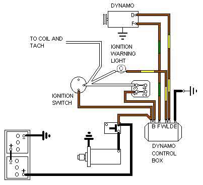
On a dynamo system the warning light brown/yellow is connected to the dynamo output at the control box and hence has a low-resistance path to earth to light it when the ignition is turned on. The initial excitation for the dynamo field always comes from its own residual magnetism, which is why you have to 'flash' the field terminal to battery when you install a new dynamo or when you are converting from one polarity to another. NEVER, I repeat, NEVER flash an alternator's terminals to battery. This residual magnetism results in a dynamo output of a couple of volts, which is passed through low-resistance windings on the cut-out and current regulator relays in the control box to the field winding. This voltage now causes the dynamo to output its full voltage, which operates the cut-out relay to connect the dynamo output to the battery so charging it. The cut-out relay has a normally open contact which disconnects the dynamo when the engine is stopped, or the output voltage drops below a certain level. In fact it usually releases at idle, lighting or flickering the warning lamp. If this did not happen the battery would rapidly discharge through the dynamo, which would be acting like a motor trying to turn the engine. The cut-out relay has two windings, one of which ensures the relay releases as the voltage falls. IMPORTANT NOTE: If you manually operate the cut-out relay with the engine stopped it will latch in, connecting battery voltage to the dynamo, which will try to turn the engine. This passes a high current through the control box and dynamo which will burn them out in quite a short time.
Because it has connections to both the ignition supply and the alternator or control box the bulb holder is a special in that it always has two terminals which are insulated from the body of the bulb holder so cannot short to an earthed metal panel. Various other bulb holders also had two terminals at various times - Mk1 indicator tell-tales for the same reason as the ignition warning light, V8 and RB indicator tell-tales and main-beam warning lights as they are fitted to a plastic panel and so need a wired earth.
Dynamo Control Box April 2013
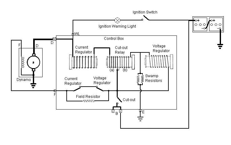 Click the thumbnail on the left for step-by-step information on how the control box does what it does. Considering its technology is so old its method of voltage and current regulation is really clever - a form of time-division multiplexing if you want to be technical. Basically when the battery voltage rises above a certain point the voltage regulator relay will operate. Its contacts (normally closed) open, introducing a resistance into the field circuit. This reduces the voltage at the field winding, which reduces the output voltage and current, and hence the charging current, allowing the battery voltage to fall back slightly. But it doesn't operate just once, oh dear me no, it is usually operating and releasing rapidly all the time unless the battery is significantly discharged. When the full dynamo voltage is connected to the battery, the battery voltage can't rise immediately, but takes a period of time. As it's voltage rises so does the voltage across the voltage regulator relay, which eventually operates. This reduces the dynamo current and voltage, but again the battery voltage can't drop instantly, but takes a period of time. It's only when battery voltage has dropped below a certain point that the voltage regulator relay releases again, so connecting full dynamo voltage and current to the battery again. The really clever bit is that when the battery needs charging it takes a relatively long time for its voltage to rise enough to operate the voltage regulator relay, and a relatively short time for the voltage regulator relay to release again. The result is a relatively high average charging current, to rapidly recharge the battery. As the battery becomes charged the time taken for the voltage regulator relay to release each time increases gradually, and the time taken for it to operate again reduces gradually, giving a lower average charging current over time. The average current as seen on a graph has a relatively steep rise initially when recharging starts, gradually flattening out as it approaches a horizontal 'fully charged' line (ranging from 14.9 to 15.v at 10C to 14.3 to 14.9v at 40C), until it just touches it, at which point just a trickle charge is being put into the battery. In practice, unless the battery is significantly discharged, the voltage regulator relay operates and releases very rapidly, this can be felt as a rapid vibration of the relay armature as it is lightly touched with a finger-tip, and a continuous electrical arc can be seen at the contacts.
The current regulator relay operates on a similar principle, but it only comes into play when the maximum design current of the dynamo is reached. The relay operates, introducing the same resistance into the field circuit, which again reduces the field voltage and hence the output current, to protect the dynamo against overheating and damage. This reduction in current causes the relay to release again, so giving full current, which causes the relay to operate again and so on, giving an average current over time as before. The system is designed such that this average current (19 to 22 amps) is the safe current for the dynamo. With large non-original electrical loads connected to the system it will be the current drawn by these that will cause the current regulator relay to operate to protect the dynamo. The loads are still connected of course, and so is the battery, and it will be the battery that will be supplying them then, at least partially, so gradually discharging it, even though the engine is running and the dynamo is operating correctly.
I've heard a claim from someone who studied the workings of the control box at college (many years ago!) that there is a weakness in the system in that if the battery is less than half charged the characteristics of the control box are such that the battery will never recharge, and you would have to recharge it using a charger before you could use it normally again. Personally I can't see it, the cut-out operates independently of the battery voltage, and even if that then tries to take so much current that the current regulator relay operates, the dynamo is still going to be delivering some voltage. As long as that is more than battery voltage then the battery will charge. Subsequently perusing the Lucas Fault Diagnosis Manual I found the statement that if a battery has been fully discharged, the on-board charging system will never put back more than half the original capacity, so I think that is where the 'half charged' thing comes from. Boost charging will be required to put back the full charge, and this applies to cars with alternators more so than dynamos as the regulated alternator voltage is less than the dynamo regulated voltage under most operating conditions. It's particularly relevant to cars equipped with electronic alarm systems, including modern cars, where these are used infrequently i.e. there is a constant trickle discharge from the battery.
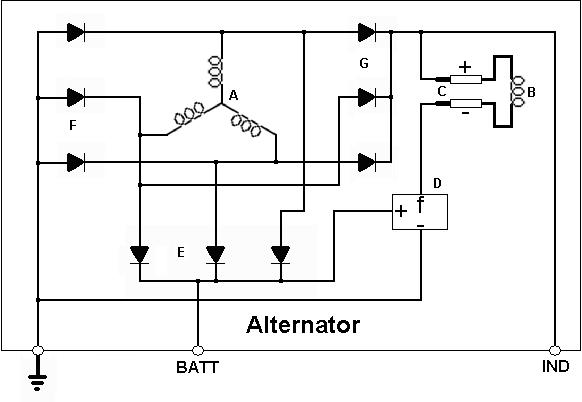
 By contrast an alternator system takes much less explanation - unless you get into the theory of semiconductors! In an alternator the warning light brown/yellow connection is connected to the field windings, which because they are relatively low resistance and connected to earth, offers an earth-path to the bulb to light it when the ignition is turned on. So it is the warning light current through the bulb and the field windings which generates the initial excitation for the output windings. This generates an initial output voltage, which is fed back to the fields as well as the output terminal by a set of diodes, to give the full excitation voltage and hence the full output voltage. It is at this point that the bulb has full system voltage on both sides and therefore extinguishes, which is usually at about 900rpm. With the alternator charging, as the engine is slowed the alternator output voltage drops, and hence the field excitation current, until at about 600rpm charging suddenly stops and the warning light will glow.
From this it can be seen that the ignition warning light is necessary to give the alternator its initial excitation, and some schematics do show a resistor wired across the warning light to ensure that this initial excitation current is available even if the bulb has blown or is removed. However, I have never known of this resistor being provided in practice, and also in practice a used alternator has a little residual magnetism that is usually enough to 'kick-start' it into charging, although the engine may have to be revved to 2000 or 3000 rpm before this starts happening. Once it has started charging, it will charge normally i.e. down to about 600rpm as before, but then need to be revved to 2k or 3k again to start charging again. A new alternator just out of the box may not have this residual magnetism and so may not be able to kick-start itself, in which case the ignition warning light circuit is essential. ON NO ACCOUNT should you try to generate this magnetism by 'flashing' the alternator connections across the battery like you would polarise a dynamo, you may well blow the diodes or other electronics.
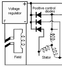
The voltage regulator is a sealed electronic module which constantly varies the voltage fed back to the field windings from the output, according to the voltage of the output - i.e. a closed-circuit feedback system. There is no current regulator circuit as such, the books say that the inherent design of the alternator is such that current is automatically self-regulating. This is possibly from the thickness of the output windings and hence their resistance (higher output units having thicker wires), that being all that is required as unlike a dynamo an alternator has its output windings attached to the case, hence no brushes or commutator to limit current. It does mean that an alternator naturally generates an alternating current in its output windings (3-phase in fact), hence the requirement for a network of diodes to convert this to pulsed direct current at the output terminals and field windings.
 My Leyland Workshop Manual has a schematic of the 16AC alternator charging circuit which shows a resistor connected in parallel with the warning light, but none of the full schematics show this, and as far as I know one has never existed in practice. Apparently the RV8 schematic also shows one, but Nic Houslip has confirmed with one of the engineers that worked on the RV8 that it doesn't exist on that either. If you Google 'ignition warning light resistor' you get a lot of chatter about whether this resistor exists or not. One can see that with alternators if the warning light blows, then theoretically there is nothing to start the alternator charging (although as indicated above used alternators at least will start charging when revved to about 2k to 3k, then charge normally after that down to about 600 rpm). On cars with a dynamo and control box the warning light is purely an indicator, it has no priming function, as the residual magnetism in the dynamo makes it self-priming. A number of comments are incorrect, some say it should be in series and not in parallel, and some cause even more confusion by talking about the use of LEDs in place of incandescents (what on earth for?). But it does appear that there are schematics for marques other than MG that also include them, and for a lot more recent models, for example BMW seem to have started providing this resistor from 1987. An interesting one is Bud Krueger's MG TD site where he shows pictures (reproduced here) of what he believes are original warning light holders for his car, with a length of resistance wire wrapped around the holder of both the ignition and low fuel warning lights. However Bud tells me they are in series with the lamps to reduce the brightness. The TD has a dynamo which as I say above doesn't need the warning light to start charging, and a low-fuel warning circuit wouldn't require a bypass circuit in any event.
Under normal circumstances, with minimal electrical load, you should have 14v to 15v on, say, the brown wires at your fusebox. As you switch on more and more electrical circuits you will take more and more current from the dynamo or alternator. As that approaches its maximum output current, the system voltage will start to drop, and when the system voltage drops to 12.5v you have reached the maximum capacity of your charging system. Any further increase in electrical load will reduce the system voltage below 12.3v, and some current will be taken from the battery. You can use this 'feature' - voltage dropping as current increases - to check the output of your charging system, either dynamo or alternator. You could put an ammeter in series with the dynamo or output wire, but most home-use multi-meters only go up to 10 amps which is less than half the output of a dynamo let alone that of an alternator, and connecting an ammeter to an alternator is not straightforward. It is easier to monitor the system voltage while gradually switching on more and more electrical circuits, and varying the engine speed, and seeing at what point the system voltage dips below 12.5 volts. Lighting circuits have stated wattages for all the bulbs which can be used to calculate current - add all the wattages together, then divide that by 12 volts to give amps. For example by turning on the parking lights of an MGB you can have four bulbs at the corners and four number plate bulbs all at 5 watts each and four 2.2 watt bulbs in the instruments, giving 48.8 watts in total, or 4 and a bit amps (North American cars with side markers have another four 5 watt bulbs or 1.7 amps). A pair of 45 watt dipped beams adds 7.5 amps, if you have a headlamp flasher and 60 watt main beams that will add another 10 amps. A pair of 21W brake lights will add 3.5 amps, as will a pair of reversing light bulbs, and all that totals 28 amps (30 amps for North America with side markers). A pair of 21W indicator bulbs adds 3.5 amps, and hazard lights with four 21w bulbs will add 7 amps, but of course these and the indicators will be flashing so their effect on the voltage will not be steady so making it difficult to read. However these can be added by bypassing the respective flashers to get a steady glow, and hence a steady effect on the voltage.
For dynamo-equipped cars i.e. with a 22 amp output capacity parking lights, dipped beams, brake lights, reversing lights and indicators take about 22 amps. For alternator-equipped cars these lighting circuits plus headlamp flasher and heater fan give 35 amps. On GTs the HRW adds about another 7 amps, although mine takes 9 amps as it is on a relay, and my V8 twin fans add another 10 amps. With all these there is more than enough load (54 amps) to overwhelm the 46 amp alternator. But don't expect to see the voltage drop below 12.5 volts at exactly the calculated load on your dynamo or alternator. Even if your circuits seem to be working well there are bound to be some unwanted resistances in switches and connections which will reduce the current taken by the circuits, which means you may be able to take more than the theoretical output of your dynamo or alternator and still be at more than 12.5 volts. However if the voltage drops below 12.5v at less than the theoretical figure, then either your dynamo/alternator is giving less output than it should or there are bad connections between it and the solenoid. So take another voltage measurement right at the dynamo control box 'B' terminal or alternator output terminal, and if that is more than about 0.5v higher then you have some resistance between the two measurement points which is limiting the maximum effective output.
The Workshop Manual quotes charge voltage for the dynamo at 3000rpm as follows:
20C/68F - 14.7 to 15.3v
30C/86F - 14.5 to 15.1v
40C/104F - 14.3 to 14.9v
For the alternator it quotes 14.3 to 14.7v, the closer tolerance due to temperature-compensated electronics. However some suppliers of replacement voltage regulators quote 14 to 14.5v for their products, and another quotes 13.6 to 14.4v. I remember reading some time ago that Mercedes had started using higher voltages to protect against premature battery failure, as the lower the voltage the less capacity the charging system will be able to restore. Lucas states that a battery having lost just 25% of its charge will never be fully recharged by the vehicles charging system - even at the higher of the above voltages, and a battery that has gone completely flat will only regain 50% of its capacity from the vehicles charging system, both situations requiring an external charger at a higher voltage and current for maybe several hours. All this came about from a pal finding that his car took several seconds of cranking to start from cold normally, and he never got more than about 14.1v at the alternator terminals, even after a 30 mile run, even revving the engine, but after being on a conventional trickle charger it fires up straight away. He wondered whether his voltage regulator was faulty, which led to finding the above figures for replacements. However Bosch regulators are available in 14.2, 14.6 and 14.7v flavours, and maybe as high as 15v, and it would be interesting to see if there is a higher voltage Bosch unit that would fit a Lucas alt. There are about 30 Lucas voltage regulator part numbers just for the 16/17/18ACR, and almost as many Lucas equivalent numbers for each Bosch regulator. One would have to try and match each Lucas number with each Bosch Lucas equivalent - patience required! It had occurred to me that perhaps one could modify how the existing voltage regulator was connected and so 'encourage' it to output a higher voltage. A diode would be the obvious way, these have a forward volt-drop of about 0.5v regardless of current, and if connected correctly should result in an increase of 0.5v in the output. Whilst looking for higher voltage Bosch units I came across someone with a similar problem as my pal, and had done just that.
Alternator Bench Test: For an alternator this is quite easy, but you have to be careful with a dynamo as it is very easy to exceed its maximum voltage and cause an internal fault.
For the alternator all you need is a 12v supply, a small bulb to simulate the ignition warning light, a voltmeter, and something to spin it such as a drill.
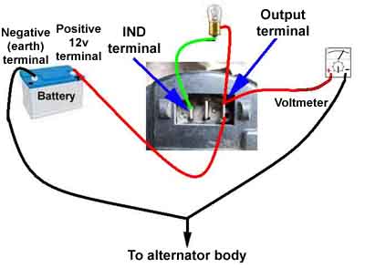 12v goes to an output spade (usually one of two large spades on the 3-pin connector on all but the earliest alts) and to one side of the bulb. MAKE ABSOLUTELY SURE THE POLARITY IS CORRECT OR YOU WILL SERIOUSLY DAMAGE THE ALT. The other side of the bulb goes to the smallest of the three spades where the output plug goes. Earth goes to the body of the alternator. The meter goes between the 12v supply and earth.
My alternators all have a 22mm pulley nut, and a long bolt through that with the head and washer inside the socket, and a nut and washer on the back of the socket, means the bolt shank can be clamped in the drill chuck.
The bulb should be glowing, set the drill to spin the alternator clockwise as you look at the pulley, and increase the speed. At some point the bulb will suddenly dim right down (but not go completely out) and the voltage on the meter will step up from 12v to 14v+, which indicates the alternator is now charging.
Note 1: The engine typically has to be spinning at 900-1000 rpm to start the alternator charging normally, and the alternator is spinning quite a bit faster than that. With my mains drill, multi-speed Bosch, on the highest setting, two of my alternators need the drill to be at nearly maximum speed before they start, and another one does not start to charge. With that alternator on a car the warning light doesn't go out until the tach shows 1100rpm, so my drill probably isn't quite fast enough.
Note 2: Unless you have 12v connected to the output terminal of the alternator when you spin it, when it does start charging it can generate a high voltage of 30v or more. This is why alternator-equipped cars usually have a label warning that the engine must not be run without a battery connected. I have read of all the (powered) bulbs on a vehicle blowing when the battery became inadvertently disconnected.
Ignition warning light doesn't glow when it should:
Your ignition warning light should always glow when you first turn on the ignition, before you have started the engine. If it doesn't, and at some point in the future your dynamo or alternator stops charging, you are unlikely to know about it until the car conks out and you are stranded. At which point you will probably blame Lucas instead of yourself.
Ignition warning light doesn't glow, and I can't turn the engine off! November 2013: Ordinarily at this point I'd advise removing the wiring plug from the alternator, connect an earth to the brown/yellow (NOT a brown wire!!), turn the ignition on, and the warning lamp should light. However another scenario has recently presented itself which would make earthing the brown/yellow dangerous. Peter Burgess reported that they had a car in the workshop with a non-working ignition warning light, but also that they couldn't switch off the engine with the ignition key. My first thought for not being able to switch off was a sticking ignition relay, but they were only provided from 1977 and this was a 76. Second thought was that the ignition switch wasn't disconnecting power from the white, and a third possibility was a fault on the ignition ballast bypass circuit, having 12v on it from somewhere when the starter wasn't operating. None of those would have caused the non-functioning ignition warning light, but that could have been from a completely separate fault altogether. Subsequently Peter mentioned the warning light socket showed some heat damage, and when they wiggled the bulb it came on, and after that they could switch off the engine. The light now working could have been due to a loose bulb, but that wouldn't have prevented the engine from being switched off. And it would have to be a significantly higher powered bulb and working some of the time at least to cause heat damage. So I think the likely cause is the wires in the warning light bulb holder shorted together. That would prevent the light from working, and the 12v from the alternator on a running engine would be fed back onto the ignition white in full i.e. without the resistance of the bulb in circuit to limit the current, as if the ignition switch hadn't been turned off. Note this is a different scenario to North American spec cars with an ignition relay i.e. 1977 and later not switching off with the key, where the warning light works normally, which is covered here. Normally the resistance of the bulb is more than enough to reduce the current and voltage on the ignition system to well below what is required to power the ignition. This fault also puts an unrestricted 12v into the alternator via the brown/yellow, so could have damaged that as well. The higher current from the bulb being short-circuited, plus the short probably having some resistance, could well have developed enough heat to damage the holder.
So only earth the brown/yellow if the car switches off normally. If it doesn't, use another test 2.2w bulb to connect an earth to the brown/yellow. If the warning light is operating correctly both bulbs will glow at half brightness. If neither glow there is an open-circuit (which you should have found in the previous test). If the test bulb glows at full brightness, and the warning light not at all or only very dimly, the warning light wires are shorted together.
If you have got this far you should have found any faults in the warning light circuit itself. If the warning lamp glows when you earth the brown/yellow but doesn't glow when connected back up to the control box/alternator:
Alternator: There may be a simple internal disconnection. If you know what you are doing it might be worth looking for it and trying to fix it, otherwise replace the alternator. But if you fancy a fiddle, some further diagnostics may help narrow the problem down.
 The ignition warning light is lit when the ignition is switched on but the engine is stopped by 12v coming from the ignition switch, and an earth from the IND terminal on the alternator. This earth comes through the field winding and its slip-rings and brushes, from the field terminal of the voltage regulator. During normal running the voltage regulator varies the resistance of this earth, to vary the current through the field windings, which controls the output voltage of the alternator.
If there is a problem with the field winding or its slip rings and brushes, or with the voltage regulator itself, then that is almost certainly going to affect the output voltage of the alternator, especially as more electrical loads are switched on. Check the brushes for wear, and try cleaning the slip-rings.
But if the alternator seems able to maintain the correct system voltage with a range of electrical loads, but the warning light does not glow, then there is probably an internal break in the IND wire where it connects to the field circuit. Note that this fault may need the engine to be revved to 2k or 3k before it starts charging, but after that will charge normally down to about 600rpm. Another symptom of this fault is that with the ignition warning bulb unscrewed or unplugged from its holder at the dashboard, there will be little or no voltage on the IND terminal when there is the normal 14v or so on the brown at the fusebox with the engine running. With a fully working and charging system there should be the same voltage on both sides of the ignition warning light.
It glows when it shouldn't:
Typically this is "It glows all the time" or "It glows dimly at night".
It glows all the time:
This usually means the dynamo/alternator is not charging,
although it could be a fault in the warning light circuit. Check the system voltage with the engine running at a fast idle.
Control Box: The control box monitors the output voltage from the dynamo and when this has reached 12.7v to 13.3v the cut-out relay operates, closing its normally open contact, connecting the dynamo output to the battery. DO NOT manually operate the cut-out relay! It will latch in and connect power to the dynamo that will try to turn the engine. A high current will flow that will damage wiring and the dynamo. If you should happen to inadvertently manually operate it then you must prise the armature back, or carefully open the contact.
The other two relays are the current regulator to stop an excessive load damaging the dynamo, and a voltage regulator to stop overcharging the battery. Both work by opening a normally closed contact when they operate, introducing a series resistance into the field circuit, so reducing the excitation and hence the output current/voltage. In practice they do not open and stay open, they open and close very rapidly which you can feel as a buzzing if you rest a finger-tip on the armatures, and see a continuous blue spark between the contacts.
Alternator:
It glows dimly at night:
Usually only relevant to alternators. If the warning light glows dimly at night,
and increasingly brightly as the load is increased,
then faulty alternator diodes are indicated. Open circuit diodes will cause a reduction in output,
either voltage or maximum current,
so the battery charging may not be immediately affected. Short-circuit diodes are more serious,
usually resulting in a reduced charging voltage,
and can cause noticeably increased levels of heat and/or noise in the alternator. It may be possible to replace the diode pack inside the alternator,
alternatively replace the alternator.
For heavens sake don't do what someone said and fit a diode to 'correct' i.e. hide this problem. If you do you may well have stopped the warning light from glowing dimly at night, but you have also stopped it telling you of complete charge failure. If you want to do that you might just as well unscrew and throw away the warning light bulb and save the hassle of fitting the diode!
However another cause can be bad connections in the white - ignition switch - brown circuit chain which causes a low voltage on the white side of the lamp.
Low voltage: Update March 2010:
Mike Polan has reported how low voltage from his alternator was caused by corrosion in the assembly and mounting bolts of the alternator. When charging he discovered that whilst the front of the alternator showed zero volts relative to the engine and body, the rear showed -2v! Cleaning up the assembly and mounting bolts, and the spacer and mounting ears, solved the problem. Incidentally using an ohmmeter with the engine stopped showed no resistances, a reminder that you should only ever use volt-drops in a circuit carrying its design current when looking for bad connections.
Alternator Brush Replacement March 2013
 Quite easily done by removing the alternator from the engine and the end cover from the alternator, then the brush carrier from the body of the alt. As you remove this you will hear the brushes ping off the commutator, and wonder how you are going to get them on again. On the V8 AC Delco at least replacement brushes are supplied in a plastic housing, which has a retaining rod holding the brushes inside the housing, pressing back against the springs. You attach the housing to the carrier, and the carrier to the alternator body, and withdraw the rod through a hole in the carrier, and the brushes drop down onto the slip-rings. However. There is no way to grab hold of the end of the rod once the carrier is fitted, and the hole in it is too small for the rod anyway! So you have to replace the rod with a thinner, longer rod or wire at some point, pushing the end through the hole in the carrier, so once the carrier is fitted you can pull the wire out and release the brushes. Refitting old brushes is just the same, depress each brush in turn against its spring while you insert the retaining wire.
In the event the old brushes were hardly worn, but the slip-rings were a bit manky, so I cleaned them and the brush faces and refitted the old ones. Short-sighted having new ones to hand? Well, if the flickering continued it would indicate some other alternator problem, which might need replacement of the whole thing. In the event cleaning seems to have solved the problem, but it has made me wonder about fitting a voltmeter ...
Alternator Harness Plug Clip October 2014
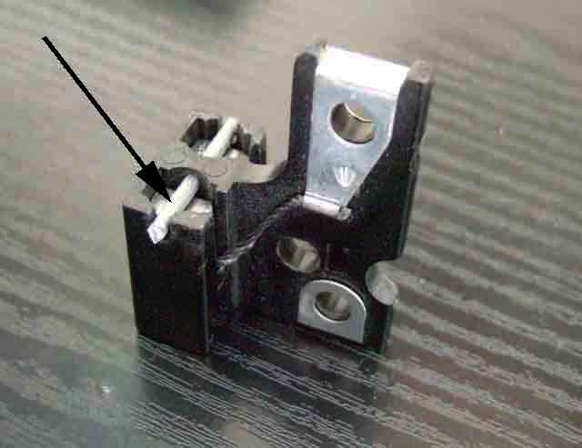
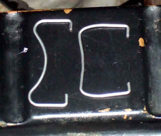
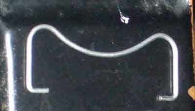 Simon Matthews asked about alternator connections on the MGs mailing list, and I responded. He wrote back directly to thank me and say he had sorted it out, and happened to mention that he had replaced the missing retaining clip as well. I suddenly realised that neither of mine have this clip, nor has a spare I took off a Metro years ago, but I do remember them from earlier cars. Did a bit of digging, and find it is 13H 8163 for the Lucas 16/17/18 ACR on the roadster, but nothing found for the AC Delco on the V8. Nothing shown in any of the usual suppliers, or anything useful Googling that part number, but Googling various descriptions I did find one as part of a repair kit from JCR Supplies. Contacted them and they sell them separately, so ordered two. But looking at my alternators the clips are of two different types. Perhaps not surprising given that one is Lucas and the other AC Delco, but ironically the clips I've ordered look like they will fit the Delco, but not the Lucas! That isn't an ACR but a later 1980s model, and the wire clips for that need the ends pointing outwards, whereas the ACRs and the Delco have them pointing inwards.
 Whilst one of the clips fitted the Delco the plug top was further away than it obviously is in the ACR series, and the clip wouldn't fit over. But it also moved from side to side in the holes, i.e. the clip was wider than a Delco clip, so it was a relatively simple matter to move the bends to make the legs longer and closer together which allows the clip to fit over the plug top.
 But the roadster alt is completely different, the 'feet' point outwards instead of inwards, then the upper part of the plug body is wider than the aperture in the rear case so the legs have to be bent outwards and then upwards again to fit round that, before the top part of the clip can go over the top of the plug. Those extra bends, plus the plug top being further away from the casing like on the Delco, mean the wire isn't long enough to modify. So I sketch the likely shape of the clip, and take a photo of the back of the alt, and send them off the JCR Supplies to see if they can tell me what it is, or ideally have a clip. They get back by return so say the alt is an A127, have located the correct clips and added them to their eBay shop - excellent service! Incidentally web sources indicate the A127 has anything from 35 to 120 amps output, potentially (ho ho) significantly more than the 34 amps of the original 16ACR, although 70 amps and over have an output stud instead of output spades.
Pulleys August 2019
For the alternator the Parts Catalogue lists 12H2516 prior to the 77 model year and 13H9514 for 77 and later. Alternative part numbers for the former are given as AUE1238, BAU1461 and AEU1238 which various sources show as 2.5". No alternatives for the latter number but suppliers like Moss and Brown & Gammons do not differentiate between them. Some sites show 12G1054 at 2.75".
For the V8 the Parts Catalogue lists 37H8023, no Google hits for that, Brown & Gammons lists BHM7044 but NLA, no size found.
 I didn't know how the above sources measure the size i.e. whether it is the bottom of the groove, the OD, or something in between, but subsequently to originally writing this section spotted in one of my Lucas catalogues a drawing showing it was simply the OD. The roadster has what seems to be a non-standard A127 so the pulley is an unknown quantity, and that measures 2.406" OD and 2.41" on a wrapped belt. Someone else has said theirs (original Lucas as far as they know) measures 2.875" OD. The V8 (original AC/Delco as far as I know) measures 2.96" overall diameter and 2.595" on a wrapped belt so a big difference between measure diameter and running diameter. An old alt from a Metro which I have as a spare for the roadster has a pulley of 2.7" OD and a wrapped belt is the same. OD is not good measure as the flanges can be anywhere from flush with the belt (as on the Metro alt) to several mm above it (as on the V8) and not have any effect on rotational speed.
The pulley size determines how fast the rotor spins for a given engine speed, and as there is a maximum rotational speed for both dynamos and alternators the pulley size is chosen to suit the maximum engine rpm. I can't see a speed given for the dynamo but the WSM specifies 12500rpm for both the 16AC and the 16ACR and 15,000rpm for the 18ACR. The crank pulley size also has a direct effect on dynamo/alternator rpm at a given engine rpm. An alternator is said to spin safely up to 18,000 rpm and a 2:1 ratio of alternator speed to engine speed is often quoted, which would be safe up to 9000 engine rpm (6250 or 7500 in the case of MGB alts). The maximum for a dynamo is typically 1/2 to 1/3rd of the alternator due to its construction. A dynamo rotor has heavy output windings as well as the commutator carrying output current, with the segments constantly connecting and disconnecting that current. The alternator has a much stronger rotor carrying lighter, lower current field windings, and slip-rings carrying that current as a constant flow. For that reason the pulleys for a given engine will be larger for a dynamo (to give a lower dynamo rpm) than the alternator, i.e. 3" as opposed to 2.5" or 2.75" for an alternator. Dynamo and early alternator engines used the same pulley. The oddity is that the V8, with a slightly lower revving engine, has a larger (as measured) pulley, despite having a significantly greater electrical load from its twin cooling fans and HRW, when 1977 and later 4-cylinder cars that had a single cooling fan got the smaller (higher output) 2.5" pulley in place of the 2.75". But then the V8 has a 6" pulley compared to the 5" of the roadster. I.e. 20% bigger, which would imply a 20% bigger alt pulley for the same maximum alt rpm, which would be 3". 2.96" as measured would be logical for the slightly lower maximum rpm of the engine, but the fly in that ointment is that the V8 belt sits well down in the Vee of the pulley and gives an effective diameter of 2.56", so the V8 alt at maximum revs is spinning some 20% faster than even the smaller 2.5" roadster pulley. The old Metro alternator with its 2.7" OD pulley gives noticeably less output than the 2.44" (measured, 2.2" effective) A127 on the roadster.
Converting Dynamo to Alternator
Probably the main reason for converting is to get a higher charging current as the dynamo is limited to 22 amps. Although this is usually adequate for most normal, and particularly 'classic' use, when stuck in traffic with headlights, heater fan etc. on the charge will almost certainly not be adequate which means you will be discharging the battery and on a daily driver this can rapidly reduce the battery to a point where it will no longer start the car. Bad connections will limit current flow, and will contribute to a drop in system and charging voltage, and I think it is this which people are seeing as much as insufficient output from the alternator. Even 'normal' volt-drops up from the solenoid and particularly with a voltmeter on the green circuit can be enough to reduce the indicated voltage below 12.5v, even though the voltage at the solenoid and hence the battery is above this critical point. A good example of a little knowledge being dangerous. Of course if you are going to significantly increase the electrical load then you may well need to consider an even higher rated alternator from another source.
One common misconception seems to be that fitting a higher rated alternator is automatically going to push more current through the wiring, and people get paranoid about uprating it. The maximum current that will flow depends (to the largest extent) on the electrical load, not the maximum capacity of the alternator fitted. If you only have 40 amps of load then only 40 amps of current will flow, even with a 60 amp, 80 amp or 100 amp alternator fitted. Having said that high-rated alternators like the 80 and 100 amp will be better at maintaining sufficient charge at idle if you have added electrical loads, as well as when running.
About the first thing to say about the process of converting from dynamo to alternator is that unless it has already been done you almost certainly will have to convert from positive earth to negative earth. Positive earth alternators will probably be very difficult if not impossible to find, a negative earth will be tricky to convert to positive, and the availability of used, rebuilt and new negative earth alternators of various types is almost infinite. Also it might be safer to take things one step at a time and do the polarity conversion first, check everything works OK, and only then do the alternator conversion. Getting the polarity wrong with an alternator connected will probably destroy it, and there is only one very simple step which will be 'wasted'. These notes only cover use of a Lucas alternator, there are too many variations in Bosch and GM Delco alternator connections, although the alternators themselves are quite suitable for use.
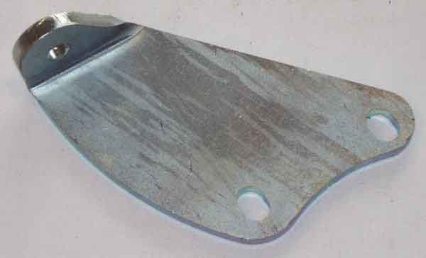 March 2013: As well as a suitable alternator you will also need an extended bracket to connect the rear mounting point of the shorter alternator to the original mounting points on the block. Unless this is done rigidly vibration can fracture the front mounting ear on the water pump, so extending the existing bracket in some way is not a good idea. Fortunately a number of places sell a suitable bracket - 12G1053, such as Motaclan/Leacy, Brown & Gammons, and Sussex Classic Car.
The usual advice is before starting any of the following work disconnect the battery earth strap first, and only replace it as the final step. However on cars with the remote solenoid it is very easy to remove the brown wire from the spade on the battery cable terminal on the solenoid, and as long as this can't drift back towards its spade while you are doing the work then this is fine.
Rewritten November 2012 (following the opportunity to work on Chris Mottram's car):
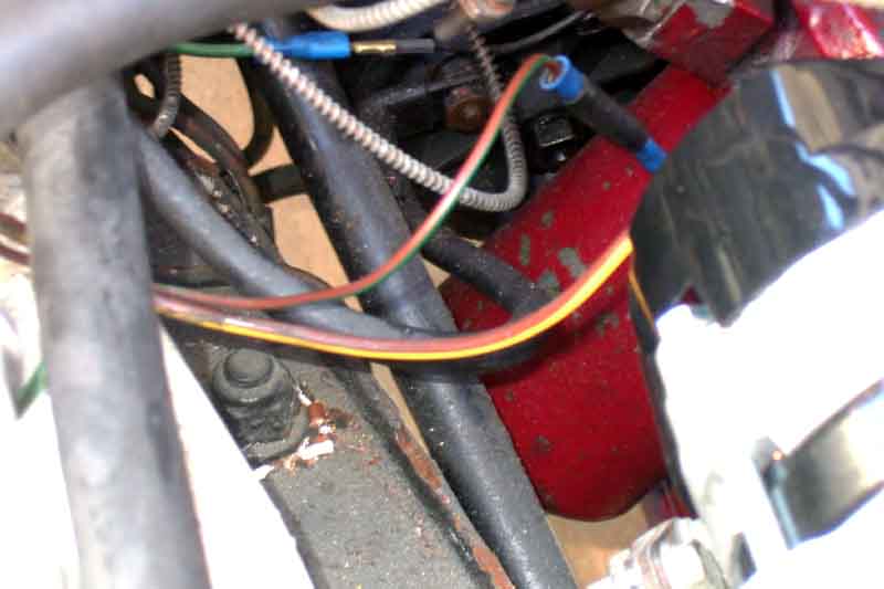 The dynamo circuit originally had a standard gauge brown/green (field) wire, and a thicker gauge brown/yellow (output) wire. Because of this it's best to use the thicker brown/yellow wire for the output of the alternator, even though this goes against the convention on cars equipped with an alternator from the factory. Therefore the brown/green is used for the INDicator wire, this is method 1.
There is an alternative method if you are adding a lot of significant loads to the cars electrics, and consequently fitting a high-power alternator, and that is method 2.
Method 1:
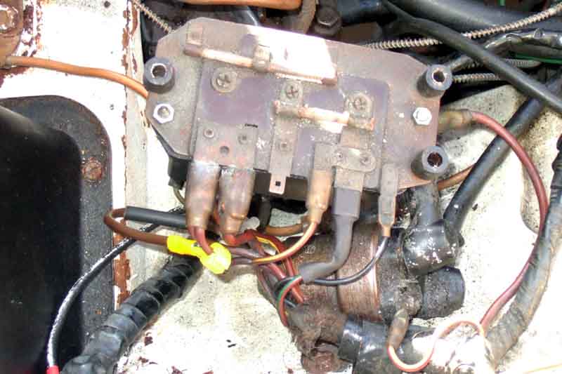 You can leave the control box in-situ and hence use it's spades for interconnecting most of the wires. But you must cut off the small spade from the brown/green and fit a large spade so it can be moved from the F terminal to the D terminal in place of the thick brown/yellow. The displaced brown/yellow then has to have its large spade cut off and be connected in some way to the brown circuit. The method used with a conversion kit from a well-known supplier is a ScotchLok connector, but these have a habit of working loose over time and are not a good idea on things like the alternator output cable which will carry quite a high current, and the slightest resistance will cause significant heat to develop as well as reduce the output of your shiny new alternator. You could instead use a ring terminal of the appropriate size and add it to the solenoid terminal that carries the battery cable. That would give a good connection, but you MUST disconnect the battery earth cable before working on this terminal. However in both cases you would need to extend the brown/yellow, which has its own problems as to what method to use. I suggest it's better to bite the bullet and remove the control box altogether, make proper soldered joints, and give better access to other components into the bargain.
Remove all the wires from the control box, and the control box from the panel on the inner wing (easier said than done with those fiddly nuts behind the panel!). The standard gauge brown/yellow from the WL terminal, and the standard gauge brown/green from the F terminal have their spades cut off, a portion of insulation carefully stripped so no strands are cut, twisted together, and soldered. Put a couple of lengths of heat-shrink tubing just over the soldered section, each about 1/4" longer than the soldered joint, heat-shrinking them one at a time. Then fold the 'spare' bit of tubing over, and fit a couple of lengths of larger diameter tubing over that and an inch or so of the insulation on the wires. This circuit supplies the 'priming' voltage to the alternator to start it charging, and indicate charge failure.
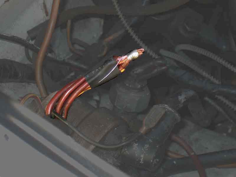 The three original browns from the B terminals on the control box, and the thick brown/yellow that came from the D terminal, are dealt with in much the same way. Cut all the spades off, making the four wires the same length, and strip about half an inch of insulation from each, being careful not to cut through any strands. Check the conductors are clean, using fine emery if tarnished. Twisting four, heavy gauge wires together is not really advisable, so I used the method adopted by the harness manufacture for the sealed, multi-way junctions that exist on some of the MGB harnesses. First I put a short piece of heat-shrink over the insulation of all four wires to keep them together. Then I got a strand of tinned copper wire and wrapped it round the four conductors, for the length of the stripped section, to make a good mechanical joint, only then did I solder the joint. As before a couple of lengths of heat-shrink about a 1/4" longer than the soldered joint are fitted over the soldered part, then the 'spare' bit at the end is folded over, and a couple of pieces of larger diameter heat-shrink fitted over that and an inch or so of insulation, as with the previous two wires.
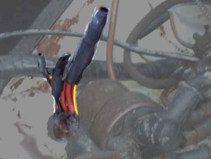 Finally that leaves the earth wire from the control-box. It's best not to leave this floating around, but rather than cut the spade off I folded it over and again used heat-shrink to insulate it. That leaves three heat-shrunk spurs sticking out of the main harness at various angles, but a cable-tie can be used to attach those out of the way against the panel the control-box came from.
Method 2 is very similar but to carry higher currents, if you are adding significantly to the cars electrical load and hence using a high-output alternator, it would be best to use a new heavy gauge (of the appropriate size for your loads) brown wire from the output of the alternator to the battery cable stud on the solenoid at least. You may also need to use similar gauge wire from there to your non-standard, high power loads, the brown from the spade on the solenoid going to the control-box should be enough for all the factory loads. Again, you MUST remove the battery earth connection before starting work on the battery cable stud on the solenoid. After that you can leave the browns on the control-box B terminals, and the brown/yellows on the WL and D terminals, using the heavy gauge brown/yellow at the alternator for its INDicator terminal. The standard gauge brown/green should be removed from the control-box F terminal and its spades taped back and insulated at both ends to prevent them coming into contact with anything else. Alternatively you can discard the control box and join the three browns from the B terminals, and join the two brown/yellows, and insulate the earth wire, using the techniques described above.
If converting the polarity at the same time leave the alternator unplugged when connecting the batteries the new way round for the first time, if you get it wrong and the alternator is connected you will blow its diodes and burn wiring. Confirm the polarity is correct before continuing by connecting a voltmeter between a brown in the alternator plug (meter +ve) and an engine earth (meter -ve).
After confirming that the polarity is correct connect an analogue voltmeter (digital meters may give unpredictable results) on its 12v scale in place of the battery earth strap. There should no voltage registered. If there is, it will probably be a full 12v, and means some circuit on the car is switched on (courtesy lights? Boot light?) which should be found and switched off before proceeding. When no voltage is shown plug in the alternator. You may now see a few volts registered, which will be the normal microscopic leakage current of the diodes and can be ignored. If a full 12v is shown the alternator diodes are faulty. If the reading is correct, replace the battery earth strap. If you don't have an analogue meter use a low-wattage 12v bulb instead, such as one from one of the gauges. If there is any glow at all from the bulb, current is flowing, proceed as above. Only a significant current flow will cause the bulb to glow, connecting the alternator should not be enough.
You now have the alternative of going for broke and reconnecting the battery earth strap, or taking a smaller step. For this connect a high wattage bulb e.g. a headlamp bulb (e.g. an old one with one filament gone - "If you haven't found a use for something yet ...") in place of the earth strap. This will allow a safe amount of current to flow while you turn each thing on in turn. If any circuit is faulty and is full short the bulb will limit the current and prevent damage to wiring and components. Some things (low current items) will work almost normally, higher current items probably not. Low current items might cause a dim glow from the bulb, higher current items a brighter glow. Only turning the key to crank (nothing will happen) should cause the bulb to glow at full brightness, nothing else. When you are happy, reconnect the battery earth strap.
With the ignition off there should be no glow from the ignition warning light. A glow now indicates faulty alternator diodes or voltage regulator, or incorrect connections to it.
With the ignition on the warning light should glow. If no glow remove the plug from the alternator and connect an earth to the brown/yellow terminal (NOT the brown!). If the warning light glows now the alternator is faulty if not then the circuit is broken back towards the warning light, possibly where the brown/yellows are joined where the control box was, or a blown bulb. There should be 12v on the white at the bulb holder and an earth on the brown/yellow to light the bulb.
With the warning light glowing start the car, and with the engine revved above 1000 rpm the light should go out. If the light remains on the alternator is faulty. Only if the revs drop below about 600rpm should the light come back on, stay off till about 1000 rpm, then go out again as before. Early cars had an idle speed of 500 rpm and if the light comes on at idle, particularly with lots of load switched on, then you would be advised to increase the idle speed to, say, 700 rpm to keep the light out at all times. While the light is on the alternator isn't charging and the battery is discharging, which largely negates the effort of converting!
With the engine at about 1000 rpm, and all loads switched off (and the warning light off), measure the voltage between the brown at the fusebox and earth. You should see about 14.5v, much less or more than this indicates a faulty alternator. Now turn on headlights, brake lights, heater fan etc. The voltage will probably drop, possibly to less than 13v with one of the smaller Lucas alternators. Increase the revs to about 3500 and the voltage should rise above 13v again, indicating the battery is still being charged even with everything switched on. If the voltage doesn't rise above 12.5v check the voltage at the alternator output terminal(s), and if similarly low here it indicates the alternator has a low output current fault, however note that the smaller Lucas alternators will probably not be able to supply anything above the standard factory loads at best. If the voltage is closer to 14v at the alternator then there is a bad connection somewhere between the alternator and the brown at the fusebox, check the voltage on each brown wire and the battery cable at the solenoid.
Converting 16AC Alternator with Separate Regulator to Later Alternator with Integral Regulator Added October 2007
First remove the battery earth strap, and don't replace it until you have made all the wiring changes.
The alternator should have the following wires:
Black (earth/ground)
Brown/yellow (Indicator) coming from the voltage regulator
Brown/green (field) coming from the voltage regulator
The voltage regulator should have the following wires:
Brown (12v supply to the voltage regulator) coming from the solenoid
Brown/green (field) going to the alternator
Brown/yellow (Indicator) going the alternator
Brown/black (Indicator) coming from the ignition warning light
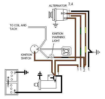 These last two (brown/yellow and brown/black) are probably the most important. They are electrically connected together at the voltage regulator, and they must remain connected together and isolated from everything else after the conversion, so that effectively the Ind terminal on the new alternator is connected to the warning light. As well as lighting the warning light, the current flowing through the warning light to the alternator acts as a 'pump primer' and is needed to get the alternator to start charging. If both wires are in the same spade connector then all you have to do is securely insulate that connector so it cannot come into contact with anything else. If they have two separate spade connectors then these should be cut off, the wires twisted and soldered together, and the joint insulated with at least two layers of heat-shrink tubing (slip these on before twisting and soldering!).
Of the other wires the heavy gauge brown goes to the output terminal of the new alternator (See here for Lucas 16/17/18ACR terminals) and remains on the solenoid.
The two black wires and two brown/green wires at the alternator and old voltage regulator are no longer required and should be taped back out of the way of anything else.
Note that the earthing point to the body for the black wires from the regulator and alternator is also the earthing point for four other wires (heater fan, instruments, wipers and headlights), even if the regulator and alternator earth wires are removed the other four wires must still be earthed, you will get some very strange results without it.
That should leave the brown going from the voltage regulator to the solenoid, and this is also no longer required. If the two standard gauge wires at the solenoid (there should only be two apart from the large battery cable and the heavy gauge brown from the alternator) have separate spade connectors it should be easy to determine with an ohmmeter which goes to the voltage regulator and which to the fusebox. The one going to the fusebox must remain connected, but the one going to the old voltage regulator can be taped back both ends. But if these two brown wires terminate in the same spade connector then you have a 50/50 chance of cutting the right wire off. You could cut one wire off and then test, and if you have cut the wrong wire reterminate it on a new spade connector and tape the other one back, or cut both off and test and then reterminate the wire going to the fusebox, taping the other one back. But the best thing to do would be to cut both wires from the existing spade connector, identify the one going to the old voltage regulator and tape that back both ends, then for the other wire that goes to the fusebox reterminate that on a ring connector that will go on the stud with the battery cable. This makes a more secure connection than the spades, as all the current for the cars electrics goes through it. While you are doing that you can do the same with the output cable from the alternator, for the same reason. Later starters did have all the browns terminated with ring connectors on the battery cable stud as standard.
With all the wiring changes done, the new alternator mounted but the brown and brown/yellow not yet connected (make sure they can't short out on anything), and everything in the car switched off including doors etc. closed so the courtesy lights aren't on, check to make sure you haven't shorted any of the brown wires to earth/ground. The safest way to do this is to connect a voltmeter on its 12v scale in place of the battery earth strap. If the voltmeter shows any reading at all, there is something drawing current. Anything less that 12v shown is a tiny current, could be a clock or the 'keep alive' circuit of a radio. If it shows a full 12v it could be a small current e.g. something simple like a courtesy light left on, or it could be a full short. Connect a test-lamp or other 12v bulb (an old headlamp bulb is best) in place of the earth strap, and if it glows brightly it is a full short which must be investigated and fixed before you proceed.
A cruder check is to tap the battery earth strap very briefly on the -ve post of the battery. You should not get any kind of a spark. If you get a small spark maybe one of the courtesy lights or similar is still on. If you get a big flash then it looks like one of the browns is shorting to earth somewhere, which again must be investigated and fixed before you proceed.
With the brown at the alternator still not connected and protected from shorting to anything, and with the battery earth strap reconnected, connect the brown/yellow to one of the standard sized spades and turn on the ignition. If the warning light glows you can proceed. If it doesn't then turn off the ignition, move the brown/yellow to the other standard sized spade and try again. If the warning light glows now again you can proceed. If not, disconnect the brown/yellow from the alternator and connect an earth to instead end and try again. If the light glows now then possibly the alternator is faulty, or possibly the wire should go to yet another spade if you have non-Lucas alternator. If the light doesn't glow with the earth connected however, then either there is a problem where the brown/yellow joins the brown/black, or the bulb has failed, or there is some other open-circuit between the end of the wire at the alternator and where the white from the bulb joins the others at the ignition switch. This must be found and fixed before you proceed, or the new alternator probably won't charge.
With the bulb glowing with the ignition on, carefully connect the heavy gauge brown to the output spade, remembering it is live and unfused. You may prefer to disconnect the battery earth strap again while you attach the brown output wire, then go through the same tests for a short as before. With other types of alternator there can be different connection arrangements, some have an output stud as well as an output spade, use the stud as it will have a better current carrying capacity.
With both output and indicator wires connected to the alternator, start the engine revving it as little as possible, and watch the warning light. The warning light may still be glowing, so slowly raise the revs, and at about 900 rpm the light should go out. Now use a volt-meter on the brown at the fusebox and you should see around 14v. If so the new alternator is charging. With the engine idling turn on the lights, press the brake pedal, switch on any other electrical loads you can, and the voltage will drop to some extent, possibly towards 12v. Rev the engine to about 3k and the voltage should rise again above 12.5v. With everything turned off, and a fully charged battery, and the engine revved to about 3k, you should see a maximum of about 14.5v. With the engine idling again select 4th gear, handbrake and footbrake on, and slowly lift the clutch pedal up so the revs start to drop. The warning light should come on again at about 600 rpm. Dip the clutch again and take it out of gear, slowly raise the revs again and the light should go out again at about 900 rpm. If your normal idle causes the warning light to come on again anyway, it might be an idea to raise the revs a bit so it stays out, that way the alternator will still be charging at idle, rather than the electrical loads of the car draining the battery.
If the light doesn't go out when revved, and you have two standard sized spades on the alternator, switch off, and move the brown/yellow to the other standard spade. Turn on the ignition and if the light glows start up and try the tests above again. If the warning light doesn't go out when the engine is revved, with the brown/yellow on any of the standard sized spades that it glows on with the ignition on, or the voltages don't show as above, then possibly the alternator is faulty.
'One-wire' Alternators Added January 2010