


Headlights
Switch Connections
'Lights on' Warning Buzzer
Number Plate Lights
Brake Lights
Indicators/Turn Signals
Instrument Lighting
Ignition Warning Light
Map/Interior Lights
Roadster boot/GT loadspace lights
Reversing Lights
Hazard Flashers
Side-marker Lights (North America)
Fog & Spot lights
Switch Illumination
Brake and Seat-belt Warning Lights
Fusing
Bulbs
Daytime Running Lights (DRLs)
1st January 2021: MOT rules have been changed to fail cars with LED headlamp conversions:
4.1. Headlamps
4.1.4. Compliance with requirements
"Existing halogen headlamp units should not be converted to be used with high intensity discharge (HID) or light emitting diode (LED) bulbs. If such a conversion has been done, you must fail the headlamp."
October 2020: The legality or otherwise of LED external lighting, from Classic Car LEDs and the Federation of British Vehicle Clubs.
Chrome bumper front and all and rear park/brake/indicator light clusters rely on the physical fixings to the wings to pick up an earth, as do number-plate lights that are mounted on the bumpers and overriders. Corrosion, particularly at the front where both front and rear of the panel are exposed to water and salt, can cause problems with these lights, rear clusters being inside the boot/load space are protected to a large extent. When there is a bad earth feeding a light unit with more than one bulb or filament such as chrome bumper front park/indicator light units and all rear light units you will get interactions between them when more than one is powered, i.e. some being dimmer than they should be and others glowing dimly when they shouldn't, known as 'discoing'. Rubber bumper front indicators have a wired earth, shared with the headlights, as do the front 'parking' lights which are part of the headlamp assembly, and these can also experience unwanted interactions if the fault is in the earth wiring or its connection to the body. Reversing lights and number-plate lights that are attached to the number-plate backing-plate also have a wired earth.
With any bulb you can get a bad connection between the bulb base and the bulb holder causing dimness, with dual-filament bulbs it can cause unwanted interactions between brake lights and parking lights as well, but the single filament bulb for indicators (usually) will be unaffected. If multiple circuits on both sides are affected particularly when the indicators are being used i.e. 'discoing' then the problem is more likely to be where the light unit is attached to the wing.
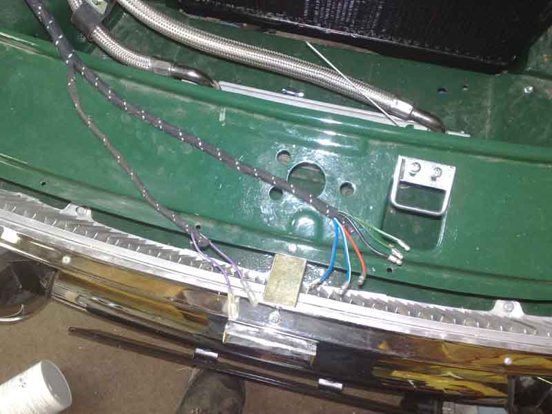 One oddity on early cars (for those used to later ones) is that the main harness only has one group of bullets at the front, not one by each headlight as on later cars. This reaches to the middle of the car i.e. behind the latch, and the tails from both headlights and parking/indicator lights also reach the middle of the car. At least, they did originally, but it seems some current stock has tails that only reach the later main harness bullets by the headlights. These tails are not itemised in the Parts Catalogue, suppliers have them as BAU2110 (for CB cars, BAU2111 for RB)
 Later harnesses have a group of bullets by each headlight, which should be relatively easy to access on cars other than V8s and 4-cylinder 1977 model year and later from between the radiator and the slam panel. On the others you have to remove the mesh grille, and access is still pretty restricted.
For 1977 until the end of production on all models the main lighting switch moved to the side of the steering column cowl - right-hand side on RHD cars and left-hand side on LHD. Care is needed on refitting the cowl as it is possible to trap the lighting wires, which being unfused will burn the harness.
Parking lights (aka sidelights or position lamps, not to be confused with North American 'side-marker' lights!)
1970 on
CB front units
RB front units
Rear units
 The parking lights were not fused originally. Mark II cars introduced fuses, although for 1968 and 1969 the fronts were on one fuse and the rears on another, so if you had a fuse fail you lost both at one end, a particular problem at the rear as you lose all lighting until you brake. The fuses were of the in-line type, installed where the rear harness joined the main harness near the fusebox. Fuses can be added to Mk1 cars quite easily to make them the same as 68/69 cars.
 For the 1970 model year a four-fuse fusebox was provided, the additional two fuses (at the top) separately fusing each side, with additional wires run to the front and the rear of the car. This was a much better arrangement which in the event of a short and a fuse blowing you still had one front, one rear, and the number plate light on one side still working. There is only one wire (red/green) feeding the front of the parking light fuses - they are linked there, which means if refitting these fuseboxes you must be careful to fit it the right way up, or you can get the brown and purple circuits linked to the green and white circuits, i.e. effectively powering the ignition all the time. If one side has failed check the cleanliness of the fuses, fuse holders and connections. Be aware that the fuse holder is riveted to the connection spades on the back of the fuse block and corrosion can also occur here.
From 1970 North America used a dual filament 21w/6w bulb for the front indicators and parking lights for both CB and RB models, with an all-amber lens. Prior to that it seems that the lens used with the two separate bulbs could be either mixed amber and white as per non-North American models, or all white.
 At the same time the location of the studs on the front indicator/side-light unit seem to have moved from being in-line in the centre of the light unit to being in opposite corners. Clausager says some export markets may have required the indicator part to be outboard of the parking lights instead of the other way round as in the UK which studs in line would allow, and may have been done inadvertently on other cars. But if you think about it with the studs in opposite corners the light unit can still be reversed! They would both need to above or below the centre-line to prevent that but still sit correctly on the plinth, so the reason for the change remains a mystery. The Leyland Parts Catalogue and suppliers such as Moss Europe and Brown & Gammons only list one light unit (BHA4966), and with suppliers showing both types of wing (with Moss showing the two different stud arrangements) it begs the question of how can the one light unit fit both wings? This question arose when Dave O'Neil wondered why, when he needed to replace one on his Mk1, neither of the NOS units he had in stock had studs in the right place for his wing, in fact one didn't have any studs at all! In the end he decided not to drill the wing (as someone suggested), but to drill holes in the correct places on the unit he had with no studs. He went to the extent of squaring them off, and used the studs from his old light unit, they pressed out and back in quite easily (as I found with a number-plate light unit). The wing aperture is also different but that doesn't seem to hinder fitting modified later units to the earlier wing.
This reminds me of an issue I had fitting new ones to the roadster - the chrome surround was pressed up against the paint when everything was screwed together, and I'd seen that had cut into the paint on a concourse example at the Classic Car Show. I ran a nut onto each stud first and that spaced it away, but left visible gap through as the sponge pads are not thick or dense enough. But a couple (from memory) of extra pads each side solved that.
North American spec cars got the same one-piece amber lens in the front bumper as RHD and other LHD cars, but the light-unit is different as it contains a dual filament 21W/6W bulb with offset location pins, the same as the stop/tail lights. This means that when the lights are on the indicators flash bright-dim-bright-dim instead of on-off-on-off. The Leyland diagrams are confusing as they still show the same two-bulb light unit as for chrome bumper cars, instead of a single bulb with two filaments as are shown for the stop/tail lamps. As the Advance Autowire diagrams show all lighting filaments separately there is no indication as to which is shared with which, for light units or bulbs.
Having upgraded the headlights to HID it left the halogen pilot lights looking distinctly yellow, and the same would be true for LED. I could use LED pilots - mine are wedge 501 T10 - but I have also pondered using them as DRLs if I can get some bright enough. Halogen are 1.7W but LED are classified in lumens (as well as colour) and can range from 300lM single element to 900lM multi element. Check the physical sizes as while many are the same as halogen at 25mm the brightest can be 34mm or more. I settled for 500lM which were the brightest I could find in the standard size, being in the headlight length probably wouldn't be an issue but I didn't want to risk it. I did find some 900lM at 34mm but the postage on those was more than the bulbs. The 500lM have an element on the front as well as a series of them round the side which I hoped would shine in the reflector, but unfortunately they don't.
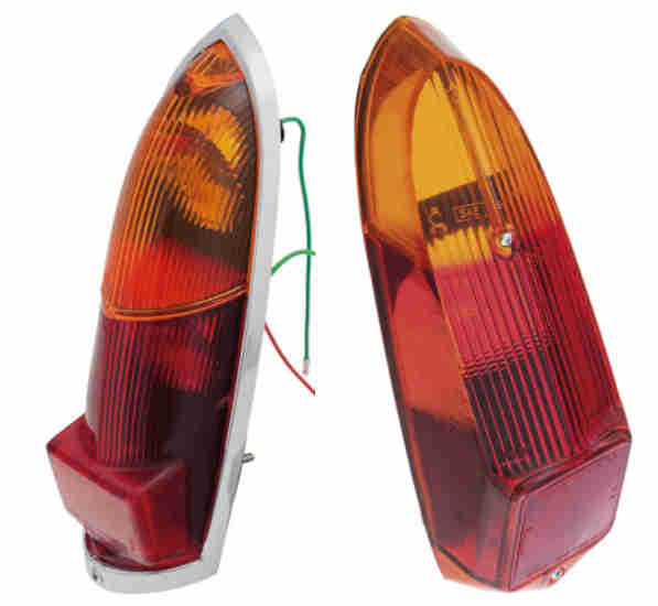 The only significant change in the rear light clusters was for the 1970 model year when the lenses changed from rounded to angular.
 Special 'nuts' (BHA 4242 'Dotloc', NLA, use 10/32" UNF with star-washer) were used to attach the rear light clusters to the wings. These have a spike that scratches through the paint to get a connection - pretty crude but there we are, and being in the boot/load space it's better protected from wet and salt weather than other light units. I've also heard of a problem causing interactions between dual filament stop and parking light circuits where the connection between the bulb-holder and bulb was good, but the bulb holder was making a poor connection to the base of the light-unit. You can test for this from the back i.e. inside the boot or luggage space. March 2020: This has just cropped up again on the MGOC forum where the owner noticed the parking lights had started coming on every time he applied the brakes, but there were no interactions involving the indicators. Cleaning everything in sight seems to have fixed it, but no root cause tested for or identified. Incidentally he first noticed this when all-LED lighting was installed, still there when standard bulbs were installed. Now the standard bulbs work as they should, but LED stop/tails cause the original problem again.
 |
LED park/stop/tail lights |
|
Trim Ring Headlamp Adjustment Headlamp Mounting Uprating
As far as I can tell up to the 77 model year MGB headlamps were sealed beam. In the UK prior to 1970 GLU101 60/45W, then it gets a bit confused. The Parts Catalogue says for GLU101 'use before BHA4999' but that number isn't listed in the catalogue index nor does Google show anything for it. The next entry for 1970 to the end of chrome bumpers for 4-cylinder and V8 says GLU106, which the V8 Driver's Handbook (only CB cars) says is 75/55W, but the late CB 4-cylinder Driver's Handbook says 'GLU101 75/55W'. For rubber bumpers GLU123 is listed, and again I can only find two references both saying it is a sealed beam 75/50W with pilot light. For 1977 on H4 GLB472 halogen bulbs were used which any number of sites say is 60/55W. There were many variations for other markets and years.
 The headlamp always used a 3-pin connector. On sealed beam rubber bumper cars it was combined with a holder and shroud for the pilot light to hold the pilot light against a 'window' on the sealed beam unit. From 77 on the halogen connector supports a gaiter that carries a separate bulb holder and positions the pilot bulb in a hole in the reflector assembly.
Headlights were never fused from the factory and if uprating them with higher power halogen and particularly with relays consideration should be given to fusing them.
Headlights have a wired earth, to a bolt near the right-hand headlight on early cars, moved to near the fusebox on later cars, probably with the alternator in 1968, but definitely with the starter relay in 1970.
On these later cars the main harness has several bullets and a tail by the right hand headlight for lighting and horn that side. The three headlamp wires are duplicated as one set brings power in to that point, and the second set feeds power back in to the main harness which then goes across to the left-hand side. Additionally there are single wires each side for the parking and indicator lights, and a 2-wire (until 1977, then a single wire) tail each side for the horns. One disadvantage of this arrangement is that the main and dipped beams for the left-hand side have to go via double bullets by the right-hand headlight as well as single bullets by the left-hand headlight, giving more opportunities for poor connections than the earlier arrangement, and these bullets suffer most from corrosion due to their exposure to the elements.
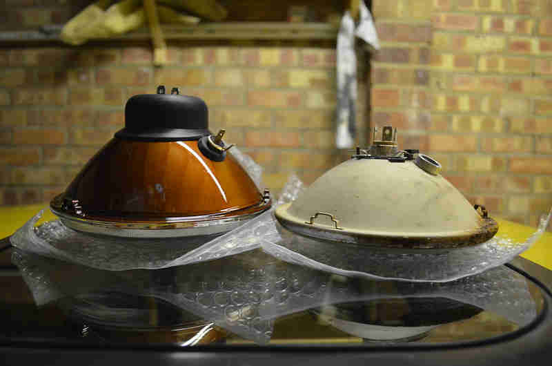 You have to be careful with replacement headlamp units as some are too deep to fit in the bowls.
 Brighter halogen bulbs are a direct replacement in these 77 and later cars, but to fit them to earlier cars you also need an H4 conversion. Many variations of these, some are described as having 'flat' glass, Vee has H4 with a domed glass (presumably a PO mod), although the dome is only half the height of that on Bee's sealed beams. They both have various ribs and patterns moulded into the glass so you have to see them side by side or measure the protrusion of the lens to see the difference, and some of them are too deep to fit in the bowls. The truly flat moulded glass variants are a little more obvious. But there are also variants with plain flat glass where all the focusing and beam shaping is done in the reflector rather than having a plain reflector with the moulded glass as originally, and these look very different. There are also LED conversions originally produced for Land Rovers which make the headlight black to a greater or lesser degree and these look truly horrible on an MGB.
There have been comments about how poor sealed-beam headlights are and at one point they were uprated slightly for the UK market. When converted to H4 halogen the wattage reverted to the earlier value, however it's quite likely that the perceived brightness did increase which can be done through manufacturing techniques while keeping the nominal wattage i.e. current drawn the same (see Uprated Halogen). However the difference between sealed beam and H4 on the MGB is negligible compared to the difference between H4 and HID on modern cars.
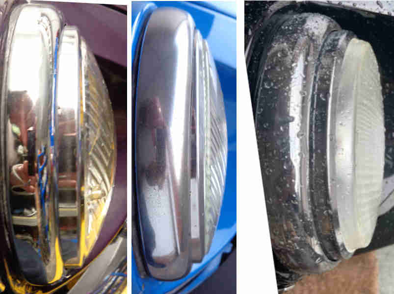
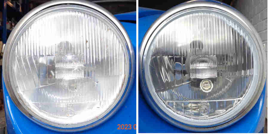 Needing to replace one of Vee's headlamps (with the same type - Moss quad-optic) I was surprised how 'misty' the reflectors/back of the lens had become with the new one fitted, so had to replace the other one.
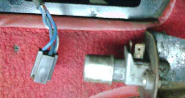 There was a floor-mounted dip-switch until the 1970 model year, column-mounted after that.
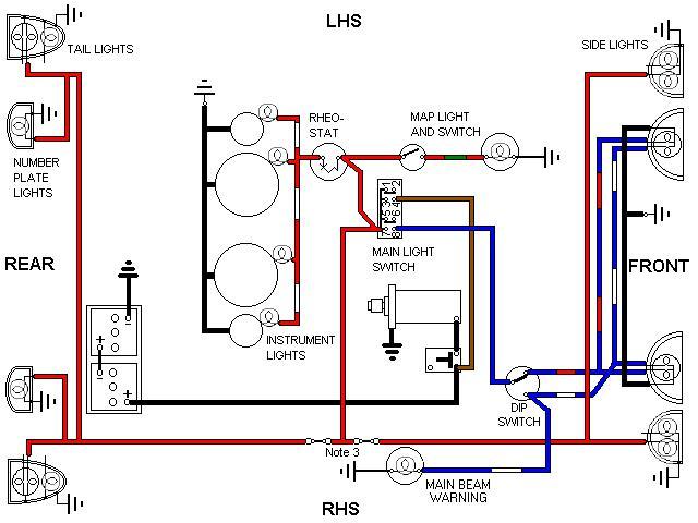
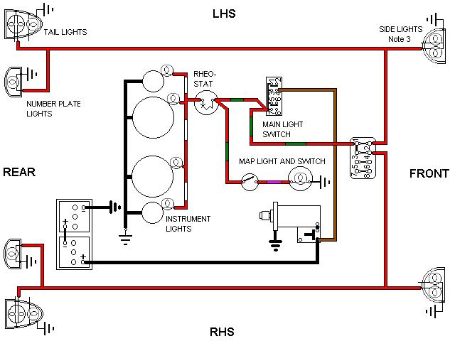
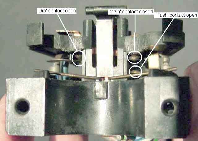 The column mounted dip-switch can be a bit difficult to puzzle out as it incorporates a headlamp flasher, indicator/turn signal, and on some years the horn wiring as well. The accompanying pictures show which contacts are which as far as the dip/main/flash circuits go. Several problems can develop with this unit, like failure to flash or light the appropriate lights, failure to cancel, loss of spring tension, etc. There is some scope for repair, although like many components of that and later eras they were only intended for one-off assembly and use, replacement thereafter, which isn't cheap.
As far as the wires go:
The dip-switch should have three fore and aft (towards you and away) positions: Clicked towards you lights the dipped beams. Clicked away from you lights the main beams. Both of these are only when the main lighting switch is in its 'headlights on' position. In the dipped beam position the lever can also be pulled towards you against spring pressure to light the main beams in 'flash' mode, and this is independently of whether the main lighting switch is on or off. When released the lever should return to the central/dipped beam position to extinguish the main beams. If the lever is pulled towards you when the headlights are on, the main beams will be illuminated from the headlamp flasher circuit as well as the dipped beams from the main lighting circuit.
Some of the contacts are fixed and others are 'springy'. The springiness applies pressure to the contacts to give a good electrical contact, but all the contacts can burn and blacken over time which can reduce headlight brightness and cause the switch to get warm in use. Cleaning of all the contacts and careful bending of the spring contacts can restore functionality, but it is easy to overdo it and mess things up even further. The contact springs are nothing to do with limiting the fore and aft movement of the stalk or the spring return from the flash position, they are derived from plastic 'springs' on the switch body and arm, as indicated in the accompanying pictures.
 Fitted in the speedometer on Chrome bumper cars except V8, in the panel by the speedometer on V8s and RB cars. In the former case it uses a 'claw' type single-wire instrument bulb holder 13H1924 picking up an earth from the metal case of whatever it is pushed into. In the latter case it uses a 2-wire bulb holder and a wired earth (BCA4780) as it is fitted to a plastic panel. I suggest the original reason for fitting them was with the push-push dip switch as that gives no feedback as to which way it is switched. Our column stalks will tell you at a touch, but modern pull-pull stalks take us back to 'no feedback' and are an abomination, I have to look at the tell-tale on my ZS 180 to see if they are on or not when first turning on headlights. It would be better if they didn't 'latch' to main-beam while not turned on. Should I use an LED in this position? It's up to you, but I wouldn't want the additional brightness of an LED when I'm driving on unlit roads at night. Also with column stalks as said above you can tell at a touch if you are on main beam, and I suggest you would need to be driving a very long time after switching them to main beam to forget to dip when you see approaching traffic.
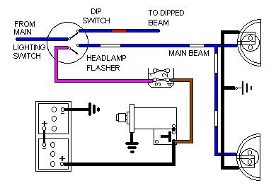
For 1970-on the headlamp flasher switch was part of the dip switch, see here for wiring and operation.
If your lights fail while you are driving at night,
and if you have the presence of mind when suddenly plunged into blackness at 60mph on a mountain road,
try the other beam (dip to main or vice-versa) or pull on the headlamp flasher. Because the headlamp flasher gets its supply from a different source it bypasses any problems in the main lighting switch or dip switch. It may just be enough to enable you to bring the car to a safe halt.
If you have done any work involving removal and refitting of the front wing or any headlamp components, I would strongly recommend you leave the rings off until successfully passing the headlamp alignment test in the MOT or remove them yourself beforehand, likewise if taking it somewhere for headlamp alignment for other reasons. You don't want some scruffy oik in a garage levering them off.
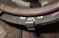
The theory is that the top is retained by two lips on the headlamp bowl, and the bottom by a spring-clip attached to the bottom of the bowl that rests in the curve of the trim ring when fitted. The clip is supposed to slide out of the curve as the bottom of the ring is eased forwards, however open to all the weather the clips and the trim ring can rust and make this extremely difficult. Going by the Parts Catalogues all MGBs had the same trim ring regardless of year - 57H 5296, although late models seem to have had rings with notches in to allow for adjustment without removal.
Some years ago I replaced one of the bowls on Vee as it had rotted, and the replacement from the MGOC came with a screw fitting instead of the spring-clip. This is standard for cars using the same headlight like the Mini, which has a screw-hole in the bottom of the ring (one of the Parts Catalogue drawings does show such a screw, but this must be an error as the part number is the same as the others), however there is no access to such a screw on the MGB. Fortunately the spring-clip on the old bowl was reusable and I could change them over. Subsequently I worked on a car with aftermarket Wipac plastic headlamp bowls that also had the screw, but no option to replace that with a clip as it was a one-piece moulding. But the screw had been fitted to the bowl before the ring, and adjusted such that the head just fitted into the curve of the ring. Careful adjustment is needed to get the screw just right so the ring doesn't fall off (screw in too far) or jam (screw not in far enough), but get it right and it is easier to get the ring off and on than the original spring-clip.
But back to the original arrangement. There seems little option but to lever the bottom of the ring forwards somehow until hopefully it pops off the spring-clip at the bottom ... but that has never happened for me. Brute force has been needed to pull the bottom of the ring off the clip which bends the clip forwards and it has to be pushed back again to refit the ring, with the risk of eventual fracture. Pressing down hard on the top of the ring with the other hand can help, until you can see what is going on inside. Tackling Vee's which hadn't been moved for about 10 years or so I could see that instead of a recess in the spring sitting on the rear edge of the trim ring, the end of the spring had lodged behind a lip on the rear edge of the ring. This means that instead of the ring sliding off the clip as the ring is eased forwards, the clip has to be bent right forwards, severely distorting it. With the bottom pulled forwards this far I did then try levering the ring upwards to get the top of the ring unhooked from the two lips at the top. I could get the one side off but not the other, so had to resort to putting a small screwdriver through the gap at the bottom and levering the clip up off the ring, but as often as not the screwdriver slips off. I put fresh Waxoyl on the back of the ring and on the clip and tried refitting it with the recess of the clip sitting on the rear edge of the ring, but as soon as I pushed it home the end of the clip dropped down in front of the rear edge of the ring just as before, and trying to remove it again even with fresh Waxoyl I was back to square one. I then tried pushing the spring as far back and upward as it would go, and this time the recess in the clip did stay on the rim of the ring. This did make it easier to remove, although still required some force, and pulled the spring downwards and forwards again, so had to be pushed back and up again before refitting. If there were a small cut-out in the rear edge of the ring such that you could rotate the ring to line that up with the clip it would make life easier, and indeed some of the rings in the Parts Catalogues do show a cut-out in that location, but again the part numbers are the same as before. It's possible that the design was changed at some time, but kept the part number as the change was so small and it was fully backwards compatible. But replacement rings bought in 1990 for Bee do not have the cut-out. However you get the ring off, daub the back of the ring with Waxoyl to protect that from rusting through from the back as well as to aid fitting and removal, and daub the spring-clip as well.
Combined trim-ring puller and beer-bottle opener! December 2020
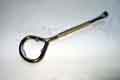 Many years ago and occasionally since I have heard Americans talking about using a 'paint can lid remover' to get these rings off. But since I've been using screwdrivers to open paint cans for the past 55 years I couldn't imagine what they were like and how they were any better, and there were no images and precious little internet in those days. More recently a pal in Philadelphia happened to mention it, and asking him about it he made a video to show what it was like and how he used it, and because I was interested he very kindly sent me four. Initially I had Googled 'paint can lid remover' and although there were a few of a similar design in the UK for a couple of pounds the end of those was basically flat and not much different to a screwdriver, whereas the American ones are almost a right-angle at the end. Then I found them on Amazon UK, but they are supplied from the US at Ł10 including P&P which is quite pricey. The bonus feature of this ring-handled type is that they can also be used to open beer bottles!
 I start off at the side but because the end is bent at a right-angle the ring can be pulled forwards rather than levering against the wing. As the lower half of the ring comes forwards, the tool is moved down and round to pull the ring further forwards at the bottom.
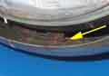 With the ring pulled forwards 1/2" or so the clip is visible, but trying to lever it up off the ring with a screwdriver doesn't work as it just slips off nine times out of ten. Brute-force has to be used which bends the clip right forwards, and it has to be pushed back again to refit the ring. How long it would stand up to that treatment without fracturing I don't know.
 The difference with this tool is that with the end angled upwards under the clip it can be levered up from the ring very easily, the clip is not bent, and the ring just snaps back into place when refitting. To check it wasn't a fluke I tried it on the other side of Vee a couple of times with the same result. I haven't tried Bee yet as I'm not expecting to have to remove the rings any time soon, but on Vee with the new uprated headlights they may need adjustment at the next MOT. Nevertheless I shall keep one in each car - just in case.
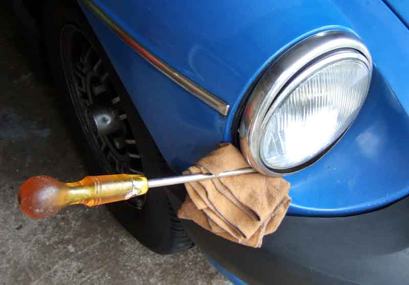 Without a tool such as the above there seems little option but to lever near the bottom of the ring with a screwdriver using the curve of the wing as a fulcrum, and a thick pad to protect the paint. Note that sound wings are required to perform this manoeuvre! Then use brute-force to pull it off the clip. It's the only method that worked for me for 30 years, fortunately not a frequent operation.
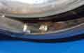
 Even though I used the tool previous 'brute force' had obviously taken it's toll as removing one of Vee's the end of the clip snapped off, but replacements clips BAU1460 are available on only take moments to replace ... once you have removed the lens and reflector, inner bowl from the outer bowl, and the outer bowl from the wing ... Note that once the spring has been detached the inner bowl should rotate off the adjuster screws without needing to remove or alter the position of those screws, which avoids upsetting the beam alignment.
February 2023:
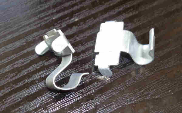 Had occasion to remove the other trim-ring from Vee and that clip snapped off as well. I'd already used both I had bought previously so bought two more, and this time replaced it with minimal dismantling. Once done I found that on refitting the trim-ring it dropped into the notch in the clip as it should, rather than lodging behind it, and came off again with the puller much easier than any of them had before, but still held firmly.
Clearance to wing: October 2021:
 Graham Moore on the MGOC forum has been having problems fitting new trim rings as part of his restoration because there is insufficient clearance to the wing at the inner edge. I've had the same problem on Vee with what are probably original rings, and so has a PO as the passenger side ring is slightly flattened in that area. Measuring old and new rings - the thickness of the flange where it contacts the rubber gasket - Graham's old rings were 2.8mm and new 4.5mm. I have an old set from Bee replaced 32 years ago and they and the original ones on Vee measure 2.6mm. Bee's 'new' ones measure 2.85mm ... at one point but increasing as you go round the rim to 3.45mm! Originals have a welded seam that has to go in the area of the bottom inner corner limiting scope for placing a thinner part by the wing, but modern ones have no weld so can fitted with the thinnest section in the smallest gap. Graham is handy for the MGOC shop and early CB wings (wide spaced sidelights) have plenty of clearance between rim and wing - 3-4mm, all the later ones had less than 1mm. He also spoke to the workshop who confirmed that they never fit later cars, and they need to grind the wing before painting and reduce the weld size right in the corner too, as well as slotting the holes in the bowl so that can be slid across to make more room. As Graham says - Great! Looking at Bee and Vee here is just enough clearance on Bee - about that 1mm Graham mentioned, and on Vee's driver's side, but on Vee's passenger side there is no clearance even having slid the bowl across as far as it will go without grinding the (freshly painted!) wing, and the ring has been flattened in that area as well.
 Whilst only originally provided for North America during the last year of production a number of UK suppliers have the headlamp ring with cut-outs for adjustment meaning removal of the ring is not required. On-car they do look a little 'odd' though.
 And now for the adjustment! By comparison with trim-ring removal it is simplicity itself. The adjuster screw at the top tilts the beam up and down, and the one at the side moves it from side to side. You can adjust the beams without the aid of a beam-setter if you have at least 37ft 8 ½ inches (25 ft plus the length of the car!) of flat and level surface back from a vertical surface such as a wall or garage door. Drive the car up to the vertical surface and mark the position of the centre of each headlight e.g. with electrical or masking tape. Now comes the confusing bit. Various sources now say to place two more marks 3" below the centre of the headlight, or 2", or 1" down and 1" to the left, and others just seem to use the original marks. UKMOT.com has a diagram showing that the datum lines should be 0.5% to 2% down, and 2% to the left, which for MGB headlights typically 24" (Vee) off the ground (i.e. less than 850mm or 33.5") equates to 0.12" to 0.48", and 0.48" respectively! Or is that percentage of the screen width and height!? The junction of the two lines ('break' point here) should be between 0.5% and 2% below the headlight centre, and between 0% and 2% to the left. In the past I have set mine using the centres and they have failed the MOT as being too high, and what has passed puts a pool of light just a few feet in front of the car on dipped beam, and still on the road albeit further forward on main beam i.e. to me too low. So probably better to err on the side of lower rather than higher. The MOT should check them with someone sitting in the drivers seat, so if you do yours with the car empty (beautiful/handsome assistant not being available/willing) that will give you a bit of a margin.
 Back up so the front of the car is 25ft from the vertical surface and turn on the dipped beam (obviously doing this at night is preferable!). Each dipped beam should have a flat and horizontal top edge on the right-hand side, and the left-hand side should be angled upwards, this upward angling lights up the left-hand side of the road. Note that other European countries don't have this which is why they don't need beam deflectors when driving here like we do when driving there. A typical MGB won't have a sharp cut-off at the top of the beam like many modern cars do, having some upward scatter, but there should be a visible point where the horizontal part joins the angled part - the junction. Adjust the headlamps so that this junction is on your secondary marks. Switch to main beam and the centre of the beam should also be on these secondary marks. Note that if your reflectors are cloudy, bulbs old and blackened inside etc. the junction may not be clear enough and it can fail the MOT. Any misalignment of the bulb, reflector etc. could result in one beam to be correctly adjusted but the other not, with the same result.
Headlamp Mounting: January 2017
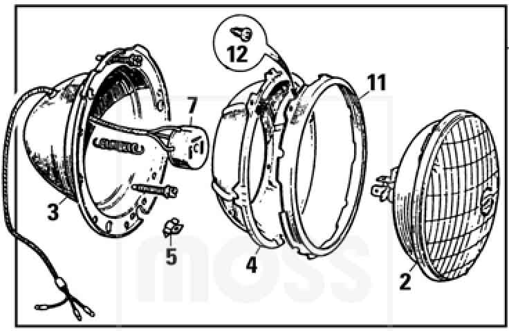
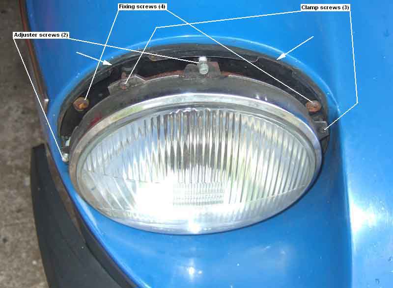
The headlamp glass and reflector (a single unit) is clamped into a chrome-plated surround with four small screws. The rear half of the surround has a tab at the top and one on the outer edge for the special beam adjuster screws to slot into. These screw into nylon sockets fitted into the headlamp bowl, and as they are turned move their part of the surround plus headlamp assembly back and fore to get the correct height and side to side adjustment. The back of the reflector should have a tag with a hole, and a spring goes between this and a similar tag inside the bowl, to pull the headlamp assembly plus clamp ring into the bowl, and it is pushed out against spring tension by the adjuster screws to get the correct beam adjustment.
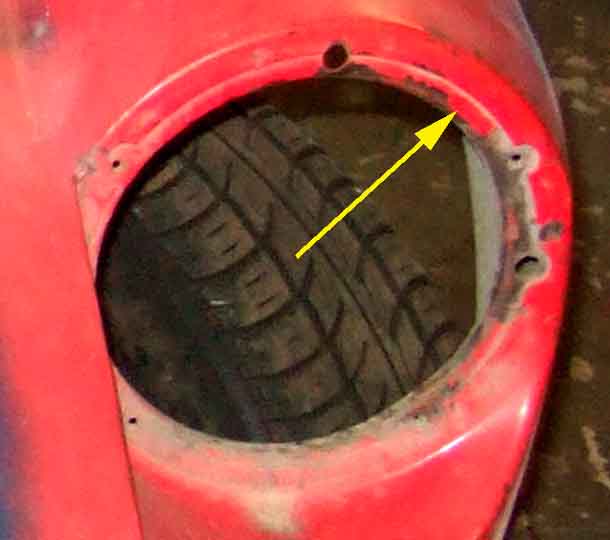 The bowl attaches to the wing with four screws - top, bottom and at each side, with a rubber gasket between bowl and wing. The gasket has sleeves for the adjuster screws, to prevent dirt being thrown forwards onto the headlamp and down the outside of the wing as well as to protect the screws from the worst of road dirt to some extent. The four bowl screws go into a reinforcing/mounting ring which is spot-welded to the back of the main body of the wing. This reinforcing ring does not appear to be separately available for the MGB, but should be the same as the classic Mini item which is part No. 14A6993 from many sources.
Halogen
LED
HID
Relays and Fuses:
Main beam/flasher problems
The full current for the headlights is fed through the main and dip switches. Not only does this involve considerable lengths of wire and several connectors, but ageing switches can be less than perfect, all of which produces less light from the lamps and heat in the switches, in extreme cases melting them and causing total loss of lights. Uprated headlights almost certainly take more current which will make the foregoing problems worse, and you will not see the full benefit of the extra power. Always consider fitting relays with uprated lamps, which will result in more power at the lights and less strain on the old switches and connectors. Two relays will be required - one for the dipped beam and one for the main. The difference can be remarkable, as seen with a set I fitted to a car with uprated headlamps. Beforehand when switching from dip to main and back again there was a finite period when there was virtually no light at all! Afterwards the switch was near instant, and the lights were significantly brighter as well.
The next consideration is fusing. The headlights were never fused by the factory. Because you are adding wiring it does make sense to fuse it, but simply providing one main fuse (e.g. the MGOC and Moss kits) could result in total loss of the headlamps if it should fail, so think in terms of providing one fuse per beam as a minimum if not one per filament. This will protect the wiring from just after the relays out to the lamps, but still leaves the relays and wiring to them unprotected. By positioning the relays close to the point at which you pick up the supply from a brown connection point and properly routing and harness-taping you can minimise the risks but some might still want to fuse the main supply as well. In this case you should use a rating at least double that for the filaments, otherwise a problem by one headlight could blow the main fuse and not the filament fuse. I would recommend using 10amps per filament or 15amps per beam, which is about double the typical current flow, and 30amps minimum for the main fuse. That may seem high, but the headlamp flasher needs to be considered. From 1970 when the dip-switch was on the column stalk the headlamp flasher used its own fused supply, but with relays all that circuit does is operate the main beam relay. If the headlights are on dipped beam and the stalk is pulled towards you to flash the main beams, both relays will be operated and all four filaments will be powered, so any main fuse will be carrying getting on for 20 amps, and needs to be in excess of that. If you are not using a main fuse in series with filament or headlamp fuses then the filament and those fuses can be standard 17/35s.
Click on the link for the schematic ![]() and suggested layout. The standard wiring on most MGB has two double bullet connectors by the right-hand headlight one for dip and one for main. These have three wires - a supply wire and another wire in the main harness that goes across to the left-hand headlight, the third wire from a tail going to the right-hand headlight. At the left-hand headlight there are two single bullet connectors each with a wire from the end of the main harness and a tail leading to the headlight. Early cars have this junction in the middle of the car with two long tails - one to the left and one to the right. Position the fuses close to the relays. One fuse per filament will see four fuses on the output of the two relays, one fuse per beam will see two fuses feeding power to the relay. To avoid cutting into the harness, and to make the changes easily reversible if required, make up a sub-harness that picks up the blue/white and blue/red wires from the main harness via two single connectors and routes them to the relays, two wires from the relays to the fuses, and four wires from the fuses back to four single bullet connectors to join up with the wires to the headlamps.
and suggested layout. The standard wiring on most MGB has two double bullet connectors by the right-hand headlight one for dip and one for main. These have three wires - a supply wire and another wire in the main harness that goes across to the left-hand headlight, the third wire from a tail going to the right-hand headlight. At the left-hand headlight there are two single bullet connectors each with a wire from the end of the main harness and a tail leading to the headlight. Early cars have this junction in the middle of the car with two long tails - one to the left and one to the right. Position the fuses close to the relays. One fuse per filament will see four fuses on the output of the two relays, one fuse per beam will see two fuses feeding power to the relay. To avoid cutting into the harness, and to make the changes easily reversible if required, make up a sub-harness that picks up the blue/white and blue/red wires from the main harness via two single connectors and routes them to the relays, two wires from the relays to the fuses, and four wires from the fuses back to four single bullet connectors to join up with the wires to the headlamps.
October 2016: Relay kits are available from MGOC and Moss Europe (with the latter being a lot more expensive!) or Moss US. Both kits only seem to include a single main supply fuse, which should it blow will kill both dipped and main beams. Daniel Stern Lighting recommends one per relay, and this kit from Advance Autowire has one per filament, but no main supply fuse, so opinions obviously vary! For both MGOC and Moss kits it would be easy to add a second fuse and have one per relay, and not much more work to add one per filament, just by adding in-line fuses with the appropriate spades and bullets. However note that the Moss and Advance kits use relays plugged in to sockets. There are two configurations of relay terminal, and with sockets you have to use the correct configuration, more info here.
November 2020: In the space of a couple of days I was asked for advice about improving the electrics with relays and fuses from two separate people, and a pal in America sent me a picture of heat-damaged wiring at his lighting switch. All of which set me off thinking about Vee's headlights as we do occasionally use her at night.
But first I decided to see just how much difference a relay might make. I took a length of the heavier gauge wire that is used for headlights, put a bullet on one end and fitted that to the spare hole in the main-beam bullet connector by the right hand headlight, and positioned the other end (which happened to have a ring terminal) by the battery terminal post in the engine compartment. Turned on the headlights as normal, then tapped the ring connector on the battery terminal post. Not only did they brighten significantly, but the connection even sparked confirming that significantly more current was flowing, and the voltage at the headlight bullet increased from 9v to 11.5v (engine not running), and that despite my 'ring main' wiring of the brown circuit. So Something Should Be Done.
Relays are simple enough, but what to do about fuses? Two relays plus four fuses is going to take up quite a bit of space on the inner wing, all need mounting, and I don't like drilling holes. You can get sockets for plug-in relays so I looked for a socket for a pair of relays with a single mounting point without success. But along the way I found this dual relay with single mounting point from 12v Planet which is just the ticket - or so I thought. These are unfused and whilst I could get fused relays for individual sockets they take modern blade fuses which means carrying spares. In the end I decided to go with in-line holders that take standard fuses, 20 amp rated with spade terminals also from 12v Planet, and use just one per relay i.e. one for the dipped beams and one for the main, and expect to have the presence of mind to switch beams if the one should fail. I'm planning on having only about 6" of wire from the relay to an existing brown circuit connection. Four of these fuses could be used one per filament if you prefer but you would have to join two together to connect to the relay output, in which case the 'bare ended' type would probably be better for you to attach your own terminals.
Fabrication went well but with five headlight-grade wires going to the two relays I discovered the individual relays were getting dislodged in the dual case during installation. They are 'skeleton' relays, the only casing is the dual case, and they are only 'clicked' in. As well as the risk of mechanical damage I can't see anything stopping moisture getting in and causing problems, so I decided to super-glue them in ... and of course ran out of adhesive and had to order more. But the biggest headache by far was getting them working properly. You need to find the supply wire to the 4-way bullet connector at the right-hand headlight and pull that out, as that becomes the relay 'operate' wire, and the output wire from the relay goes back into the 4-way bullet connector to power both headlights. In theory one pulls one of the main harness wires out, and if both sides stop working you know you have pulled out the supply wire, so you put that into a new 2-way bullet connector with the relay 'operate' wire. But if only the left-hand headlight goes out you have the wrong wire, so put that one back and pull the other one out. Easy, no? No! I just couldn't get them to work right - one beam worked but not the other, sometimes one of the relays buzzed, if the dips were on and pulled the stalk back to flash the dips went out and all sorts. Thinking I had the wrong wires I juggled them about which just confused the issue. Resorted to a 12v jumper lead to operate the relays and power the lamps directly to try and work out what was wrong to no avail. Got a meter to measure the voltages and got some very strange readings. Eventually I used the jumper wire to connect an earth to the relays on top of the existing earth wire, and suddenly they started working. When I removed the front fog/spot lights for painting and decided not to put them back I left the relay in place with just the earth wire connected having removed the other three wires. Mounting the dual relay in place of the single I simply swapped the earth wire over to the new relays 'assuming' it was a good earth ... and of course it wasn't! Testing it with an ohmmeter it drifts about a bit, it comes out of additional wrap on the harness so where it goes back to I have no idea. All I can say is that the old lights worked - probably because it was just one relay, but two sharing a poor earth get unwanted interactions. Anyway, I abandoned that wire and fabricated a new one to go under the relay fixing screw. Phew.
At the same time I've decided to uprate the H4 bulbs to Osram Night Breaker Silver which are claimed to be about 100% uprated (see below). Incidentally, one person reviewed these bulbs and complained about them giving an 'amber' light instead of 'silver' as on the tin. The word 'dipstick' comes to mind.
Main beam/flasher problems: October 2021 Note that if your speedo contains the main-beam tell-tale as well as the panel light bulb the speedo must be properly earthed. Brian Wall on the MGOC forum reported a strange problem affecting the headlamp flasher after doing some work on his relays. It took a couple of goes to ascertain what was happening but I suspected speedo earthing affecting the main-beam tell-tale. The first symptom was that if the tell-tale was unplugged the headlights worked as they should, and if the tell-tale bulb holder was earthed with a separate wire that also worked as it should. Subsequently Brian wrote "when I turn on headlights it will show main beam and allow me to change to dip beam, but then will not change back to main or even flash the lights (unless I) turn lights off, then on again and same sequence all over again, until I disconnect the telltale and let it hang free and then the headlights and flasher work as normal". This confirmed speedo earthing as the problem to me, and connecting an earth to the speedo allowed everything to work as it should, The problem occurred for the following reasons:
- With the parking lights on, the lack of earth to the speedo means that the panel light is trying to earth backwards through the main-beam tell-tale bulb.
- Without relays the two bulbs in series would earth through the headlamp main beam filaments, but the current is so low you would not notice it at the headlights. Both panel and tell-tale bulbs would only glow dimly - unlikely to be noticed especially in daylight.
- With relays the relays only supply power to the headlamps themselves, the main-beam tell-tale is powered from the dip-switch/headlamp flasher switches as before, which are also powering the main-beam relay, hence there is a connection between the tell-tale and the relay winding.
- When the main beam is turned off there is enough current flowing from the parking light circuit through the panel light bulb and backwards through the tell-tale bulb in series to the relay winding to keep the relay operated ... unless the panel light dimmer is turned off!
- This keeps the main beam illuminated, but again you would have to look closely to realise it unless you were in the dark, especially if the dipped beam was illuminated.
- The headlamp flasher used on its own, i.e. with the main lighting switch off, would almost certainly work normally. Even the tell-tale would work almost normally as current from the headlamp flasher switch would flow through the tell-tale bulb and backwards through the panel light bulb to the parking light circuit, and from there to earth through all the parking light bulbs in parallel, again unless the panel light dimmer switch is turned off.
- LEDs used in panel lights and/or the tell-tale would change the symptoms because they will only pass current in one direction, not both like a filament bulb. LED headlamps were in use on this car but I don't think they would have an effect, and relays shouldn't be needed with LED headlamp bulbs anyway as the current is much lower.
Halogen: If you have sealed beams currently you will need an H4 conversion which includes the headlamp unit as well as bulbs, the connector should be the same. One would hope that these kits are correct for the MGB but some headlamp units are too deep to fit in the bowls.
Uprated halogen: There are H4 halogen bulbs available with claimed 20% to 200% more brightness for the same wattage as originally e.g. 60/55W, all road legal. There are also 100/80W and 130/100W versions for sale, but unless they were original equipment on your car they are not road-legal. The 'brighter for the same wattage' bulbs achieve that by a different design of filament which draws the original current, and hence are the same wattage (Watts being Volts multiplied by Amps), but as with anything else you don't get owt for nowt and the 'cost' (in additional to higher price) is a shorter life. For example the 150% is said to have half the life of the 130%, which itself will have a reduced life from the 110%, and so on comparing 110%, 50% and standard. When buying these make sure they are dual-filament for main and dipped beams, as there are single-filament variants which have the same H4 fitting. They are for cars with dual headlights such as the ZS which has main and dip in the outer headlight, and an additional main beam only in the inner headlight. As ever shop around, for example Halfords has a single 50% brighter at Ł17 (although you may get a BOGOF offer), whereas Euro Car Parts has pairs of Osram 115% at Ł15, Phillips 130% at Ł18, and Phillips 150% at Ł21 (although with these last two there is no written indication of whether they are single- or dual-filament). Standard halogen dual-filament are typically Ł3!
November 2020: As part of installing relays and fuses I also purchased a pair of '+100%' uprated bulbs but as the detailed text says 'up to' that can mean anything or nothing. After fitting just one it's true they are a bit brighter - but not as much improvement as from the relays, I doubt you would notice the difference with two in and on the road. But they were reduced from Ł17 to Ł12 so I can live with that.
But before considering a change such as this, it would be best to investigate your switches and wiring to see how much voltage is being lost before it gets to the bulb, if not fit relays and fuses. Clean bullets and connectors always help, and you should consider replacing the connectors at the front of the car, polishing the bullets with fine wet-and-dry or emery cloth, and reassembling with Vaseline. I did that on Vee as a matter of course towards the end of her restoration, as well as polishing all the bullets by the pedal box and in the boot, and found the indicator flashing rate afterwards was noticeably faster and more consistent even though the switches and wiring were as before. To measure the volt drop connect a meter between the brown at the fusebox, and the back of each of the bullets by the off-side headlight, for each beam when powered. No need to run the engine, although the voltages you will see will be higher the relative differences will be the same, and it is those we are interested in. There should be two wires from the harness, and one wire from the sub-harness going through the inner wing to the headlight. Any difference in voltage between the three bullets shows that voltage is being lost in that connector. And the difference between the highest of those and the brown at the fusebox is what is being lost in the main lighting switch, dip-switch, and their wiring. You can also unplug the alternator, and move the meter probe from the brown at the fusebox to the thick brown in the alternator plug, and the difference between that and the fusebox reading will tell you if any is being lost in the connections at the solenoid. Unless you have brand-new wiring and switches, and perfect connections, you are bound to see some voltage being lost, in which case your headlights would benefit from having relays and fuses installed. I fitted relays and fuses for someone with (illegal) 100w bulbs, he said before that as well as not being very bright before, when switching between dip and main the 'new' beam only gradually came up after the 'old' beam went out, leaving him momentarily in the dark. Afterwards he said they switched almost instantly, as well as being noticeably brighter. Checking Vee main beam lost volts is about 1.8v and dipped about 1.5v, with Bee (old bullet connectors at the front) a couple of tenths higher. There is only about 0.1v difference between the fusebox and the alt plug on both. Powered normally, then adding a thick jumper wire between the fusebox and the connectors (simulating a relay), there was a visible increase in brightness. Pondering.
LED:
March 2023: The wording changes again to remove the confusion caused by the use of the word 'halogen', now conversion to LED or HID of any type of headlamp on cars first used before 1st April 1986 is legal.
March 2021: Ink barely dry and they change the rules again. From 22nd March halogen to LED conversions on cars first used before 1st April 1986 will be legal. But then they go and mess it up by writing:
"Vehicles presented with converted halogen headlamp units first used on or after 1 April 1986 will continue to be failed."
Also by specifying 'halogen' it's implying converted sealed beam installations will continue to be failed, surely 'halogen' should read 'incandescent' or 'filament' i.e. treat sealed beam and halogen the same. Even more complicated where sealed beam have already been converted to halogen!
Even more interesting is that HID conversions will also be legal, and having been disappointed with an LED conversion I'll be looking at HIDs.
1st January 2021: MOT rules have been changed to fail cars with LED headlamp conversions:
4.1. Headlamps
4.1.4. Compliance with requirements
"Existing halogen headlamp units should not be converted to be used with high intensity discharge (HID) or light emitting diode (LED) bulbs. If such a conversion has been done, you must fail the headlamp."
October 2020: Information on legality or otherwise from Classic Car LEDs and the Federation of British Historic Vehicle Clubs here.
September 2020: Brian Wall on the MGOC forum asked about his club-supplied LED headlights and why the headlamp flasher wasn't working when the dipped beams were on. I wondered whether this was something to do with having LEDs and asked if the tell-tale was coming on. It is, so yet another undocumented feature of dual 'filament' LEDs. However Brian raised this again in November 2021 after having rewired the relays, and this time I suggested he double-check that the dip relay is remaining operated and the main relay operates as well when the control is pulled to flash. And he discovered that he had cross-connected the two some how, and correcting that they work as they should.
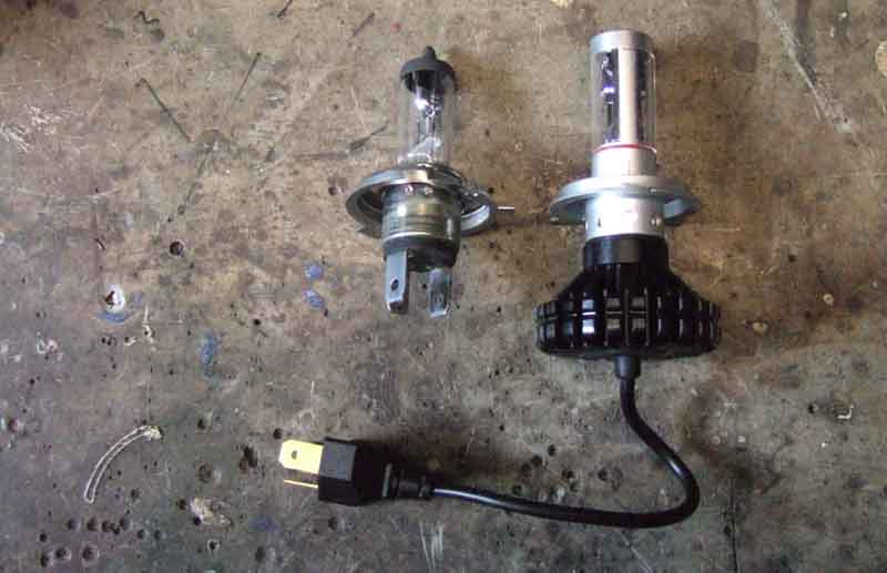 Intrigued by an advert in Enjoying MG I did some research and found some with the same manufacturers designation elsewhere at about half the price. They turned out to be slightly different physically as the driver module is integral with the lamp, which has a short cable terminating in a 3-pin plug which is compatible with the harness socket. There is quite a large 'lump' on the back of the 'bulb' which made me wonder if it would all fit in the bowl, but it did. The MGOC items are shown with an external driver module, as well as having the lump on the back and cable with plug so even more to fit in.
One issue with installation is that you install the H4 adapter to the reflector/lens assembly, then slide the 'bulb' into the adapter, and twist it to get the correct beam pattern with a ball-bearing dropping into a hole to hold it in the selected position. This is so that one kit can be used for both RHD and LHD with the upsweep on the correct side ... but there are a whole series of holes all round the adapter meaning you can select any of about a dozen positions, including with the beam vertical instead of horizontal! The 'issue' was with the rubber seal that fits round the base of a halogen bulb and pushes up against the back of the reflector. With the LED items you fit the rubber seal to the back of the reflector after the H4 adapter, then push the LED 'bulb' through the hole in the seal into the adapter. However the seal is too deep to allow the 'bulb' to go in far enough for the ball-bearing to engage with one of the holes, meaning it (the seal) would have to be cut down. I didn't do this, pending further enquiries.
 As far as adjusting the rotational position of the 'bulb' goes this has to be done with it powered, but before the lens/reflector is clamped into its carrier. The flat and angled cut-offs of the dipped beam can be clearly seen in the glass, and as my glass has similar moulded lines, it is a simple matter of turning the 'bulb' until the edges of the beam line up with the mouldings in the glass. Bear in mind that when looking at the glass, everything is reversed compared to how the light strikes the road, i.e. the light is at the top of the glass instead of the bottom, and the angled section is on the off-side instead of the near-side.
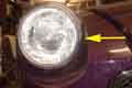
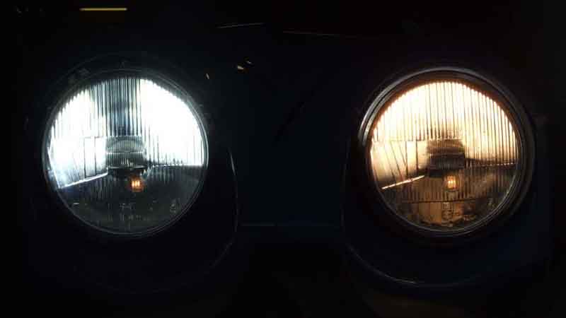
 That gives rise to another 'issue', and that there is a distinctive 'dead' area in the light at the top of the glass, which means there will be a similar 'dead' area on the road right in front of you. This can be seen in YouTube demonstrations of other LED installations on other vehicles, and isn't apparent with halogen bulbs or sealed-beam units. The light is very white, and makes the filament pilot light in the rubber-bumper headlamp assembly look like an orange neon. A brief test at night in lit streets didn't seem to give that much better actual visibility, it was more the whiter reflection.
Yet another issue was flickering. A pal has had two sets of LED stop/tail but they failed the MOT being 'adversely affected by the operation of other lamps' i.e. flickering when the (filament) indicators were in operation. Some have said that is a factor of cheap bulbs, and if you pay more for better quality from other vendors it doesn't happen. One such vendor was named, and this is who I got my LED headlights from. Interested to see what happened when I cranked the engine with them on, I couldn't help laughing out loud when they cut out altogether apart from very brief flicks of light. There was also a visible flicker when the indicators were going - so much for 'better quality'.
However the biggest issue (at the time, clarified and simplified since) concerns legality. It wasn't until I got them that I saw on the box 'OFF-ROAD USE ONLY', despite the vendors description including words such as 'as used on our cars' and 'not dazzling other road-users'! So I did a search for 'off-road' in their ad and found buried in 2537 words of Terms and Conditions the statement "... Therefore all our external LED bulbs are sold as off-road use only." The MGOC ad makes no mention that I have been able to find, and speaking to them it is a grey-area. 1986 Regulations state that cars first used from 1st April 1986 must have filament lights with an approval mark, which is fair enough. But for cars used before that there are contradictions with the UN accord of 1958. The upshot is that pre-1/4/86 it's not clear (no pun intended). You are unlikely to get stopped by the Police, and the MOT only checks function and adjustment not legality, but that still leaves your insurance company. I consulted mine, and they were quite clear that they did not approve them, and it could compromise any insurance claim even if I had advised them beforehand. I'm pretty sure he knew what he was talking about as he was a Land Rover enthusiast and said there were LED conversions for Defenders with 7" lights which were legal. He gave me the details of two types (Nolden 7" Bi-LED and Lynx Eye) but these are so aesthetically different (and expensive!) compared to the MGB originals they are out of the question. The upshot is, these LEDs go back, and uprated (brighter but same wattage, higher wattage also being illegal) halogen are next to be tried.
The doubt over the legality of external LED lighting has cropped up before on MG fora, and many pooh-pooh it. But that's up to them and you. If you make an informed decision to fit them and it goes wrong, you have no-one to blame but yourself.
February 2024:
 Pal Geoff had bought an MGB with complete LED headlight units (similar to Nolden and Lynx above) that have DRL and indicator functions as well but wanted to go back to standard headlights, which was where I got involved, and that made the LED units surplus to requirements. He offered them to me but I wasn't interested (at the time ...) having already fitted HID and then quite by chance not long after someone else contacted me seeking advice about improving headlights as he was getting less and less comfortable driving Yorkshire lanes in the dark. I mentioned these were available, sent him a link to similar lights (not knowing exactly where Geoff's had come from), he was interested, asked if Geoff had any comments about performance which he hadn't as he had done no night driving, so I offered to do some comparison tests. As well as the LED unit I have my previous 10% uprated halogen 'on the shelf' and the HIDs in the car. I'm not going to swap headlights round on the car, but can do 'hand-held' beside the car pointing down the road. Done from the garage as I'm not prepared to take all the gubbins out to a dark lane, so it is subject to local street lighting, which does include one immediately across the road. Set the camera recording, took the HIDs first, then each of the other two. The LED unit was quite impressive, although not as good as the link I had sent indicated, but noticeably better than the LED 'bulbs' I had tried, the halogen 'live' was pretty dim in comparison. Using basic jumper wires to power them and hand-held I wasn't able to switch the other two between dip and main while keeping them steady, so did some editing of the video afterwards trimming and splicing to get the same effect. Recorded - subject to the street light immediately outside - and played back the halogen was so weak I didn't bother including it, and the LED was nothing like the link portrayed, and nothing like the HID (it's always annoyed me just how low headlight beams have to be to pass the MOT compared to OEM HID, which when on SUVs, 4x4s and the like are shining right in the eyes of an MGB driver ... even an RB MGB!). There is a wide range of LED units available, ranging in price from Ł25 to Ł500, so how you choose between them I don't know.
HID: March 2023: The wording changes again to remove the confusion caused by the use of the word 'halogen', now conversion to LED or HID of any type of headlamp on cars first used before 1st April 1986 is legal.
March 2021: Ink barely dry and they change the rules again. From 22nd March halogen to LED conversions on cars first used before 1st April 1986 will be legal. But then they go and mess it up by writing:
"Vehicles presented with converted halogen headlamp units first used on or after 1 April 1986 will continue to be failed."
Also by specifying 'halogen' it's implying converted sealed beam installations will continue to be failed, surely 'halogen' should read 'incandescent' or 'filament' i.e. treat sealed beam and halogen the same. Even more complicated where sealed beam have already been converted to halogen! Nevertheless as Vee IS halogen and we do use her at night I decided to look into a conversion.
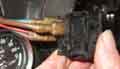 Only three wires but still several permutations even with only three spades as on rocker and the later 'toggle' switches on the column cowl. Early push-pull and toggle switches can have several unused spades and also work either way up, although there should be a flat which ensures they cannot turn in the dash as well as meaning they can only fit one way round. If the terminals are numbered then brown should go on 4, red on 7 and blue on 8. Rocker switches can fit in the dash either way round but forward-facing lamps have the logo pointing to the right. Later illuminated rockers fit with the illuminated panel at the top. You can derive the connections by using an ohmmeter as follows:
- When off all three spades should be isolated.
- In the first operated position two spades (pins on later toggle switches) will be connected together, brown and red can go on these either way round.
- In the second operated position a third spade/pin will be connected to the other two, blue goes on here.
Prior to 1977 models the main lighting switches were always on the dash, after that they were on the steering column cowl. The cowl wiring has been known to get trapped and cause short-circuits, which can damage wiring as well as the switch. North American spec Mk2 prior to 1970 had the panel light on/off (not a dimmer) switch on the column cowl and those wires can also get trapped. None of the lighting wiring is fused at that point.
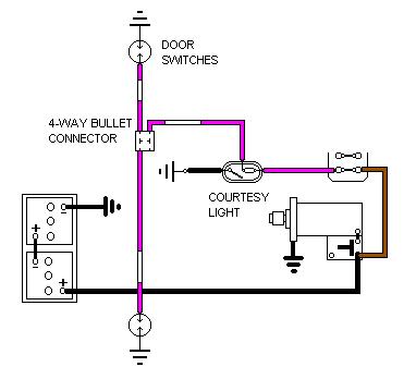 A simple 'lights on' warning buzzer when a door opens which avoids having to cut one of the courtesy-light switch wires, but operates from the passenger door and manual switch on the courtesy light as well. By cutting the purple-white to the drivers door switch a diode can be inserted so only the driver's door operates the buzzer. The polarities of the diode(s) and buzzer assume a negative-earth car, they should be reversed for a positive-earth car. Any 100v, 1 amp diode and 12v dc buzzer should suffice.
Added April 2010:
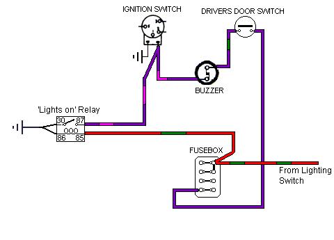 I've been asked by Frank Mooring if it's possible to use the existing North American spec seat-belt and 'key in' warning buzzer for a 'lights on' warning, rather than provide an additional buzzer. I suggest schematics (click the thumbnail) for each of the three types although I haven't been able to test them. This requires the use of a relay to convert the light-on signals so they can be used by the existing circuit. It may be easier just to provide and additional buzzer, but this will need a diode as shown in the schematics above.
Daytime Running Lights (DRLs):
Legally, there seems to be no information regarding after-market DRLs, and even that for later vehicles where they are original equipment is sketchy to say the least. The MOT Manual Section 4.2 (Updated: 14 October 2021) says they are only inspected on vehicles first used on or after 1st March 2018, and the only mandatory information for those is that they must go on and off with the engine. Other than that "Daytime running lamps (DRLs) or headlamps may function as front position lamps. If the DRLs function as front position lamps, they may or may not dim when rear position lamps are switched on and may dim or turn off when headlamps are switched on". They are not mentioned in the Categorisation of vehicle defects for passenger cars, and I can't find any mention of lighting at all in the Construction and Use document ... which is because it is covered under the separate Road Vehicles Lighting Regulations, which says even less than the MOT Manual.
LEDs are the obvious choice for longevity and low power consumption. I spent some time looking at these, but for after-market you are looking at spending Ł50 upwards without knowing anything about how they perform. Avoid cheaper 'styling' lights, they use much smaller and less bright LED elements. I even pondered OEM types as at least one can see those in use on our streets, but usually they are highly 'styled' for integration with existing bodywork on the car in question and not suitable for aftermarket use - round MINI types being an exception, but they are going to cost a fortune, maybe even at a scrapper.
Which led to the next question - circular or strip? I did find some cheap circular 9-element ones that fitted quite neatly to the honeycomb grille, but they were just not bright enough. Then after a long time with occasional searches of the internet I came across these Eagle Eye LEDs. Reputedly 9 watts (although I've never been able to get a clear explanation from any supplier of just what wattage means as far as LEDs go) and with a lens at 13mm diameter (overall housing diameter 22mm) much bigger than anything else I had seen before. At Ł2 (free P&P) for a pair on a slow-boat from China it was definitely worth a punt and when they sailed (OK, that's enough) through my letterbox a couple of weeks later the good news was that they were very bright indeed across the whole of the lens area, I couldn't look into them, definitely suitable. The bad news was that one of them didn't work. But an email to the vendor elicited a very polite apology and another pair sent. Take care when considering other suppliers, some of which supply in larger quantities with a lower unit cost, as there are smaller, and less powerful, versions around e.g. 3W types at 13mm overall diameter. Read the descriptions and look at the images carefully - compare the overall and nut/thread sizes, this supplier was the only one I could find at the time with this physical size and power that would ship to the UK. There were also more expensive suppliers, but for identical items, so simply paying more for the same thing. Some of these are probably based in the UK, so you would get them quicker, but for a new project I'm of the opinion that time is less important, unlike for something that has broken and needs fixing as quickly as possible.
Next thing to ponder was quantity, mounting and positioning. Four each side should be enough, I know many OEMs go silly with a couple of dozen, but four each side is quite common and should be fine, so order three more pairs. These are individual LEDs, with an aluminium threaded body and nut, and the cable coming out of the back. The threaded part would fit through the holes in the honeycomb grille, so vertically at the outer edges is a possibility. But the grille is tipped forwards slightly, so each LED would need to be angled to point forwards (I had a similar problem with the round ones) individually, or a row of them on some kind of a strip held forward from the grille at the bottom. Then there is the question of weather. With the best will in the world even though intended for car and motorcycle use they are not going to be completely weather-proof. The (very thin) cables do go through a rubber grommet into the back of the threaded part, but who's to say that's enough to prevent water getting in? So I decided to mount them in a box. Given the size of a box needed to accommodate the threaded part, that precluded fitting them in front of the grille as they would project forwards far too much. So horizontally under the bumper it is, there is enough depth to the valance for the box, and it can be mounted to the bumper iron that is immediately below and behind the bumper in just the right area.
The box was the next thing - long enough for four across, high enough for the 23mm overall diameter of the LEDs, and deep enough to accept the 30mm threaded part and the cable that comes out of the end. After some searching Maplin has just the job at 112mm x 31mm x 62mm. I'll need two, but order just one to start with for proof of concept. Carefully marked up and drilled the holes (10mm) - pilot first, then stepped hole cutter step by step so I could make sure I was still correctly aligned and evenly spaced. Slotted in the LEDs, fitted the nuts - and a moment's panic as I realised I hadn't taken the internal pillars for the lid screws into account when setting the spacing! Fortunately there was just enough room to turn the nuts on the outer pair. I used silicone grease as a sealant between the LED flanges and the face of the box.
Internal wiring: Next job was to join the four cables together inside the box, and bring a single 2-wire cable out. As mentioned the cables are very thin, with the individual wires and conductors even thinner, so care needs to be taken when joining the four pairs of wires to the stouter external cable and to give mechanical support to the whole assembly. With the five wires in each connection soldered together, and heat shrunk, I turned the joins back against the sheaths of the four cables and slipped another piece of heat-shrink over the whole thing to remove any mechanical stresses from the joins. The external cable was two-wire black sheathed as used on many mains electrical appliances these days, in stock from having been chopped off various dead electrical appliances in the past. I have mounted the box with the lid on the bottom so lying water won't be able to run into the box, but this also allows me to get into the box without removing the box from the car should that be required. I also daubed silicone grease around the join between lid and box and in the screw recesses.
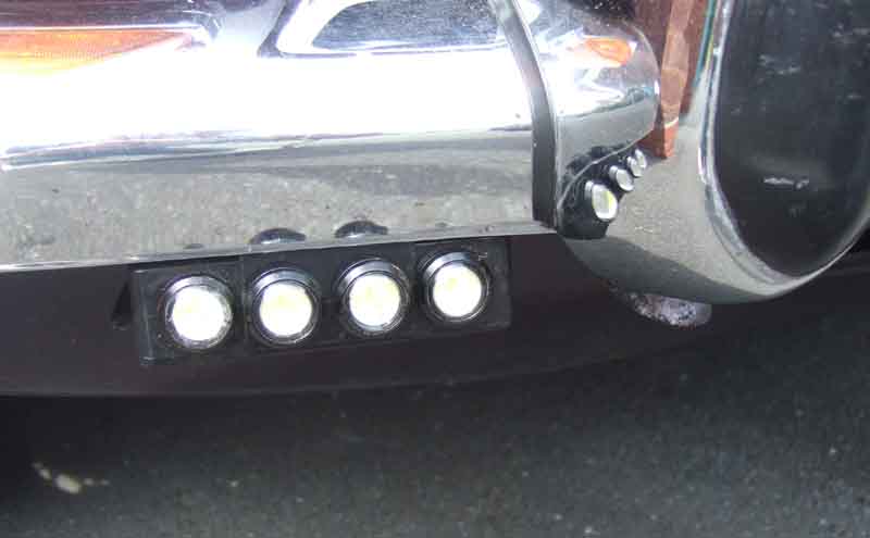 Mounting to the bumper iron was the next consideration, and I decided on a strip of black plastic cut from some square-section down-pipe, under the centre two LEDs, to go up between the iron and the bumper and hook over the top of the iron. If needs be a strip of double-sided foam tape (e.g. number-plate tape) could be used to stick the faces of the strip and the iron together. I've not taken the bumper off since the restoration 25 years ago, but the six nuts came undone easily (courtesy of always reassembling everything with Waxoyl or copper-grease) and I carefully lifted off the bumper, badge-bar and number plate complete. I'd previously measured how far it was from the top of the bumper iron to the bottom of the bumper, and that gave me where to bend the mounting strip to hook over the top of the iron. It only need bending into a right-angle, with a short overlap, as the bumper is close enough to stop it coming off again. Hooked the strips over the iron, and refitted the bumper. When fully tightened the back of the bumper is close enough to the top and front of the iron to grip the strip firmly, no sticky strips needed.
Connections to each other and existing wiring: There is a convenient space at the lower outer corners of the grille surround to fed the cable through, but not very big, so the connectors to join them together and whatever I use to connect them to the cars wiring need to be small. In the end I settle for standard bullets and connectors, even though they are less than ideal for behind the grille i.e. exposed to the weather. But Vaseline used to aid insertion will keep moisture out. I use four-way connectors, to join together the two cables from the DRLs, plus the wires to connect them to the cars wiring.
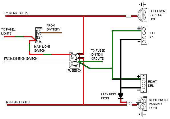 After-market DRLs seem to come with a box of electronics so that they only come on once the engine has started and is charging and the main lights are off, and go off when the main lights are turned on. If you were using 100 watt filament DRLs then I could see the point of not powering them until the engine has started, so taking a significant load off the battery during cranking, but these are LEDs with very low current consumption (30mA for eight). Also reckoned I wouldn't need any relays or electronics to switch them off when the main lights (parking or head lights) are turned on. Like any other light DRLs need positive and negative connections. Positive is easy - just connect to an ignition supply, but for the negative I used a bit of lateral thinking. I simply replaced the 2-way bullet connector for the right-hand front parking light with a 4-way connector and plugged the negative wire from both DRLs into that. How can that work? With the main lighting switch off, there are four parking lights, at least two number plate lights and at least four panel lights (depending on the setting of your rheostat) each going to earth i.e. all connected to earth in parallel, which with filament bulbs gives a relatively low resistance path to earth. Connecting the LEDs to the parking light wire the LEDs can 'see' the earth through the parking light bulbs, and you end up with a potential divider. With the relatively high resistance of the LEDs in series with the relatively low resistance of filament parking light bulbs, with a 12v supply you end up with 11.75v across the DRLs and only 0.25v across the filament. This means the DRLs effectively glow at full brightness and the parking light bulbs etc. do not glow at all. Note this is with filament, with LED parking and number-plate lights the DRLs would probably be a little dimmer and the parking lights might glow a little, as less voltage would be across the DRLs and more across the parking LEDs due to the changed resistance characteristics in the potential divider.
To extinguish the DRLs with parking or headlights on, when the main lighting switch is turned on with the ignition on, you now have a full 12v connected to the parking lights, which results in 12v both sides of the DRLs, which means they are extinguished (same principle as the ignition warning light when the engine is running).
That leaves the situation of having the main lights on with the ignition off, which would result in 12v being connected across the DRLs but with reverse polarity, which LEDs Do Not Like. So I included a blocking diode (1N4001 or 1N4002) in the wire that connects to the parking light connector, which prevents that reverse current flow.
I also connected the DRLs to the green circuit i.e. fused ignition instead of the white, so if there is a short in that wire it would just blow that fuse. And if the DRL wire connected to the parking light connector should short to earth, the parking lights are fused so again preventing damage to any wiring. On early cars with unfused parking lights you might want to use an in-line fuse as well as a diode in the parking light wire.
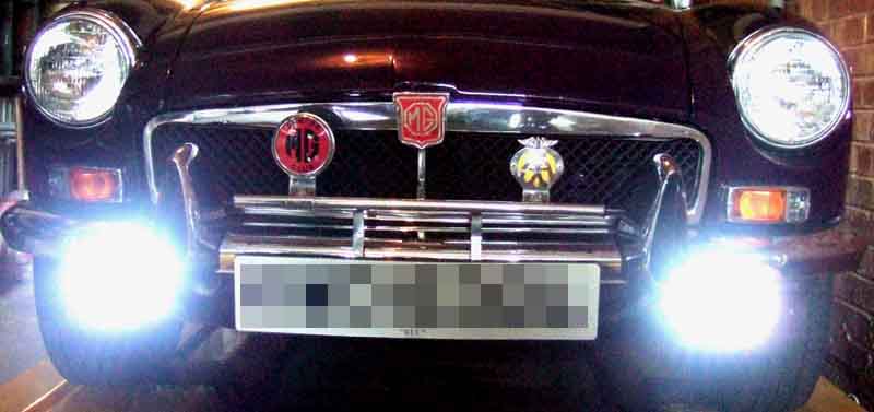 The result is very visible, especially in low light, and anyone who misses these shouldn't be driving.
Switches
|
LED park/stop/tail lights |
|
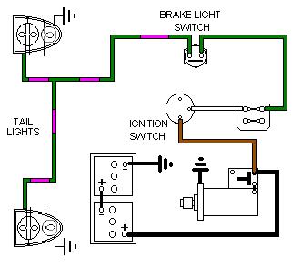
Switches:
Switch failures
Switch relay
Hydraulic to mechanical conversion
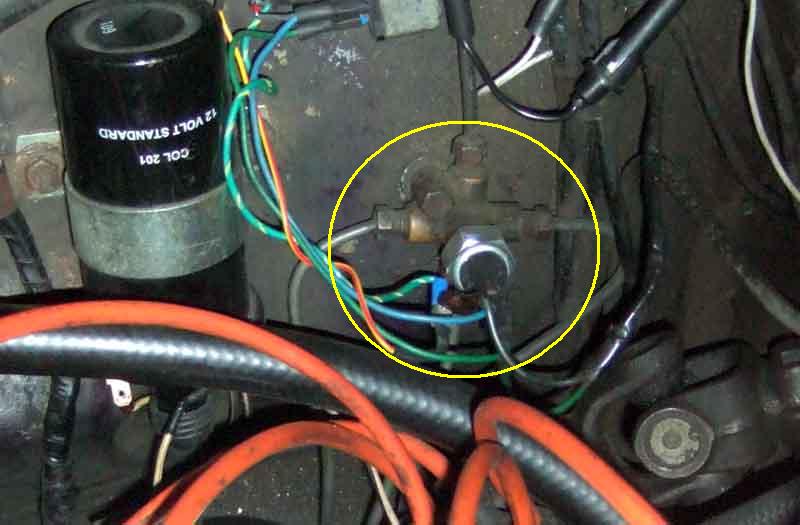 All Mk1 cars, and all RHD chrome bumper cars, use a hydraulically operated switch in the junction on the inner wing near the fusebox. Early switches 13H2303 had screw terminals, later switches C16062/SMB422 use 'Lucar' or spade terminals. Replacement switches of this type seem to be problematic in that they cannot handle the load of the lights and premature failure is often reported, sometimes just after a few weeks, with subsequent replacement no better, meaning either a slave relay has to be installed or conversion to mechanically operated switch is needed. Note that these options are usually only needed if you have the hydraulic switch in the brake pipe manifold on the inner wing, not the mechanical switch fitted to the pedal cover or frame.
 North American Mk2 cars in 1967 had a dual-circuit system - without a servo - with a mechanical switch (BHA4675) on the front of the pedal box. RHD Rubber bumper cars up to September 76 had the same arrangement. Also reported (but less common) are complaints that replacement switches of this type can spring apart because the crimping of the metal part onto the insulator isn't good enough.
For the 1975 model year North American cars got a dual-circuit system with a combined master and servo, and the same mechanical switch was moved to the back of the pedal box. RHD cars got this system for the 77 model year on.
Note that in the 77 and later Leyland Parts Catalogue - Servo System - Dual Line Brakes item 22 is listed as 'BHA 4675 - Switch - stop lamp' but the drawing depicts the brake balance switch mounted under the servoed master.
The mechanical switch needed to change position when the combined master and servo was fitted as the brake master faces the other way. Originally the pedals were pivoted below the push-rod, which was mounted at the top of the pedal, and as the pedal was depressed the push-rod was effectively pushed towards the driver, so the switch could be mounted in front of the pedal in line with the push-rod. But with the combined master and servo the unit is so long it has to face into the engine compartment. This means the push rod has to be pushed away from the driver, so the pedal is now pivoted right at the top, and the push-rod is lower down. Consequently the switch now has to be behind the pedal, again to be near the push-rod. More info on the boosted dual line pedals and pedal box here.
The hydraulic switch only lights the brake lights when a certain amount of pressure has been developed in the hydraulic system i.e. the brakes are already being applied. But the mechanical switches light the brake lights almost as soon as the pedal starts moving, i.e. before the brakes start to be applied, and so give an early indication to following cars that one is about to brake. The hydraulic type are not adjustable, and the usual mode of failure is that they need more and more pressure before the light they lamps fully under light braking they may only illuminate dimly or not at all, but can also extinguish the lights under heavy braking. I've read one report that one of these has also stuck on.
The mechanical type are adjustable and it is critical to have them correctly adjusted. These switches are of the 'normally closed' type i.e. when the pedal moves away from the switch to release it its contacts close and the brake lights come on, and it is only when the pedal is released and operates the switch that the contacts open and the lights go off. If the switch isn't screwed in far enough the brake lights will be on all the time. But more importantly if the switch is screwed in too far it can stop the pedal returning all the way, which can block the bypass port in the master cylinder causing the brakes to stick on as the fluid heats up and expands. Adjust the switch to give about 1/8" free play at the pedal footpad. This free-play must occur at the pedal to master push-rod pivot - impossible to see with the cover on, and impossible to measure with the cover off for the pedal-cover mounted type! Maybe the answer is to screw the switch out until the lights stay on all the time, then screw it in counting the turns and being aware of the free play, until the switch starts moving the pedal down on its own, then unscrewing the switch half the number of turns you counted. I must try it one day ...
Updated November 2009:
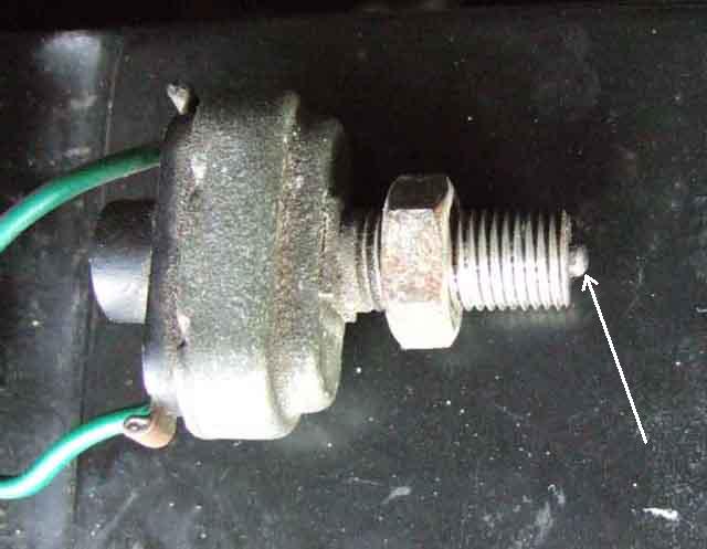 With the mechanically operated switch on the V8 I was surprised just how little movement of the actuator rod is possible - just 73 thou measured at the switch and one and a half turns between the light just going off and starting to reduce the free-play at the pedal. This shows just how careful you have to be, although setting it at three-quarters of a turn further in from the light just going off gives a good tolerance. I found mine at just one quarter of a turn, which is cutting it a bit fine. Out of interest when reset to three-quarters of a turn this gave nine and a quarter turns to remove the switch, but will vary greatly from car to car depending on the dimensional tolerances of pedal, pedal frame, pedal cover, master push-rod and all sorts.
Switch failures:
Protecting the switch with a relay
Hydraulic to mechanical conversion October 2018:
Earlier systems with the hydraulically operated switch worked well enough when new, although after many years they can require more and more pressure before they light the lamps and you may not be aware of that from the driving seat. One way is to look in your mirrors when stationary for the reflection from a car stopped behind you, particularly at night, or when backed up to garage doors, a wall etc. Alternatively you can probably tell simply from the indicators or heater fan slowing down slightly when you press on the brake pedal, especially at idle or with the engine switched off.
Electrical failure of the mechanical switches seems to be virtually unknown even though significantly more than 50% of MGBs used them. Plungers can apparently stick if the car is not used for a long time, but once they are replaced the current Lucas ones apparently have a habit of springing apart as the metal can is not crimped onto the plastic part that carries the terminals anywhere near as firmly as the originals.
There have been claims that using silicone fluid causes the hydraulic switches, even new ones, to fail within a very short time. Certainly from my telecom days, silicone grease was death to contacts, being a very good insulator even resisting the rubbing action as the contacts close. However it now seems that the real culprit is poor quality replacement switches failing in a very short time. If you cannot get an OE (original equipment) switch or NOS (new old stock) you may need to fit a relay to take the load of the lamps off the switch. The relay will need a quenching diode or varistor as even the back EMF generated by the switch releasing the relay seems to be enough to cause the switch to fail. The later mechanically operated type cannot suffer from the silicone fluid problem of course, but if they suffer from the same premature failures as the hydraulic type (and I've not heard of any so far) the same relay circuit can be used for these as well. Alternatively you could fit a generic switch such as this 'pull-on' type seen at Stoneleigh which can replace the pedal return spring and is screwed to the underside of the engine-compartment 'shelf' in an appropriate position, or use a suitable micro-switch with a normally-closed contact off the pedal as I have done here, as well as Herb Adler. Bear in mind generic switches must be capable of tolerating the inrush current of your lamps, which for conventional filament bulbs is significantly more than the current when they are fully lit, for the following reason:
July 2013: Two years on I'm noticing quite a bit of retardation before the tell-tale comes on, and even then it is only coming on dimly until I press the pedal more firmly - not good. After our return from the Surrey Run I connect the relay that I made up two years previously, and I find that the lights are now coming on cleanly, and with the pedal about an inch higher than before, so significantly less pressure, and much lighter braking. Contact the MGOC describing the problem and asking if they are aware of problems with this switch and get the reply: "Thanks for your enquiry, unfortunately this is charactertic (sic) of this brake light design and why it was redesigned on the later cars to a mechanical system. The hydraulic switch does require extra pressure to ensure operation, assuring no air is trapped within the hydraulic system." Inaccurate as well as missing the point. So I write back re-emphasising that they seem to be coming on late, as well as dimly unless I press the pedal quite hard, and this time the reply is: "If the brake lights are coming on dimly this is normally associated with an earthing problem." i.e. still missing the point. So I write back again, keeping it as simple and as clear as possible, and this time I get a phone call saying they will send me a replacement switch, but show no interest in the 'old' one.
It arrives in a couple of days, and it occurred to me that it would be interesting to compare contact resistance against pressure of the two switches. After a bit of fiddling around I find the conical adapter for football and air-bed inflation that comes with my foot-pump fits nicely in the hole in the end of the new switch. What's more it expands as I apply pressure, which keeps the air in. I connect my analogue multi-meter on it's ohms scale, and start pumping. I'm quite surprised to find that I go past 20, 30, 40, and 50psi before the meter moves, in fact initially it takes nearly 60psi, but at least it swings from infinity all the way across to zero, so making a good connection. Over a few operations the pressure required drifts a bit lower, and stabilises at 50psi. I repeat the operation to swap the switches on the car, again with virtually no fluid loss. Reconnect the relay straight away (I won't be running this switch without!), check the brake pedal, and they come on at full brightness with very light operation. I then connect the old switch to the foot-pump, but even though I get it up to 90psi (max for the pump is 100psi) I get no movement on the meter.
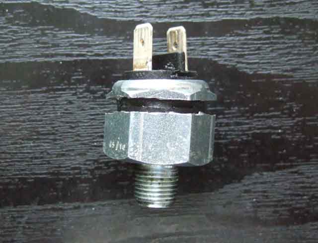 What lies inside the first replacement switch. I cut this one open (a bit more neatly than last time). No fluid on the contact side of the diaphragm, but a different internal construction to before. However the principle is similar i.e. fluid presses against a diaphragm, which presses against a metal disc, which pushes against a spring or springs. Where this one differs is that instead of the disc moving a contact finger to make the electrical contact, with a rubbing action, the disc bridges two fixed contacts directly. I.e. no rubbing action, and even though there is only slight burning on one part of the disc and one of the fixed contacts it is obviously enough to start affecting the quality of the connection.
September 2017: Andy Tilney posted on the MG Enthusiasts MGB Technical forum that he had found NOS Lucas brake light switches at LMS Lichfield who have tons of ex-MOD spares and other parts. However on external inspection they don't have the riveted spades like the originals, but have them going through the plastic moulding as on the poor copies. Rather dashed his initial euphoria, although when they checked their stock they found one with riveted spades, so he bought that one as well.
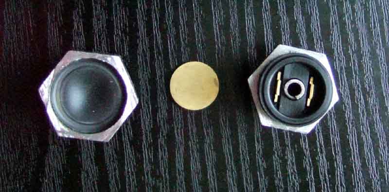 I went over and purchased one and sectioned it as before, with interesting results. Whilst basically operating on the same principle as the cheap copies i.e. a disc pressed against the internal parts of the spades, they do differ in detail and also probably in the materials used which may well be enough to make the difference. However their current price is the same as the usual suspects so I'd imagine the quality is the same. Coming in a green Lucas box counts for nothing, see this warning about indicator flasher units that have hazard flasher internals!. Only red/orange Lucas boxes - ideally saying 'Lucas' in full rather than the 'L' in a stripe - are truly NOS or OE.
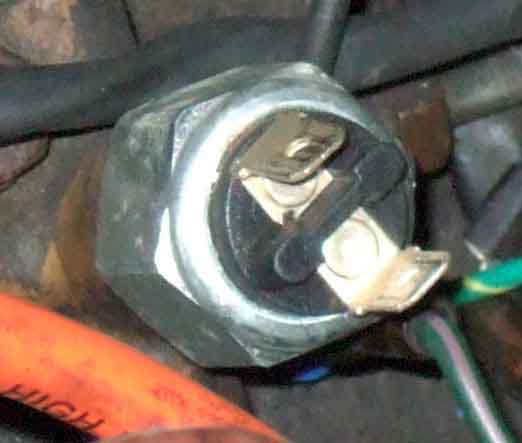 If the materials in these Lucas switch is harder that may well resist burning better, so I decided to test that theory. Couldn't find the earlier failure that I sectioned, so went to try the second one from the MGOC that has been in Bee for four years ... only to find it has riveted spades! And no, I'm not going to section that one as well!!
Relay:
Made to order
 If you can't get hold of an NOS switch then given the reputation of current-stock switches the only solution seems to be to fit a relay, so that the brake light switch only handles the very small current of the relay, it is the relay that switches the much higher current of the lights. See this modified schematic and information on how to obtain a ready-made relay or make your own up. Note that this relay should only be needed with the hydraulic brake light switch, not the mechanical switch mounted on the pedal box.
June 2011:
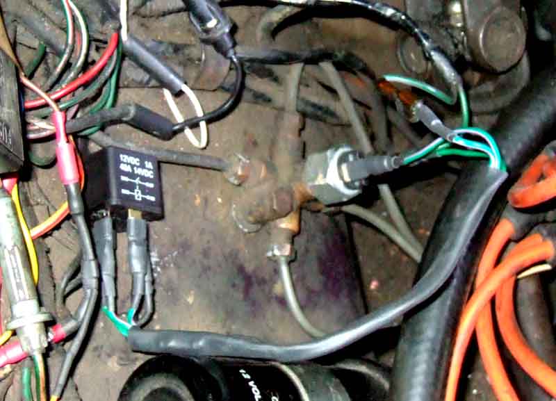 As mentioned above, just before a run I found the switch wouldn't light the lamps but would still operate a relay, so installed one as a quick-fix until I replace the switch. However given the reputation of current (ho ho) switches I decide to do a 'proper job' on installing a relay, so it can be used permanently i.e. with the new switch. Piggy-back a green off the hydraulic switch (rather than the purple, or a fused brown) to the relay terminal 30 (one of the contacts). Use a male to female extender for the green purple taken off the hydraulic switch to terminal 87 of the relay (the other contact). A female to female to connect the output side of the switch to one side of the relay winding (85), and take the other winding terminal (86) to earth. As it will almost certainly be used with a new switch, and as I don't know how the old switch will react to the back emf when releasing the relay, I fit a diode (A Lucas diode, no less!) between the two spades which go to the relay winding terminals to protect the brake light switch contacts. Note: This is now a varistor which means that positive earth cars with this relay can be converted to negative earth without changing the circuit. There is a very handy unused earthing point on the inner wing close to the hydraulic switch complete with screw and washer, for both mounting and earthing the relay, and I have brake lights again. The only issue is that with the dicky switch the relay is often giving a double-click when it operates and when it releases, which won't be doing the bulbs any good, so I'll be changing the switch sooner than later. Sooner, as it happened as just a couple of days later about to set out for the start I discovered that although the relay was still clicking it was clicking on at light pedal pressure and off again under normal braking! However I had a little-used switch under the dash wired into the engine compartment which reached the relay, so I had manual brake lights. Fortunately hardly had to use the switch until approaching the A42 for the journey home and in traffic, the Navigator was not best pleased when she asked why I kept reaching under the dash. Once on the A42 and M42 I didn't need them until the exit slip-road, and didn't need them travelling through Solihull to home. Next day I replaced the switch. I was intending to use the relay with the new switch from the start, but that would have told me nothing about the quality or otherwise of the new switch, and if they are poor quality then suppliers need to be made aware of it. So the relay has been left in-situ but not connected, and I will be checking the brake lights before and after each run for a while. Sure enough in a couple of years I was noticing from a tell-tale I had installed that the pedal was needing more and more pressure before the lights came on, so nagged MGOC until they replaced it, and connected the relay. No more problems, but five years later decided to add a mechanical switch so they come on as soon as the pedal starts to move.
Brake light relays made to order for the MGB as well as other makes and models.
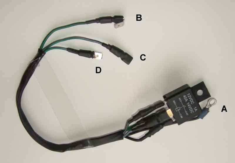 Uses existing connection points i.e. no cutting of wires, and can be restored to original in moments if required. Suitable for both positive and negative earth systems, just specify length of wiring from relay mounting point to switch position, and switch terminal type if they are other than conventional spades. Click the thumbnail for details.
Usually despatched within 24 hours of receipt of payment.
Uses existing connection points i.e. no cutting of wires, and can be restored to original in moments if required. Suitable for both positive and negative earth systems, just specify length of wiring from relay mounting point to switch position, and switch terminal type if they are other than conventional spades. Click the thumbnail for details.
Usually despatched within 24 hours of receipt of payment.
March 2021: If you find your brake pedal needs more and more pressure to light the brake lights then you will need to replace the hydraulic switch at the same time as you fit the relay. If you just fit a relay then the situation may improve, and the switch won't get any worse, but it is already damaged so must be replaced. Mike Robertson has just purchased one saying he replaced his switch about a year ago and it's got progressively worse so the switches obviously haven't got any better! He has another new one to fit with the relay.
However there is another option and that is to convert from a hydraulically operated switch to a mechanically operated.
Hydraulic to mechanical conversion - or 'seeing the light'. October 2018 Rubber bumper cars used a pedal-operated switch from the outset, which is standard practice on probably all cars these days. The main feature of these is that the brake lights come on as soon as you start moving the pedal, before there is any braking effect. For example it takes about 35mm of foot-pad movement before Bee's hydraulic switch turns on the lights, but only 7mm for Vee. Out of interest the ZS has 15mm but that switch has a much longer plunger. The MGB mechanical switches don't seem to suffer from the same problem that the replacement hydraulic switches do - I've not come across a single report of electrical failure of these, either original or replacement (however there have been some reports of plungers sticking on cars not used for a long time, and the insulated terminal plate on current stock popping out of the metal housing due to inadequate crimping). Why this should be I don't know as I haven't had the opportunity to open one up. They use the same 'soft-close' rather than 'snap-action' as the hydraulic switches, but maybe the physical design better allows for a wiping action such as the OE hydraulic switches had. There has been more chatter lately on various fora about the hydraulic switches, and people coming up with options to fit a pedal-operated switch to cars with the hydraulic switch, some using various bits of wood or drilling holes which doesn't appeal to me, but it spurred me on to see what I could do.
To fit the factory switch either needs you to replace the pedal cover - they are NLA but may be available from one of the breakers. Or you could modify the existing cover by drilling and welding a suitable boss or nut, but the positioning is fairly critical. Another option is to fit a switch in the cabin under the bulkhead shelf, resting against the front of the upper part of the pedal, and that is eminently feasible.
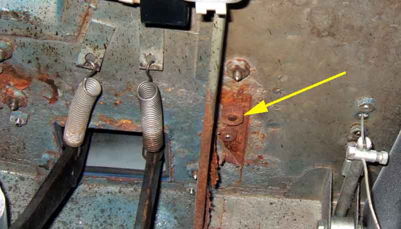 There is stiffener right beside the brake pedal, and a bracket for a switch could be attached directly to that. Not only would it be difficult to drill in that location, but I don't like drilling holes anyway. However there is a convenient welded nut for a pedal-box screw just the other side of the bracket, in a convenient position to mount a bracket, and that is what I opt to do. It just needs a longer screw, then a nut with washers to tighten the bracket against the welded nut. Oddly although this screw is one of six holding the pedal-box to the shelf it is a different size to the other five - 5/16" UNF as opposed to 1/4" UNF - possibly because it is the closest one to the brake pedal which has the greatest force applied to it during driving.
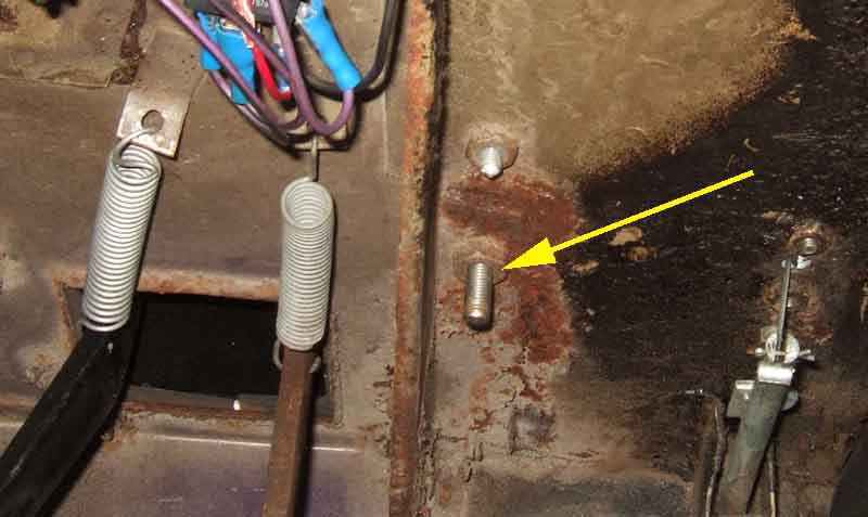 The standard screw is 5/8" long, replacing it with 1 1/4" allows a few threads to remain exposed after a plain washer, lock washer and standard nut have been fitted. You must use a plain washer even with a stiff- or Nyloc nut or as you tighten the nut it tends to move the bracket out of adjustment.
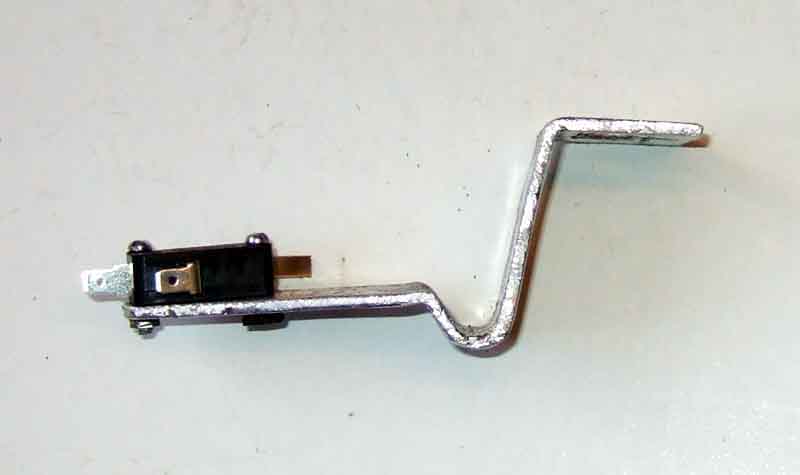 I chose to wrap the bracket round the flange at the bottom of the stiffener slightly to resist any attempt for the bracket to twist back from the pedal, which would compromise the adjustment and could leave the brake lights on. It does make for a tricky bending operation though, and if the part that goes across the pedal is too high it can foul the spring and make a noise as the pedal is operated and released. Subsequent thought is that a simple bend of 90 degrees under the stiffener would be more than adequate. For the second bend to make the part that bears against the welded nut, if this is slightly less than 90 degrees then as the nut is tightened it will tend to push the vertical part of the bracket firmly against the side of the stiffener to achieve the same positively located result, and be a lot easier to produce.
I used this switch from eBay. It's rated at 15A and 120v AC, and snap-action, so hopefully OK. Switches are rated higher on AC than DC as the alternating current passing through zero 100 times per second (50 Hz has one positive and one negative pulse per second, hence passing through zero twice for a full cycle) will tend to extinguish any arc created when the switch opens. However it's not the opening current that is the problem with hydraulic switches as that is only 3.5A and non-inductive, but the inrush current on closing which is a lot higher. But as these switches are snap-action and it is the 'slow-closing' of the hydraulic switches that causes the problem, we shall see. This switch has spade terminals to which standard spade females make a good firm connection. Note that the switch needs a normally-closed contact as the switch is released when the brake pedal is pushed, and mine has three terminals to give a normally-open (not used) as well as the normally closed. Switches with only two terminals may be of the normally-open type and not suitable for this application without additional components.
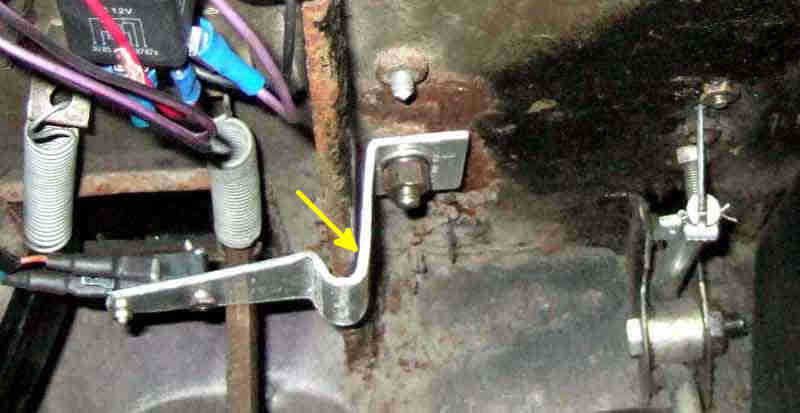 Bracket with switch and wiring fitted - pedal foot-pad travel down from 35mm to 8mm, and 5mm of that is taking up the free play in the linkage between pedal and master push-rod.
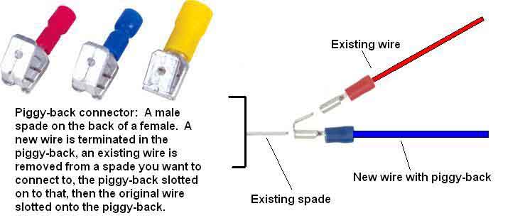 You have a couple of options for connecting the switch to the existing wiring - I fed 2-wire sheathed cable though the main harness grommet - and there is also the question of what to do about the existing hydraulic switch i.e. leave it connected as a 'second string' or take the wiring off that and extend it to the new switch. I decided on the latter option, and if you don't have a relay already fitted then the easiest way to attach the new wires is with piggy-back spade connectors, and it is completely reversible. However I already have a relay fitted using piggy-backs on the hydraulic switch and I want to retain that, as well as my tell-tale so I can continue to keep an eye on power going to the brake lights. I didn't want 'nested' piggy-backs i.e. one on top of the other, so I decided to utilise the bullet connectors which are close by where the main, rear and gearbox harnesses join together, and bullets on the new wires. You need a green wire to pick up the fused ignition supply for one side of the switch, as well as the green/purple going to the brake lights from the other side of the switch. The latter is easy as by substituting a 4-way bullet connector for the existing 2-way between the main and rear harnesses you can connect to the green/purple. And the green wire is just as easy as there is one of those going from the main harness to the gearbox harness on all MGBs from March/April 1967 for the reversing light switch. If you don't have that then you will have to pick it up from the brake light switch.
Supplementary brake lights: June 2021
 Third brake lights have been around a long time and while relatively easy to install to a GT behind the hatch they need to be slim to avoid obstructing the rear-view mirror. However roadsters are another matter needing some protuberance above the panel behind the boot lid, unlike OEM convertibles where it can be fared in to some part of the structure. Also possible on an MGB of course, but not as a simple add-on. But an MGOC forum post gave a link to something that combined high-intensity red lights with the white reversing light, which was worth investigating.
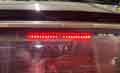 Easier on the GT as it can sit behind the glass, and 'ready-made' are more likely to be suitable.
 | Schematics: | Up to 1969 |
| 1970 and later |
Rheostat
Uprating
These are powered from the 'parking' or first position of the main lighting switch, and were never fused. Originally all cars had a rheostat between the speedo and the tach to progressively dim the lights including being able to turn them off altogether. Then North American MkII cars up to the 1970 model year had a simple on-off switch on the column shroud whilst other markets continued with the rheostat. In 1971 North American cars got the rheostat again and all cars continued with this until the end of production. This change for North America may have been due to lack of space on the first version of the padded dash. Until the 77 model year RHD cars always had the rheostat between the speedo and tach. LHD 'padded dash with glovebox' cars regained the rheostat on the right of the instruments between the choke and heater switch until the 77 model year. From 77 onwards RHD cars had it on the lower edge of the dash under the speedo. From 77 on LHD cars had the rheostat on the extreme left-hand side. 1977 and later models had the switches and heater controls illuminated at night as well as the instruments.
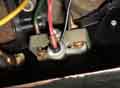 From the rheostat or switch to the gauge lamps the wire colour was always red/white, picking up an earth from the instrument case. On two-fuse fusebox cars the wire from the main lighting switch to the rheostat or on/off switch is red, on 4-fuse fusebox cars it is red/green. My V8 rheostat exhibits a smooth change in resistance from almost zero ohms at the 'bright' end increasing to about 10 ohms just short of the 'dim' end, then goes fully open-circuit for the last bit of travel to fully extinguish the lamps. The roadster has the 'off' section at the bright end. Both were faulty when the cars came to me, I remember paying top-whack for the roadster one, but gibbed at that when I had to replace the V8 one as well so bought a cheaper version off eBay, which probably explains the 'reverse' operation.
North American spec Mk2 prior to 1970 had the panel light on/off (not a dimmer) switch on the column cowl and those wires can get trapped causing short-circuits and damaged wiring and switches - none of the lighting wiring is fused at that point.
Bulb Holders:
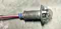 The original 4" speedo and tach use claw-type holders with a single wire for the 12v supply as they pick up an earth from the gauge body. The smaller 80mm speedo used on all V8s, and RHD RBs, and North American spec Mk2 (prior to 1977 at least) use a holder that pushes into a tube on the back of the gauge, and also only have one wire. The smaller fuel and dual gauges use the same tube-type fitting. My 73 and 75, and a 1980 that I rewired, all use MES E10 screw-fitting bulbs and holders. However a replacement harness for the 1980 came with T10 capless/wedge-type bulb holders. The problem with those in pre-77 gauges is that the bulbs can get dislodged and fall inside the gauge. The original tube-type holders for MES E10 bulbs don't seem to be available any more. T10 capless are available but have two terminals as the body is plastic and you have to make your own arrangements for earthing, as well as the problem of the bulbs falling in the gauges. A better alternative that is also available is the BA9 bayonet holder which picks up its earth from the tube the same as the original holder so only has a single terminal. These, and single-wire claw-type MES E10 holders are available from the likes of AES.
Rheostat/panel switch:
North American spec Mk2 to 1970 cars had a panel light switch on the steering column, the wiring can get trapped causing short-circuits and damaged wiring and switches. A dash-mounted rheostat was fitted to all other models.
Clausager writes: "Another innovation on the V8 model was the introduction of a new rheostat switch for the panel lights". Hardly an innovation as the rheostat was used on all models apart from North American spec Mk2 to 1970 which had a switch on the steering column. Whilst it may have been to a 'new' design it can hardly be called 'innovative'.
 The Parts Catalogue doesn't show a rheostat until BHA5047 for 361001 on i.e. the start of RB production but MGBs always had one. The knob isn't listed separately but suppliers have it as AHH5369 with a 'P' symbol. V8s are shown as having the same rheostat, again no knob, but it seems to have been 37H7995 with a speedometer symbol. Specified LHD markets such as North America, Sweden and Germany are showing as having the same rheostat (no knob listed) from 219001 for the 1971 model year, then BHA5198 from 294251 on for the 1973 model year changing to 37H7994 both with knob 37H7995. The September 76 catalogue shows RHD having rheostat AAU4944 and North America showing a manuscript amendment to 37H4994, no knob listed separately in either case.
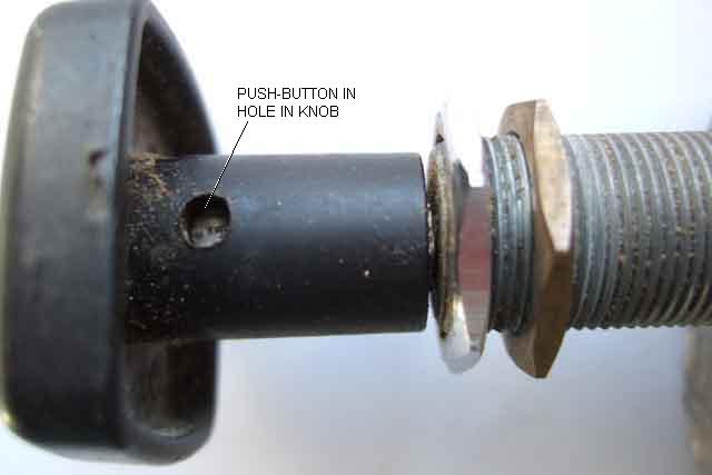
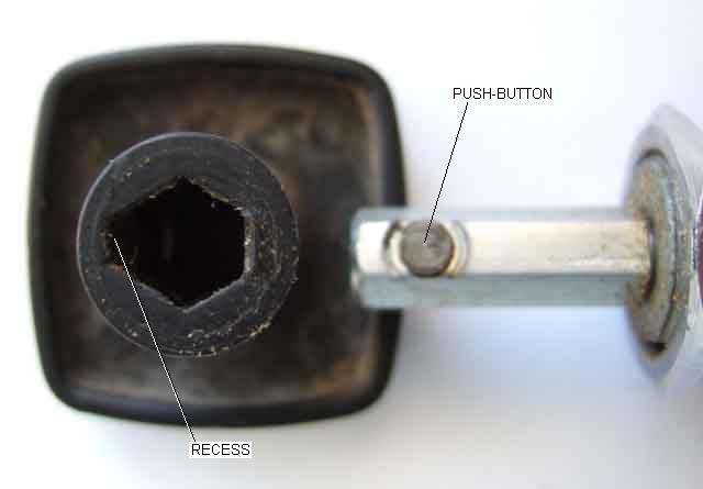 The rheostat knob is retained on the shaft by a push-button in the shaft which fits in a hole in the knob. The push-button must be depressed as the knob is withdrawn. The push-button is on a strong spring, and even when depressed the knob can be seized onto the shaft. The rheostat is usually retained in the dash by two nuts. The inner nut is to allow the threaded portion of the rheostat body only to protrude through the dash far enough to get the outer nut on for a neat appearance with no free threads showing. This picture shows a chrome nut, on the MGB it is usually a slotted ring which strictly needs a 'ring-driver' to remove and refit, but if used carefully long-nosed pliers or a screwdriver and light hammer used as a drift will suffice. When replacing the knob you should notice that one face of the hexagonal hole is spaced back more than the others, this must be placed over the push-button on the shaft, and depresses the push-button as you push the knob onto the shaft, until it clicks into place.
 On CB cars (except V8) there is a dashboard bracing panel behind the rheostat and between the main dials which means one of the main dials has to be taken out first in order to remove, or even access the terminals, of the rheostat. V8s and RB cars don't have that bracing panel and the main dials are smaller so the rheostat can be reached from behind more easily. Maybe tricky to juggle connections while fitted, but it's relatively easy to remove the knob, locking ring and wavy washer and pull the rheostat back and down for better access.
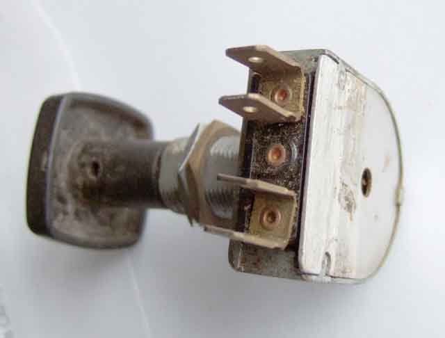
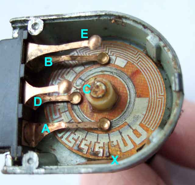 All the rheostats I've had (several cars) have been of the printed circuit variety where the changing resistance is obtained by having printed circuit tracks of various thickness and length switched in and out as required. If all the instrument lights fail the rheostat is a likely cause. They are quite expensive for a) what they are and b) the use they are, even with uprated instrument lighting. Nevertheless I have always replaced mine as I hate things that don't work properly, and haven't had a subsequent failure, even on cars used as daily drivers with a lot of 'lights on' use particularly in the winter. As these lights are unfused it has occurred to me that maybe one of the lamps was shorted out at some time in each cars life, which would destroy a printed-circuit rheostat pretty-well instantly. Current supply of rheostats in the UK (for all years) seems to be 37H7994 or BHA4278 ("knobs not included ...") which are wire-wound so should not burn out as readily at typically Ł22 to Ł27 (October 2019, although some sources are higher), which is a lot cheaper than the Ł50-60 I was seeing just a couple of years ago. I jibbed at paying the higher price to replace Vee's from the usual suspects many years ago and got one elsewhere, but discovered it functions the other way round i.e. anti-clockwise for bright then off instead of how I remembered it before. No big deal, it's not something I ever use anyway, I just don't like things not to work.
If your panel lights are dimmer than you think they should be, or don't work at all, the first thing to do is try bypassing the rheostat to see what happens. Although the rheostat only has two connections (it is just a variable resistor) you will actually see four spades in a row. Each connection has two spades, bent into a 'U' shape and riveted to the body in the bottom of the 'U', and the two 'U's are side-by-side, with a bigger gap between the 'U's than between the two spades of one connection. All years of MGB have one red or red/green wire on the one connection leaving a spare spade. Some years only have one red/white on the other connection also leaving a spare spade, so it is a simple matter to move one wire from its connection to the spare spade of the other connection to bypass the rheostat. It doesn't matter which wire goes on which connection. Other years have two red/whites going to the rheostat, in some cases in one spade connector so you can bypass the rheostat in the same way, but it seems that some may have two separate wiring connectors which occupy both spades on the rheostat output connection, meaning you can't get both on the input connection (which would require three spades), but you can still transfer one of them over to bypass the rheostat for some of the lamps to see if that makes them brighter. If you want to bypass the rheostat permanently for all lamps on these cars then you will need a Y-connector like these. You could use a Scotchlok but it would mean cutting the connector off one of the wires and they aren't the most reliable of devices.
If you have changed the instrument and control bulbs from the original filament-type to LEDs, the rheostat will no longer work as originally, as described here.
That leaves us with the normal situation of dim lights when everything is working as it should! It has often been said that the provision of a rheostat must have been a joke by someone in the factory, as with the best will in the world they are never going to be too bright with the standard bulbs. Filament bulbs do blacken on the inside as they age, failure seems very rare so most of them are probably very old, and replacement might help. Cleaning the inside of the cans and the back of the glass can help, as can repainting the inside of the cans with gloss white or silver, but is a bit of a fiddle and you could end up damaging the instrument. But is it even an issue, I ask myself? The beauty of analogue instruments is that you don't have to read the numbers anyway when you are familiar with the gauges, just be able to see the angle of the pointer. You don't read the numbers when you look at a clock or watch do you? You just look at the angle of the hands, and how many watches and clocks these days have numbers on them anyway? Over several years I tried a number of options, and whilst some were better than others, none were really worth the effort and/or cost.
February 2013:
But as time goes by and the years mount (mine), as well driving other cars and infrequent driving of either of the MGBs at night blunting familiarity with what the needle angles mean in particular the relationship between speedo needle angle and speed, improved brightness is probably becoming more necessary. Whilst investigating DRLs I had come across a 5-element LED which was worth trying in the gauges. It had a T10/wedge fitting for the rubber bumper pilot light in the headlights so not a direct replacement in the instruments on either car. But I had a wedge holder lying around and tried just holding it in position for the chrome bumper speedo and tach and it gave by far the best improvement of anything I had tried before. This is almost certainly due to the four radial elements being inside the case as well as the one forward facing. At the time I couldn't find any bulbs of this type with an MES (medium Edison screw, which is what all eight of my instrument bulbs are) fitting, but did find some bayonet types, so fiddled about quite a bit with wedge and bayonet holders and ended up with the speedo and tach on both cars much improved.
The ancillary gauges (and the smaller V8 and rubber bumper tach and speedo) have 12mm tubes on the backs for cylindrical bulb holders. Two of the previously obtained screw-in LEDs worked well in the dual gauge, but in the fuel gauge whilst they changed the hue to a blue/white the same as the other gauges they were not really any brighter, and even these new 5-element bulbs (wedge and bayonet) held in place seemed no better. This is largely because the fuel gauge has a completely different light path to the other gauges.
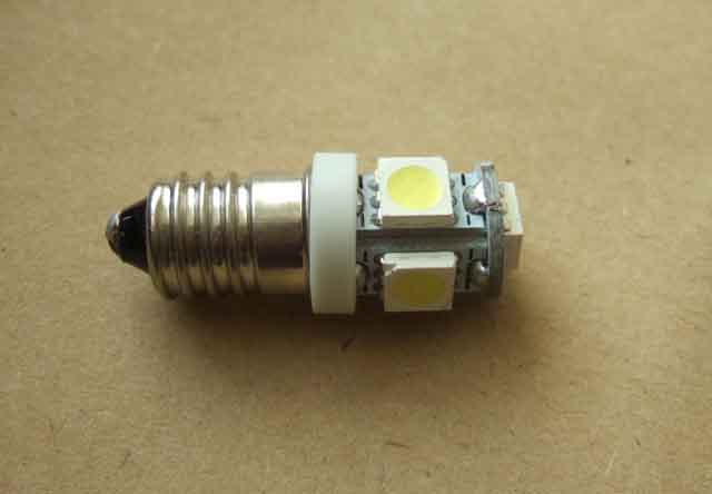 I was convinced there must be an MES i.e. standard screw fitting version of these bulbs, so kept looking from time to time. And while Googling '12v MES LED' I realised that an alternative description for the fitting was 'E10'. Googling that instead of MES got a couple of hits for the correct type of bulb, but it was factories touting for bulk purchases and wholesalers with bundles of 100 units. But then I noticed they all had the same description 'E10 5 5050 SMD LED' and Googling that led me to a pair for Ł2 and free shipping from China! A pal ordered a set, supposedly delivery in 30 days, but they actually took more like six weeks, with no response to emails, and while we were waiting there was a flurry of bad feedback complaining of non-delivery and no response to emails! Eventually they turned up after about six weeks. In the meantime I had found another source, also in China, just under Ł4 for a pair so nearly double the price but still very cheap. They only took a couple of weeks to arrive, so the extra cost is obviously to pay for a faster type of snail.
And trying those with the standard holders does give a noticeable improvement in the fuel gauge on both cars! So both cars now have four legible instruments.
I was convinced there must be an MES i.e. standard screw fitting version of these bulbs, so kept looking from time to time. And while Googling '12v MES LED' I realised that an alternative description for the fitting was 'E10'. Googling that instead of MES got a couple of hits for the correct type of bulb, but it was factories touting for bulk purchases and wholesalers with bundles of 100 units. But then I noticed they all had the same description 'E10 5 5050 SMD LED' and Googling that led me to a pair for Ł2 and free shipping from China! A pal ordered a set, supposedly delivery in 30 days, but they actually took more like six weeks, with no response to emails, and while we were waiting there was a flurry of bad feedback complaining of non-delivery and no response to emails! Eventually they turned up after about six weeks. In the meantime I had found another source, also in China, just under Ł4 for a pair so nearly double the price but still very cheap. They only took a couple of weeks to arrive, so the extra cost is obviously to pay for a faster type of snail.
And trying those with the standard holders does give a noticeable improvement in the fuel gauge on both cars! So both cars now have four legible instruments.
 The upshot is that these are a direct replacement for the standard filament bulbs and give a real improvement, so no fiddling around with alternative holders. And whilst they are a plug-in replacement for the 4" speedo and tach, the 80mm tach and the matching dual and fuel gauges, there may be a clearance issue with the 80mm speedo on the V8 and rubber bumper cars needing the holder to be spaced back a bit as I had to do with the BA9 versions. And I haven't tried these in any of the 77 and later plastic gauges. These have a green plastic bowl over the end of the standard bulb which will limit how far an alternative bulb will project into the instrument. It's also why you have to be careful with halogen bulbs, as being much hotter they can melt this green bowl.
October 2021:
 The fuel gauge has seen the least improvement, but then in an MGOC forum post someone posted a link to a 'flat faced' unit with eight small elements (E10 SMD 8 x 3020) all facing forwards instead of only one facing forwards and the rest distributed round the sides. That does give a small improvement to the fuel gauge to make it about the same as the dual gauge, and it also overcomes the problem of the 8 x 5050 fouling the speedo innards. The equivalent for the wedge-type bulbholders are T10 SMD 8 x 3020.
December 2021:
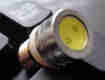 Finally (?) I spot an alternative COB type that are shorter than the 5 x 5050 and only slightly longer than a standard bulb and these prove to be slightly brighter than the flat-faced type. Not worth replacing that type, but definitely better than the 5 x 5050 type, and miles better than bulbs.
However with LEDs you will find the rheostat no longer works as it did. If you have all LED bulbs then really it won't dim them at all, if you have some filament bulbs left - i.e. in the cigar lighter or a clock or auxiliary instrument, then they will all dim slightly, the filament bulbs more than the LEDs. However the rheostat should still turn them off altogether as before. The lack of dimming is because the LEDs draw so little current, which means virtually no (no filament bulbs left) or very little (a couple of filament bulbs left) voltage is now being diverted to the rheostat so all or nearly all the voltage is still at the LEDs at the maximum dimming position. The 5 x 5050 SMDs take 30mA each (8 x 3020 35mA, first COB 60mA and 2nd COB 52mA) whereas the original 2.2w filament bulbs take almost 200mA each i.e. nearly six times the current. With an 8 ohm rheostat at full dimming there is only 7v left for four filament bulbs which are almost fully dimmed, whereas there is 11v for four LEDS, i.e. very nearly full voltage and very little dimming.
I know of a couple of cases where someone has gone to quite a bit of trouble to attach a conventional potentiometer of a higher resistance value to the back of the rheostat control to retain originality on the dashboard, but this isn't really necessary. By adding a load equivalent to the replaced filament lamps you will restore the function of the rheostat to a large extent. For example if you have replaced four 2.2w filament bulbs with 5050 SMD LEDs you need to generate 8.8w of load for the rheostat to work something like normally. 5050 SMDs take 30mA each or 1.5w for four, so you would need 7.3w of load from a parallel resistor, which at 12v represents 20 ohms. 8w minimum dissipation, 10W and 20w are available from the likes of RS Components and Farnell. However due to the different voltage/illumination characteristics of LEDs and filament the dimming may still not be exactly the same. A more sophisticated alternative would be to use the standard rheostat to control a transistor to give the required range of voltage output, and that is the next project.
Herb Adler has done a similar thing, see the appropriate section in this edition of his sagas.
1st April 2024: No - not April Foolery. Just come across these dimmable LEDs for instruments so you can use the standard dimmer - if you want. More expensive, and I've never felt the need to dim even the brighter LEDs. The dimmer does have an 'off' function which turns them off altogether, but I've needed to do that either, and in the early days when one failed in the dual oil/temp gauge in the V8 at the start of a long nght-time journey it made me feel very uncomfortable.
September 2020: While browsing the Classic Car LEDs website I came across the following statement:
A very common Classic Car owner question. Briefly, ours do with the old style internal variable resistor in the dimmer. This reduces the voltage available to the LED which in turn reduces the brightness. LEDs are far more sensitive than filament bulbs though which means a small change in the dimmer will have a bigger effect.
Fusing: October 2019
- Headlights and instrument/switch lighting were never fused from the factory.
- Factory or dealer-fitted optional front fog and spot lights or rear fog (1980) were never fused from the factory.
- The headlamp flasher circuit (optional and factory) was initially unfused and powered from the brown circuit, changing to the purple fused (always live) circuit for North American on Mk2 cars, but not until 1970 for other models.
- Brake lights and indicators were always from the green circuit in the fusebox until 1978, then from an auxiliary green circuit fed by an in-line fuse under the fusebox.
- Parking and number-plate lights were unfused on Mk1 cars, on Mk2 cars prior to 1970 with the two-fuse fusebox there were two in-line fuses by the fusebox one feeding the front and the other the rear, and from 1970-on there was a four-fuse fusebox with the top two fuses feeding the corners of the car, one for each side.
- The map light was always unfused off the parking light circuit.
- Factory-fitted reversing lights (March/April 67-on) were fused from the green fuse in the fusebox.
- Courtesy and boot/load space lights - optional and factory for Mk2-on - were always powered from the purple fused circuit.
- North American side-marker lights powered from the headlight circuit prior to the seat-belt warning system fitted during 1972 were unfused. After that when powered from the parking light circuit they were fused with the parking lights.
Particularly when fitting relays to the headlight circuit consideration should be given to adding fuses as the greater current that relays will allow to flow will cause more damage and faster. It is advisable to add one fuse per filament if you are not to be plunged completely into darkness from a fault at one headlight, more information here.
Parking light circuits on Mk1 cars can be fused as per early Mk2 cars i.e. one fuse for the front and another for the rear, inserted where the two red wires in the main harness (12v supply and feed to front lights) and the red in the rear harness come together. Part the three wires and determine which from the main harness carries 12v with the lights turned on, and connect that to a 4-way bullet connector. Connect two in-line fuses to the other side of that, one going to the other main harness wire via a 2-way bullet connector, and the other going to the rear harness via another 2-way bullet connector.
Instrument/switch lighting circuits have been known to cause wiring damage, and on every car that has come to me with rheostat lighting the rheostat has been burnt out, possibly from previous shorts by the instruments, and fusing these depends on the year of the car. To add a fuse ideally it should be as close to the main lighting switch as possible, where the red (prior to 1970) or red/green (1970 and later) wires have two branches one to the parking lights and the other to the instruments. On 1977 and later this will be where the lighting switch sub-harness plugs into the main harness with a multi-way plug. However this does mean guessing which one of the two wires to cut, and you have a 50% chance of getting it wrong.
On Mk1 cars the parking lights weren't fused either, so an in-line fuse with a female spade one side and a male the other between the two red wires and the lighting switch will protect all of them ... with the proviso that a fault at the instruments will extinguish all the rear lights. Mk2 cars prior to 1970 still had the two-fuse fusebox, but had two in-lines in the parking light circuits one feeding the rear (which again would extinguish all lights at the rear if it blew) and the other the front, where at least you have headlights.
The alternative is to insert it in the red/green at the rheostat using an in-line fuse with a female spade one side and a male the other, but even that is complicated prior to 1971 because as well as the red/green feed at the rheostat there is a second wire daisy-chained on to the map light. In that case inserting an in-line between the two red/greens and the rheostat would protect the instrument lights, but not the map light.
Factory/dealer/PO-fitted fog and spot lights should be easy to fuse where the switch supplies are picked up from existing parking and headlight circuits.
For unfused headlamp flasher circuits it should be possible to add an in-line fuse at a bullet connector behind the dash where the tail from the indicator/flasher switch connects to the main harness. However the diagram for 62 to 64 cars shows the brown wire going all the way back to the fusebox. If this is a single wire in a spade connector it can simply by moved to the other end of the same fuse i.e. the purple circuit to fuse it.
For North American side marker lights powered from the headlights there are three blue wires joined together by the fusebox - two from the main harness one of which is the 12v supply the other going to the front markers, and one to the rear harness for the rear markers. Identifying which of the two blues from the main harness is the supply, and inserting an in-line between that and the other two blue wires will protect both front and rear marker lights.
The factory-fitted rear fog light circuit almost certainly uses multi-way plugs and sockets to connect the manual switch to the headlamp circuit i.e. no bullets or spades, so a blue wire would have to be cut to insert a fuse. As there are two blue wires at the main lighting switch and you have a 50% chance of getting it wrong, it makes more sense to cut the single blue at the manual switch.
Seat-belt and Brake Warning Lights:
Switch Illumination: June 2013
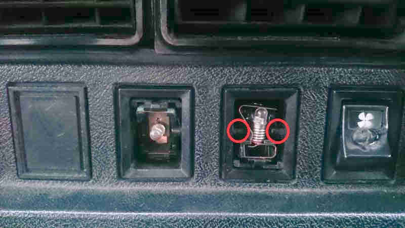 For the 77 model year on the factory supplied night-time illumination in the switches (and in some case a tell-tale function) and heater controls from an internal bulb in each, but on earlier cars you have to grope in the dark to some extent.
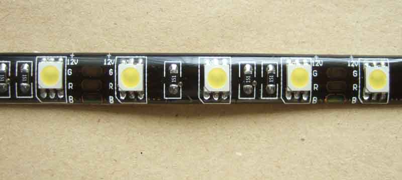 About the same time Michael and I were fiddling with the instrument lighting we had the idea of using LED strip to illuminate the dash, particularly the switches. 77 and later MGB have illuminated switches and heater controls so are already catered for. Available in a variety of colours, we decided to be relatively sober and act our age choosing warm white over other offerings such as blue, green, red and yellow.
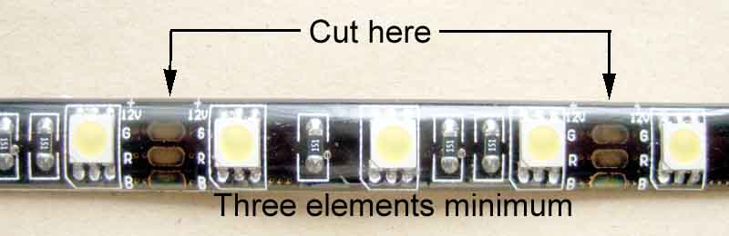 The strips can be cut to the required number of LED elements, where there are typically four short copper strips between each group of three LED elements, three elements being the minimum that can be powered off 12v without an external resistor (but see below). Unless you are going to daisy-chain two or more strips, cut to the end of the strips rather than in the middle, and that gives you more copper strip to make a connection at one end, and none at the other.
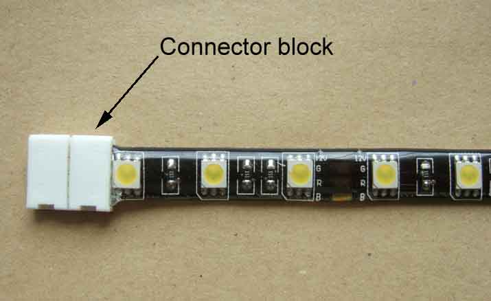 There are connector blocks available but they are relatively big, the type to connect two strips are relatively cheap but the end ones with wires are four times the price. You can use the first type with wires, inserting the strip into one half and the wires into the other, but it's just as easy and makes a perfectly good connection by soldering direct to the copper strips, then using heat-shrink to cover the connections, and a blob of silicone sealant in the open end to stabilise the wires. The copper strips are very close to one of the elements so it's preferable to use enough heat-sink to cover the nearest one and so get a stronger joint.
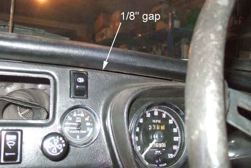 Mounting them under the dash crash pad makes them unobtrusive if not invisible from the driving seat, and the wires can be fed through the gap between the top of the dash proper and the dash top under the crash rail. Depending on how the dash and crash pad have been fitted there will either be a clearly visible gap to feed the wires through, or you may need to wiggle a small screwdriver through to open this up.
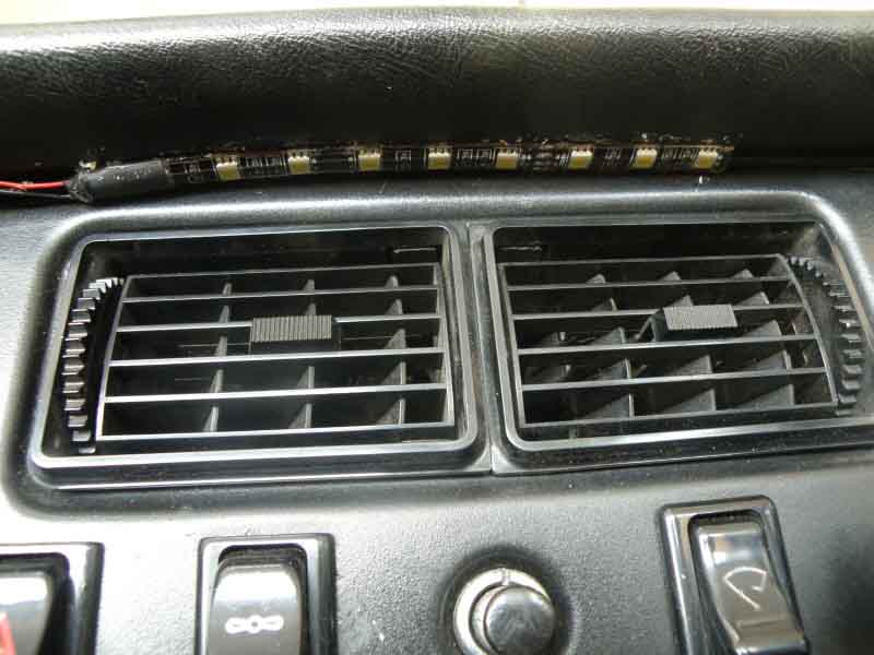 Although the LED strips are self-adhesive and have a peel-off strip the textured surface of the crash pad will limit its effectiveness so you will probably need to use an additional adhesive, such as Copydex, or silicone sealant.
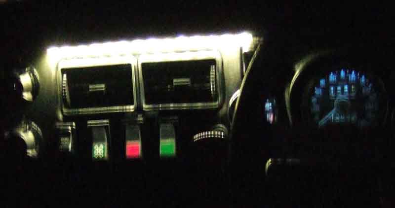 The LED elements are quite bright and so you may need to use a series resistor to bring this down to an acceptable level.
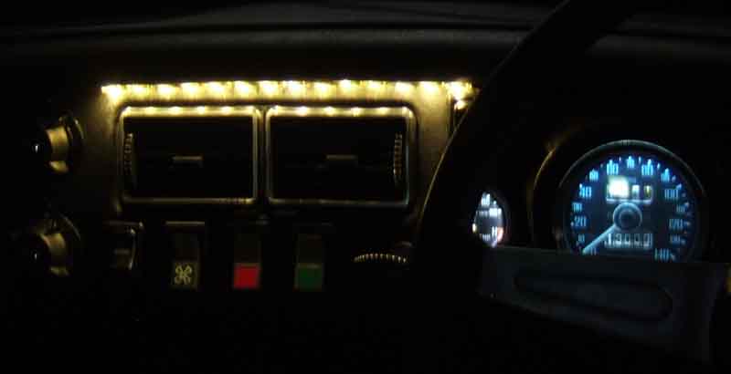 Michael used 330 ohms in series with nine (one concealed) 5050 elements, I used 1.5k although anything from 1k to 1.5k gave very similar results. Herb Adler used 1.8k ohms in series with six although I don't know whether his are 5050 elements or not. Each group of three are effectively in parallel with all the other groups of three across the voltage supply, so the more groups of three you use the more current they will draw. This means theoretically the resistor to achieve a given brightness will vary according to how many groups of three you have used, i.e. a lower value for more groups, but in practice they take such a small current that choice of resistor is going to be down to personal preference of resultant brightness rather than how long the strip is. A resistor, if fitted at the end of the wire where it joins the white/red instrument lighting feed elsewhere, also means that the current will always be at a safe value even if the wiring or LED strip should happen to short out. For example even 330 ohms will limit the current to 42 milli-amps, whereas a single 2.2w instrument bulb takes 160mA.
A shorter strip can be fitted below the dash to illuminate the centre console. Join the wires from the two strips together, via a single resistor, to the instrument lighting feed.
Uprating
Reversing lights with auxiliary brake light function
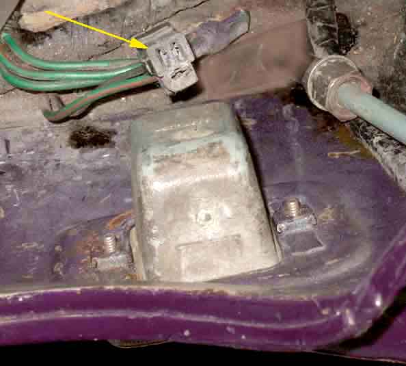 Factory equipment from April/May 1967, may have been a factory fitted option before then. The lens screws through the body of the light unit into captive nuts behind the rear panel, and unusually there is a 2-'pin' plug on the harness that connects to two small spades under the light unit. The bulb is a festoon-type GLB270 (18W, North America) or GLB273 (21W, elsewhere) although these days some describe the GLB270 as '18/21W'. There are several different lengths of festoon and these are 44mm. The lens (37H1760 with gasket 37H1759 and two screws 37H3751) seems to have a silvered coating on the back round the edge as a pseudo chrome bezel. The light unit complete with lens is BHA5167 and also uses gasket 37H1759 to the body.
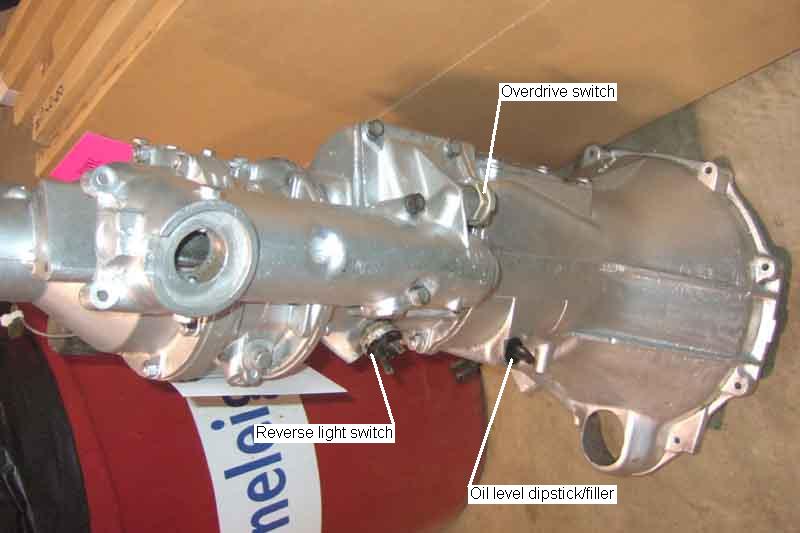 The reverse light switch is screwed into the upper half of the gearbox and can be seen on the right-hand side looking directly up into the narrower part of the tunnel. Access to this switch is not easy, but disconnecting the rear cross-member at the chassis rails allows the gearbox to swing down a little for better access. You can also remove the centre arm-rest/cubby (where fitted) and pull back the tunnel carpet for some access from above. On 3-synch cars there is a large access panel on top of the tunnel that can be removed, but even on 4-synch cars there is a small panel in front of the gear lever which can help. Note that OD gearboxes prior to September 66 may not have provision for a switch, unlike early non-OD gearboxes.
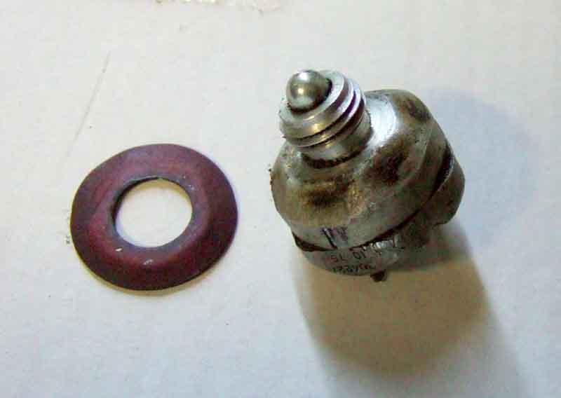 The only 'adjustment' on these switches is provided by spacers, and a loose or worn switch can prevent the light coming on or make it erratic. In the case of wear causing non or erratic operation removing a spacer may be all that is required. OTOH a missing spacer can cause it to be on when it shouldn't be. It's always been said that these spacers are fibre, and there were originally two of them. However on Vee the OD switch spacer is copper and the Parts Catalogue only shows one per switch. Various suppliers only indicate one (1B 3664), and fibre, but Brown & Gammons shows a fibre washer for the reverse switch and a copper for the OD (3H 550), which is the same as for the brake banjo! Incidentally the OD and reverse light switches are the same part number. Vee's reverse light switch has one thin fibre spacer so exactly as per Brown & Gammons, and this is noticeably thinner than the OD copper spacer.
Automatic Gearbox:
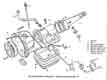 The automatic gearbox uses a completely different switch that combines the reversing lights and inhibitor functions. It screws into the side of the gearbox and there is a calibration process to ensure it is screwed in to the correct position.
Map Light:
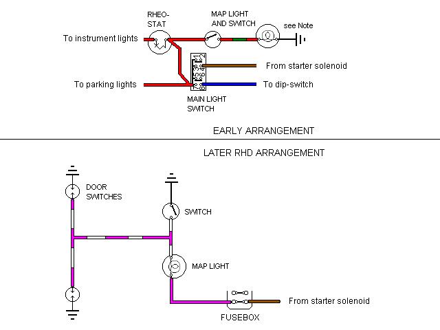 Originally the MGB had a map light for the passenger, controlled by an on/off switch close by when the main lighting switch was in either of its 'on' positions. On Mk2 North American cars the map light moved to a centre console, replaced by a courtesy light in 1971. For 1971 only non-North American cars had the map light available at any time with the on/off switch, as well as being lit from both driver and passenger door switches, in 1972 it was replaced by a central courtesy light. Map lights were never fused.
This light (when fitted to the dash i.e. excluding North American centrally mounted lights) is a little confusing as many parts sources indicate it is the same as the number plate light that attaches to the overrider, but this is only partly the case: It uses the chrome cover (37H5426), glass dome (606078) and seal (17H5302, this should be a round seal but some suppliers have it as a diamond-shaped seal which can be cut down) from the number plate light. However it doesn't use the bulb holder, and it is a little cheaper to get the individual parts. For the bulb holder it uses a claw-type holder with a 2.2w bulb the same type as for the speedo and tach. Well I say the same type, and whilst the UK diagrams do show what would appear to be a one-wire bulb holder which picks up an earth from being clipped into the dash (confirmed by Bob Gibbons with his 1964 LHD), a replacement harness has a red/green and a black wire going to a 2-wire claw-type bulb holder, so has a wired earth. This is preferable as a freshly painted dash may not supply a decent earth without scraping some of your precious paint off, but does not appear to be listed separately in the Parts Catalogue. Indeed it doesn't appear to be listed by any of the usual suspects, although I did find a 2-wire claw-type holder listed under part number AEU1313 from a number of non-MG sources. North American spec schematics for Mk2 cars do show a wired earth.
The red/green from the bulb holder goes into the harness and back out again with a red wire from the main lighting switch. These wires have spades on a replacement harness (as does Bob Gibbons' 1964 LHD), but current stock from UK suppliers shows the switch as having screw terminals.
Courtesy Light:
From the Leyland circuit diagrams North American Mk2 cars seem to have had a central console with a map light controlled by a separate rocker switch, and an optional courtesy light with a manual switch as well as being operated by both doors. However Clausager indicates they had the map light until 1970, then from 1971 the courtesy light. The following year i.e. 1972 non-North American cars had the map light replaced by a central courtesy light, lit from an integral manual switch as well as from driver and passenger door switches at any time. But again the Leyland circuit diagrams are confusing in that they show an optional interior light controlled by two door switches in addition to the map light, from 1968 to 1970. Again Clausager indicates a simple change from one to the other for the 1972 model year, when non-North American cars gained the centre console.
Note: Haynes issue dated 2010 with coloured schematics has an error in the drawing of the courtesy light for 1973 cars, and later. As shown it wouldn't work at all from either the door switches or the manual switch, but if both are operated at the same it will blow the purple circuit fuse. Earlier versions e.g. my 1989 copy are drawn correctly.
 Getting to the bullet connectors behind the console for the courtesy light, lighter socket etc. is a real pain as there is not enough slack in the harness, so I made an extender.
October 2017: Since getting Vee back on the road I'd noticed that unless the passenger door was fully shut the courtesy light wouldn't go off. I didn't do anything about it as if anything it acted as a safety feature warning that the door wasn't fully shut, like modern cars where the switch is on the B-post. But I wasn't totally happy with the alignment of the passenger door, so slackened the door to hinge screws, lifted the door very slightly and retightened. That put the door right, but also means the light now goes off when the door is only half latched, as it always used to before. I mentioned this in connection with an MGOC thread on door hinges, and John Holland said he had to add a packing piece before his would go off at all. Given the amount of travel of the switch plunger after the contacts open I'm amazed they are so marginal.
LED upgrade:
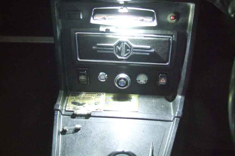 On a trip away I must have caught Vee's load-space light switch and knocked it on when getting bags out, but wasn't made aware of it until some 30 hours later. Fortunately she still started, but it got me thinking about LED replacements for the interior lights in case it happened again, as well as for their increased brightness. LED replacements for the GLB254 6w festoon are commonly available, but I came across two types. The one with three 5050 SMD elements and a resistor seem to be the most common at around Ł2.50, but I also found one with two tiny elements and additional electronics, and an alloy heat-sink at Ł1.50. Now one would expect the first type to be better, but I was intrigued enough (and the cost was low enough) to buy one of each.
Testing them the Cree-type was obviously much brighter, but how to compare them in a photograph without a lot of fiddling around with wires and holders? I put them in the reversing lights! One thing to note is that the 3-element type are polarity sensitive so if they don't work one way round try them the other. The other type are not polarity sensitive so work either way round. The 5050-type are really not much brighter that the originals, only whiter, which seems to be the case for stop/tail LEDs at least. It will be good enough for the V8 load space, and I'll use the Cree-type for the interior light. The supplier had one remaining Cree-type so I ordered that as well for Bee's interior light. She already has an 'eagle-eye' LED boot light which is a great improvement over the standard light.
The Cree-type are so bright that I was tempted to buy more for the reversing lights. The supplier had no more, and whilst they are available elsewhere they are typically Ł6 each or two for Ł8, or I could settle for the less bright type. But there is also the issue of legality and acceptability to insurance companies, and having read of someone with LED number plate lights having an insurance claim refused I decided to leave them as they are.
That leaves the current drawn by each type:
- The original 6W festoon takes 350mA
- The 5050-type LED takes 28mA
- The Cree-type LED takes 225mA
- And out of interest the single Eagle Eye in Bee's boot takes 50mA
I've used 'Eagle Eye' LEDs for DRLs and they are very effective. I've also used one in a trial of a vastly improved boot light, and it occurs to me that they could be used as 'puddle lights' when mounted in the bottom of the door, and red versions as rear-facing marker lights as the doors are opened. However these last two would require the drilling of holes in the door case.
Door switches Added October 2011:
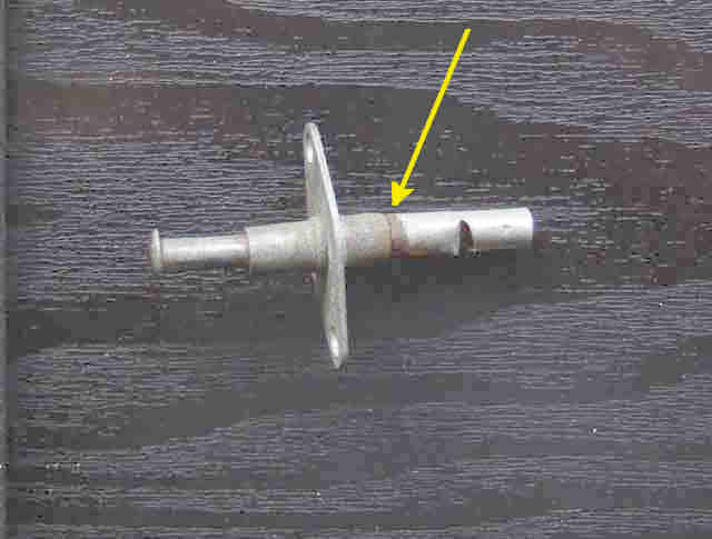 BL door switches (always BHA4593 for the courtesy light) were always subject to water ingress and corrosion as they are effectively outside the cabin, giving flickering of the courtesy light or failing to operate at all. Two of mine were like that so I replaced them, but at the time the original style were not available and the replacements were not only different in appearance but also needed the hole in the A-post opening up a little bit. By 2012 Brown & Gammons and others have the correct switches (albeit with complaints of the plunger buckling), but dodgy switches may be recoverable, particularly if they are only intermittent and not so badly corroded they don't work at all or have crumbled away, click on the thumbnail. This should only be a problem for the main doors, the roadster boot lid and GT hatch seals should be protecting those switches completely.
Note that North American spec cars from 1970 had a 'key in, door open' warning buzzer that involved a second switch BHA4984 on the driver's door. This switch has two wires and both contacts are insulated from the body i.e. is totally different to the courtesy light switch, so problems and possible fixes are probably different as well.
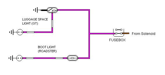 Both UK and North American roadsters had a boot light (BHA5040) from the 1971 model year onwards, fused from the purple circuit, operated by a switch (13H391) activated by opening the boot lid. These switches are inside the boot so protected from weather.
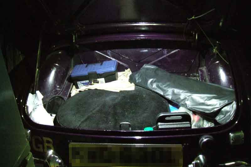 However whilst the light gives a reasonable light when there is not much in the boot, if it is fully loaded it gives virtually no light at all. A pal had the idea of using one of the 'Eagle Eye' LEDs I had used for the DRLs, and it works very well. Tucked up into the recess of the boot lid reinforcing frame where the latch release button is, but positioned to one side so it doesn't interfere with the mechanism in either the locked or the unlocked positions, it is at the perfect angle to illuminate the whole of the boot with a bright white light.
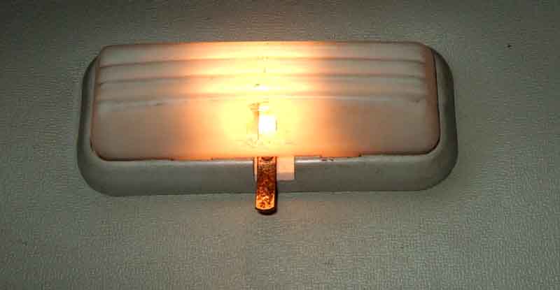 Both UK and North American GTs had a load-space light (EAM1651) from the 1971 model year onwards, fused from the purple circuit, with the switch (13H2018) operated by the hatch being opened as well as a manual switch, and again the switches are inside the cabin so protected from weather. Not sure why it needs a manual switch ... unless someone is sitting (never 'sat'!) in the back ... reading a magazine ... in the dark.
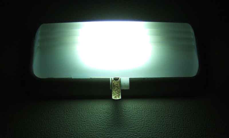 While updating the courtesy lights with LEDs I took the opportunity to do the same with the load space, and replace the melted cover.
North American side marker lights:
Factory-fitted:
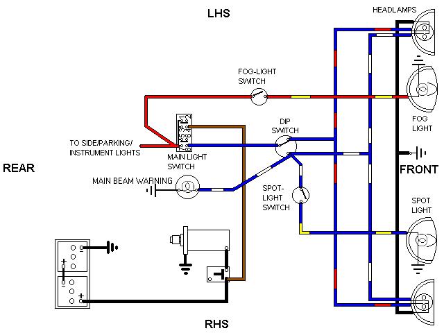 The optional factory-fitted front spot/driving lights were always wired to be available with the main beam if required.
From inception until 1970 optional factory-fitted front fog lights were wired, via a switch, to be available with the side lights if required. Factory or dealer wired fog and spot lights were powered from unfused circuits, but it should be easy to add fuses.
The optional factory-fitted front spot/driving lights were always wired to be available with the main beam if required.
From inception until 1970 optional factory-fitted front fog lights were wired, via a switch, to be available with the side lights if required. Factory or dealer wired fog and spot lights were powered from unfused circuits, but it should be easy to add fuses.
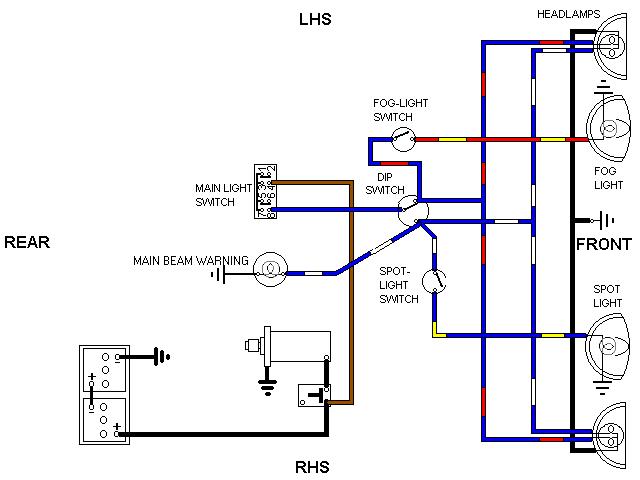 From the 1970 model year the front fog lights were wired to be available with the dipped beam if required, maybe a regulation change, but this renders them pretty useless as dipped beams throw back a lot of glare in fog. By the time my 2004 ZS was built regulations allowed front fogs to be available with the parking/position lights on only.
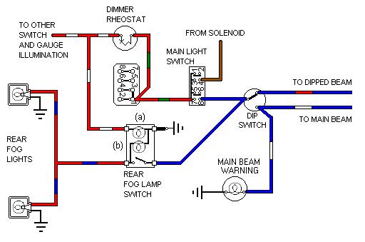 A pair of square Lucas rear fog lights were factory-fitted to all home-market cars for the 1980 model year, wired to be available when the headlights were on dipped or main beam. Again, if driving in thick fog with front fogs on without dipped headlights this means rear fogs wouldn't be available. This time my ZS is the same - if only the rears are turned on, but if one turns the front fogs on with parking lights then the rear fogs become available - sensible. However if you use drive-on wheel ramps these can catch on the ramps before the car has been raised high enough to clear them, they can also skid on concrete when trying to drive up them. Pre-ramps, or ramp extenders, solve both problems as described here. A similar problem occurs at the front with after-market valances such as the ST air-dam.
After-market:
You have a number of options as to how to wire them - available all the time; available when the side lights are on; or available when the appropriate headlights are on. In all cases except the first a relay should be employed to reduce the load of the extra lamps on existing wiring and switches to a minimum. All additional lamps should employ an in-line fuse, which if standard-gauge wiring, switches and relays are used, can be a standard 17-amp rated, 35-amp blow fuse. A lower-rated fuse could be used, but why complicate matters with a proliferation of fuses with different ratings? And if an auxiliary lamp fuse does blow it can be replaced with one of the spares from the main fuse block - once the fault has been cleared of course. I suggest that a single fuse for all lights is adequate except for night rallying when separate fusing of each front light, including each headlight filament, would be more robust.
Personally, I have my front and rear fog lights wired so that they are available when the side lights are on as I can't see much point in having front fog lights if you can't use them without being dazzled by the glare thrown back by normal dipped lights. The following schematic has all three types of lamp wired in this way:
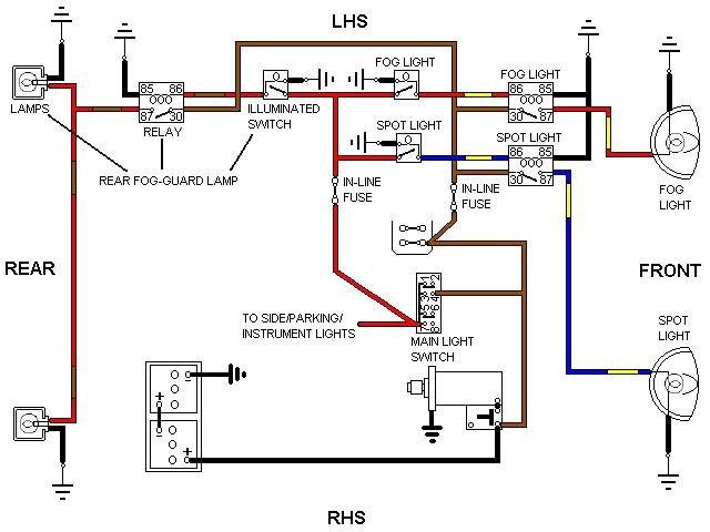 My 2004 ZS is wired this way from the factory, although I'm told by people from North America that this is illegal there and they can only be used with headlights. I have a vague recollection that the UK might have been the same some time ago, if so common sense has obviously prevailed since then. The MOT requirement is: "Front and rear fog lamps are permitted to operate independently of any other lamps or ignition systems." (MOT Manual Section 4.5.1). A 'tell-tale' indicator is required but only for mandatory rear fog lights i.e. on vehicles first used after 1980. At one time the manual said it could just be a coloured tag visible when the switch is operated as well as a light, but now it mentions neither (MOT Manual Section 4.9). I.e. it could be either, but it will only be checked for mandatory lights which from the factory did have a light.
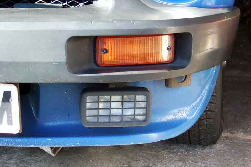 Rectangular fog (kerb-side) and spot lights as fitted to my V8. However as the glass on the spot got broken many years ago, and I haven't needed to use the fog light for even longer, after the restoration in 2017 I didn't bother refitting them.
People sometimes suggest using the off-side reversing light as a rear fog light with either a red LED or red lens fitted. The Road Vehicles Lighting Regulations 1989 Schedule 11 2.(d) says that optional rear fog lamps must have a minimum separation distance of 100mm between a rear fog lamp and a stop lamp. On an MGB there is only 45mm between the illuminated reversing light and stop/tail lenses at their closest point which appears to preclude that. But Dave Birkby wrote on the MGOC MGB Technical Forum in April 2019:
Front or rear fog lights can only be used in poor visibility e.g. fog, falling snow or heavy spray. If someone is travelling behind you in convoy, turn your rear fogs off, so they can better see your brake lights and not be dazzled. Never use them as a matter of course at night, particularly in built-up areas in the rain, the resulting dazzle for following drivers even travelling at a safe distance behind you severely limits their ability to see anything other than your fog lights - including your own stop-lights. In the UK it is an offence (Highway Code Rule 236) to use fog or spot lights inappropriately, you risk a Ł1000 fine - per light! Day-time running lights are different - they should come on when the engine is started, but must go off (or be dimmed) as soon as sidelights or headlights are turned on.
Auxiliary switches:
 Fitted where you will, but on the V8 a PO had butchered the dash panel below the air vents to fit a mish-mash of switches for cooling fan override, front fogs, and maybe something else, which looked a mess. I was fortunate to get a set of three illuminated rockers comprising one with a fan symbol (which shows me when the thermo switch has come on as well as being able to turn the fans on manually), a red one (rear fogs) and a green one (front fogs) at Stoneleigh one year. Slightly bigger than standard, but with a fascia cover-panel cut from a piece of textured black plastic they cover the bodging pretty well. These illuminated switches have probably every logo variation you are likely to need, and whilst they are a more modern design of rocker they are said to be the same size as the MGB pre-77 rockers.
Number Plate lights: April 2009
 Number plate illumination lamps were originally mounted on the rear bumper overriders (amazingly front overriders on UK cars were optional to begin with!). For the 1970 model year North American cars had two 'quarter' bumpers instead of a full-width and the lights were tucked inside the ends of these. They moved to the bumper itself for 1974 non-North American cars, to the number-plate backing-plate for North American 1974 model year cars with the 'Sabrina' overriders, and for all rubber-bumper models. When mounted on the backing-plate they had 12v and earth wires, but for the overrider and bumper-mounted types there is only a single wire to provide 12v for illumination and a very tortuous path for the earth return relying on the physical contacts between bulb, bulb holder, light unit, light unit plinth, overrider and overrider bolt (or bumper), bumper irons and body plus various nuts, screws, washers and bolts! Mine didn't work after restoration so I provided an earth wire from the light units back to one of the existing earth wires. lights.
 It was only when I received an email from Felix Weschitz in Austria saying he had the same problem, and couldn't find my own well-hidden comment on the problem, that I decided to add this specific paragraph, and a link to Felix's information. Reversing lights have an earth but that goes directly back to a number plate bolt on RHD cars so you will still have to do as Felix did, but cars for North America with side markers use bullet connectors for both those and the reversing lights so you can tap into those. Number plate lights mounted on the number plate backing plate (North American split bumper and all rubber bumper) were provided with earth wires from the factory.
May 2017: Neil Harrison on the MGOC forum raised this problem, and a couple of us suggested the earthing. I mentioned I had run an earth wire in from a light-unit stud where it is inside the overrider. However he tried that, and it made no difference. So he dismantled the light unit and found it had been assembled such that the rubber gasket was completely insulating the bulb holder from the remainder of the fitting. Assembled correctly it worked and didn't need the earth wire. So if you have the same problem before going to the trouble of making up and installing an earth wire, clip a temporary earth to the light-unit stud inside the overrider, and see if that makes it work. If it does, then it does need an earth wire.
Sheared stud repair: October 2016 When removing the light units from Vee's number-plate backing as part of her restoration I was annoyed to shear a stud on one of the units as otherwise they are both in as-new condition. Looking at the studs they have a shallow round head, then a short square shank, which is pressed into a square hole in the base-plate. "I can make one of those", I thought.
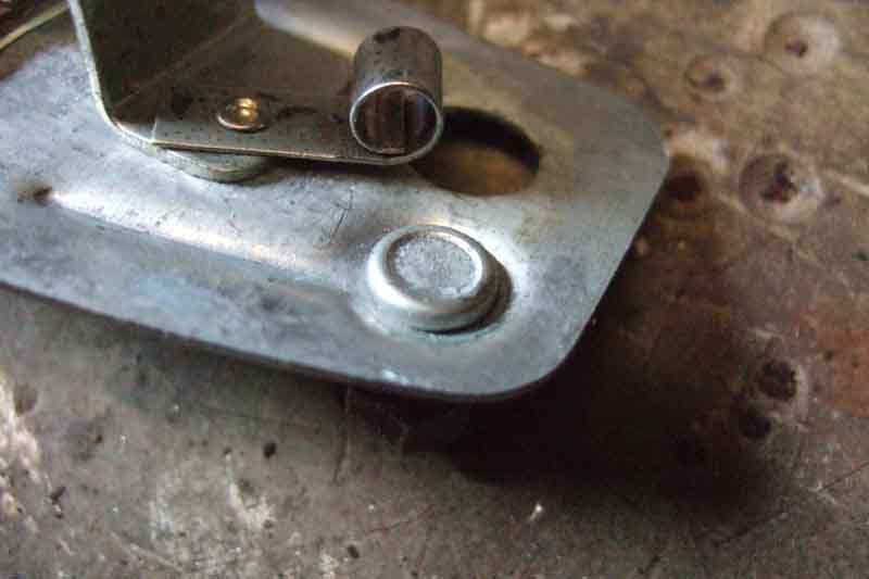 I pressed out the sheared stud in a vice using a socket over the head. I found a cheese-head screw that fitted the other nut, and a nut that fitted the screw. I then filed the lower half of the head down into a square using a needle file. On the base-plate I used the square tang of a file in the square hole to bow it downwards a little, opening it out so the screw just fitted. Then using the 1/4" drive end of a socket, which just fitted over the square shank on the new 'stud', and a vice, pressed the base-plate round the screw flat again, so reducing the size of the hole, and pinching-up the screw. About an hour's work, and Ł20 saved.