


September 2016 - November 2017
October November December January 2017 February March April May June July August September November
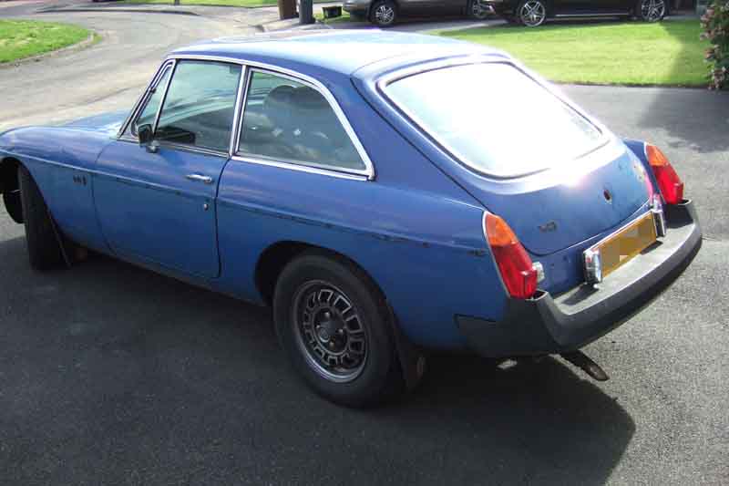
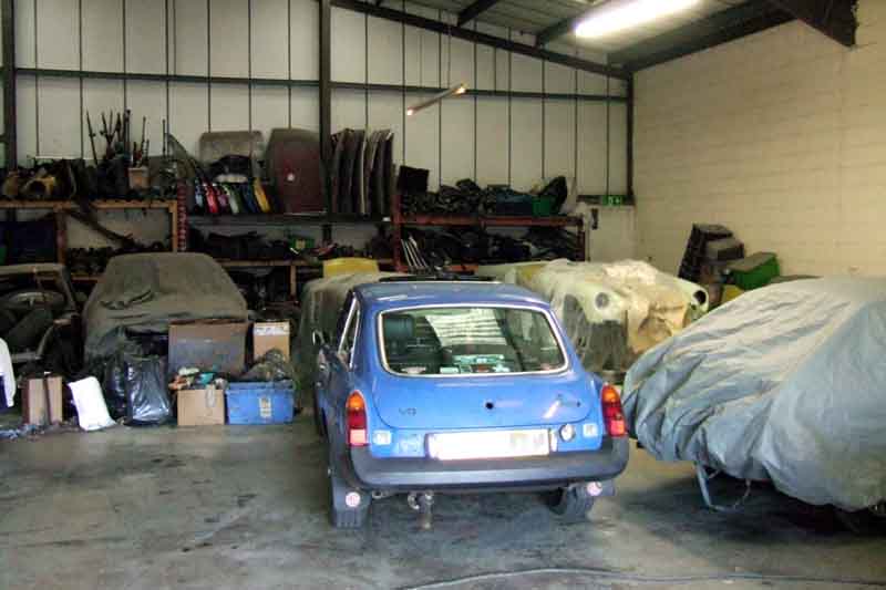
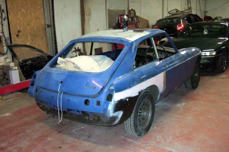
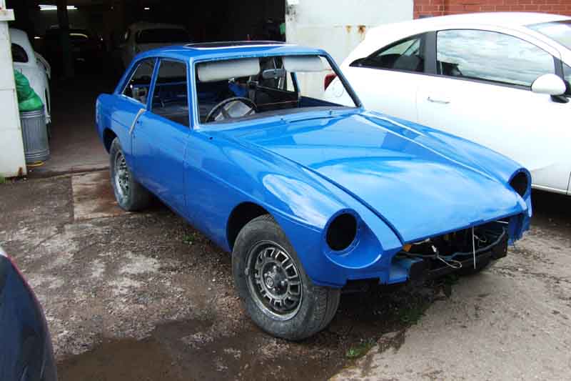
23rd September 2016: Before delivery I decided to remove most of the external trim, taking careful measurements and pictures of the V8 and BL badging which are stuck on, the 'MG BGT' badge being on pegs. A 'garotte' of thin wire made short work of getting the stuck badges off, without any damage to badge or panel - ironic given that the badges are to be replaced and the panel painted.
Forgot the mud flaps, ran out of time for wipers and washers and heater intake.

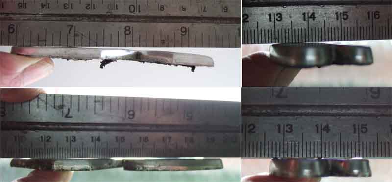
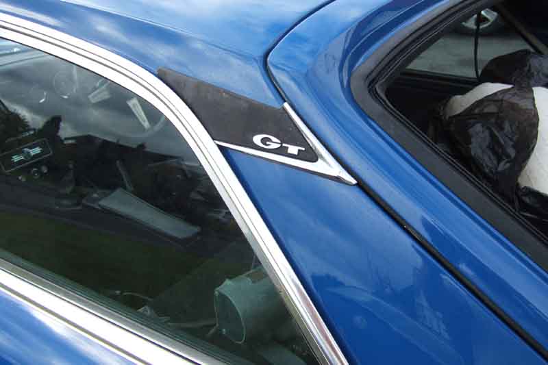
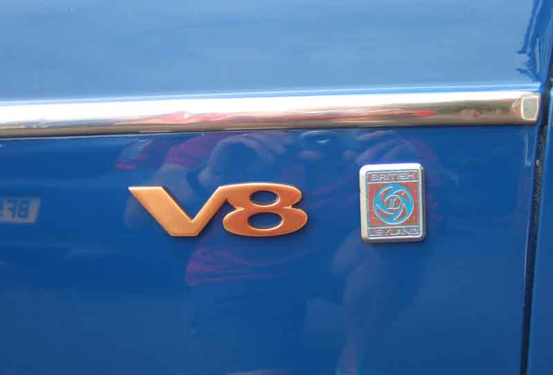
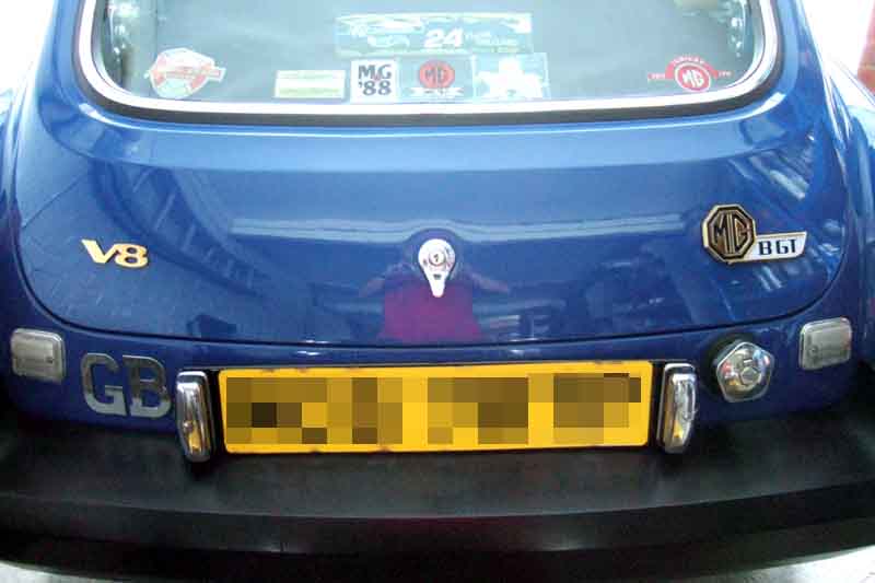
All Vee's badges were 'silver' when she came to me, although with a September 1975 build date she is eligible for the 50th Anniversary 'gold' badging. However the passenger wing and tailgate 'V8' badges are gold on the back, which is strange. She also had V8 and BL badging on the drivers wing, which isn't original, and that V8 was silver on the back. I wondered if that was because it was a replacement wing with holes for pegged badges, but they were stuck on. It's a slightly different shape to the other two, indicating it was a subsequent addition, so a bit strange. 'A' is an 'original' badge with the adhesive still on. 'B' is the other original with the adhesive cleaned off - quite clearly gold on the back. 'C' is the extra and non-standard badge from the drivers wing - quite clearly 'silver' on the back. 'D' is one of two new gold badges I have ready for fitting, obtained from different sources at different times, and with different 'shades' of gold. It has been said that with one on the back and the other on the wing no one will ever notice ... As I need to get front bumper 'MG' and tailgate 'MG BGT' badges in gold, I may get another V8 and hope it matches with one of the others.
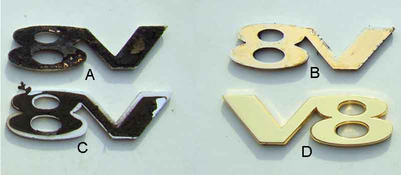
The tailgate 'V8' badges were originally curved in two planes, whereas the wing badges are flat. Tailgate at the top, wing at the bottom. Only the flat badges are available now, but being alloy are relatively easy to curve along their length, at least.
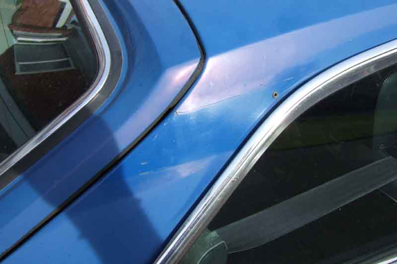
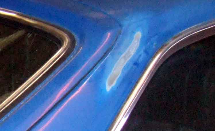
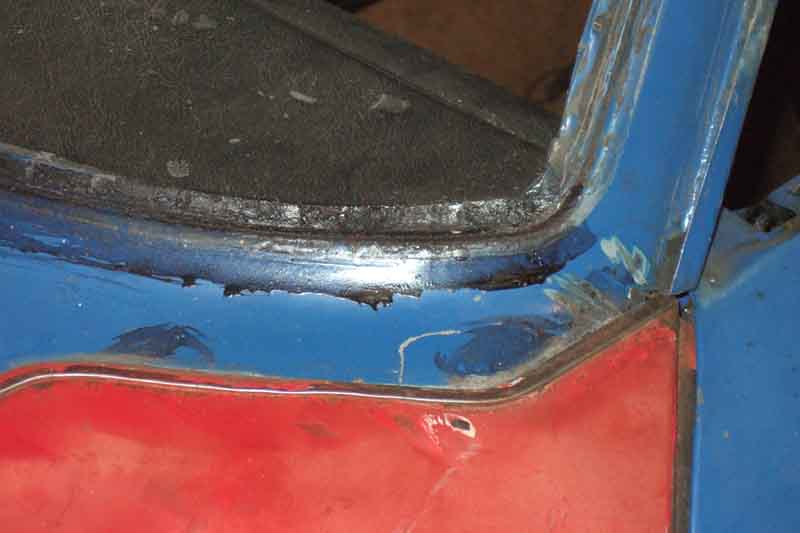
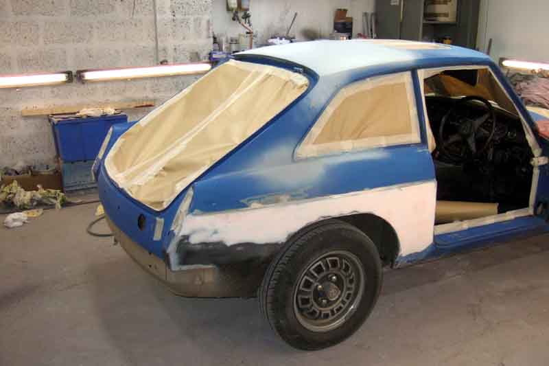
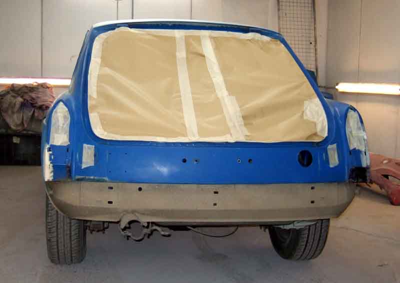
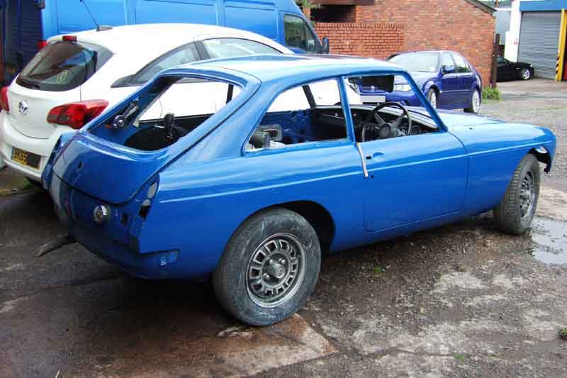
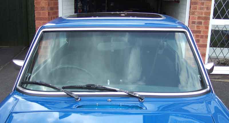
Another oddity is the 'Spocks ears' at the top of the C-panels. According to Clausager these were only fitted from March 76 when the body plant decided to stop lead-loading the seams. Vee has them, although she was built in May 75. I'd taken the 'ears' off many years ago to repaint them, and I would have sworn on a stack of bibles that there was a visible seam underneath. Imagine my surprise when on removing them this time there was no visible seam! Who would go to the bother of retro-fitting them? However there does appear to be a join in the paint at the upper edge of one of them at least, so maybe it was done as a partial repaint. Or maybe being close to the changeover point C-posts arrived with peg holes, and no-one told the body man not to lead load them. That's if they are lead-loaded, and not fillered. If the roof only was repainted at some point, it needs stripping to bare metal again as there are a number of small rust spots. As an aside there is a visible line around the windscreen rubber showing the scuttle was repainted with the screen in.
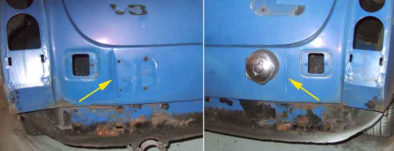
C-panel to roof seams are lead-loading and not fillered ...
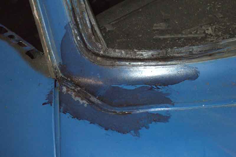
... but the rear panel seams are visible, and in the positions they were while lead-loading was being carried out. It's not a replacement panel as the body-man says it is all original. I've decided to do-away with the 'Spocks ears' as they were never made in gold and they won't match the rest of the badging ... or will I?
A similar situation applies to a small chromed trim piece at the top of GT A-pillars covering the join to the roof - AHH7828 and AHH7829. Clausager says they finished (ho ho) at Feb 68 chassis 141237, "as the join here is now solder finished". More likely lead-loaded? Until March 76? Vee doesn't have those but seemingly (ho ... perhaps not) should, but that's far more likely to have been removed for painting and not bothered refitting if not lost.
No going back, how will it all turn out, I wonder ...
Week 1:
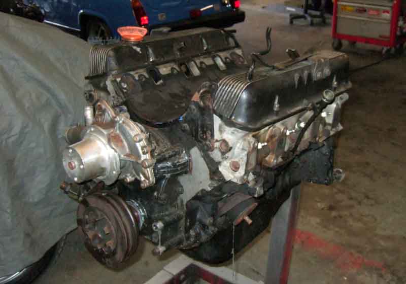
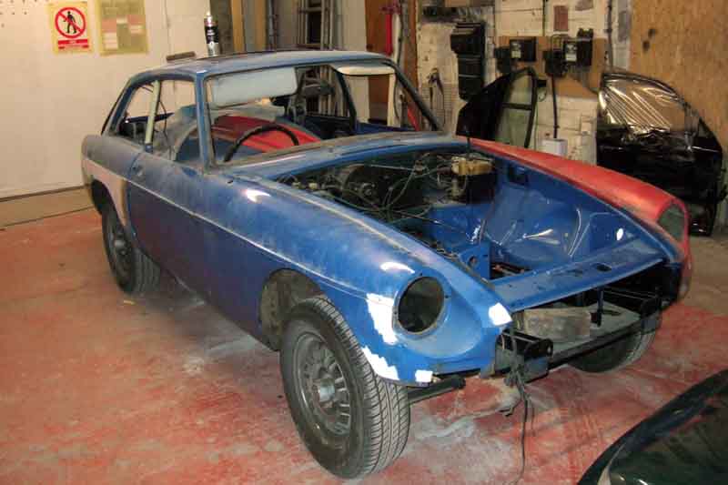
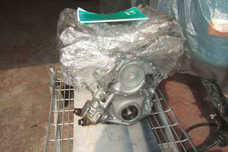
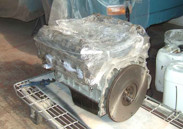
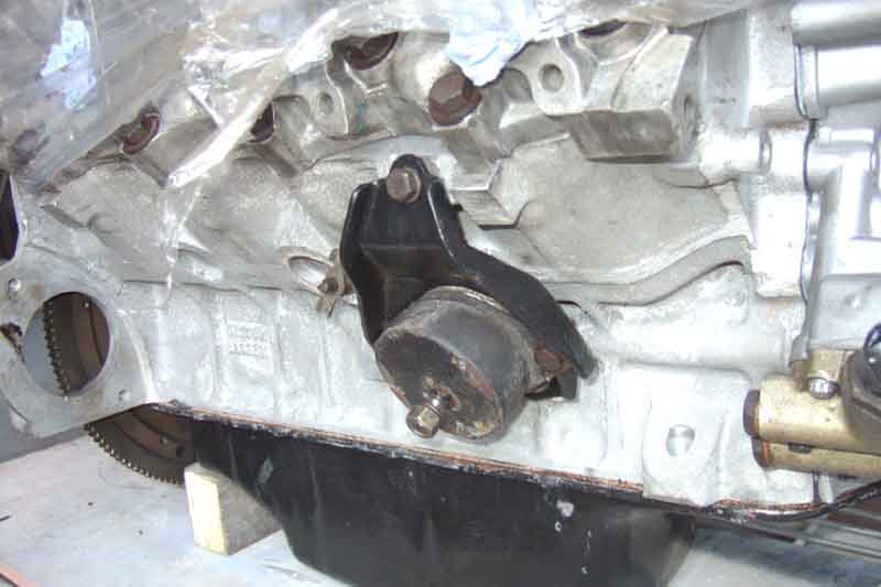
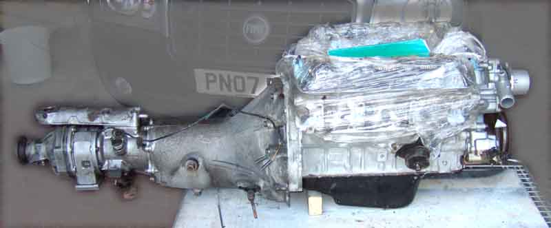
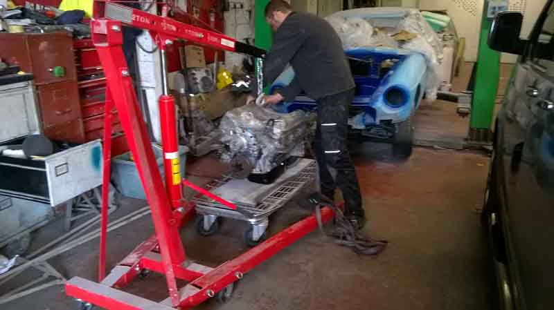
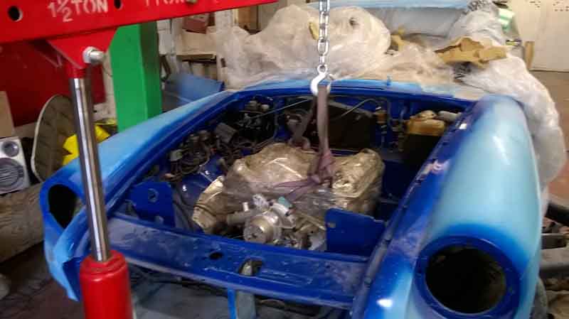
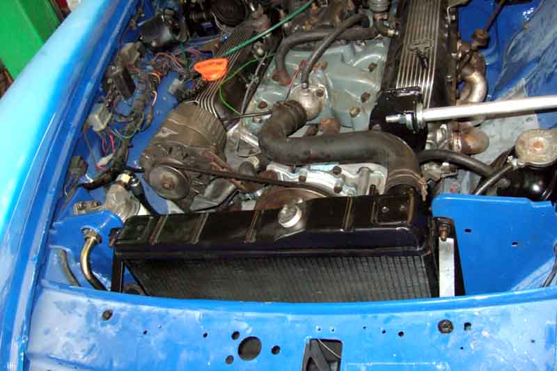
Engine out ...
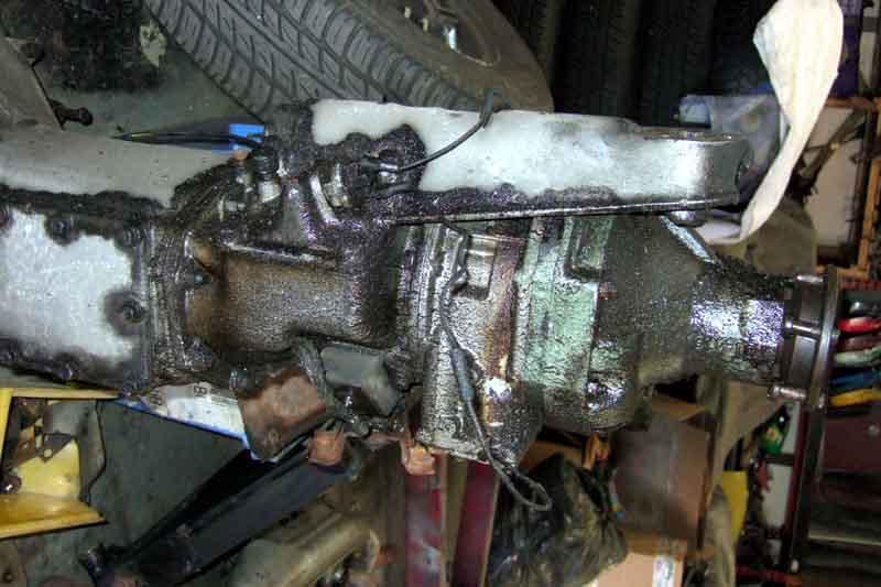
... with gearbox ...
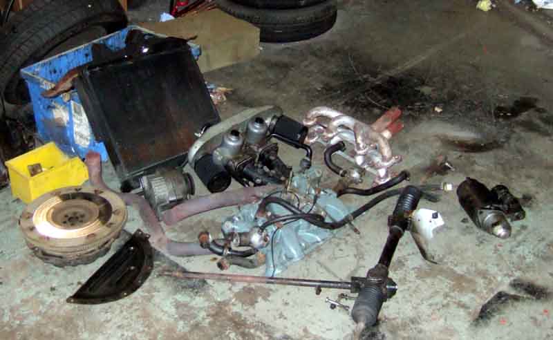
... after removing all this ...
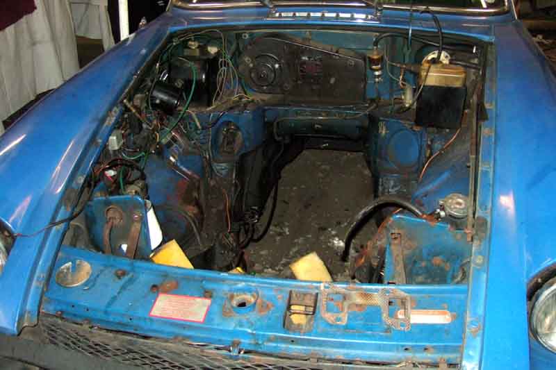
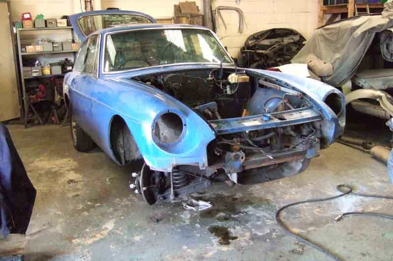
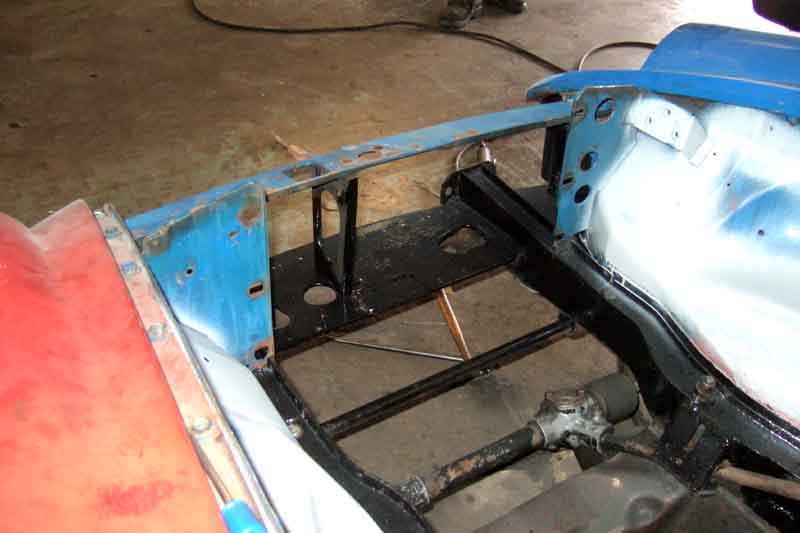
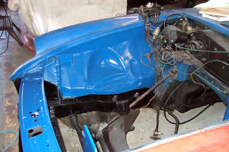
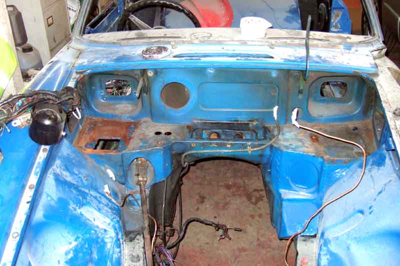
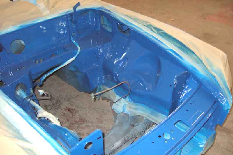
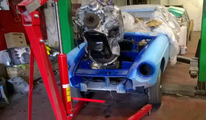
... to leave an empty engine bay. Pondering how much to remove from here to tidy-up the bay.
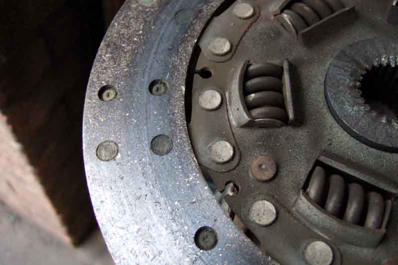
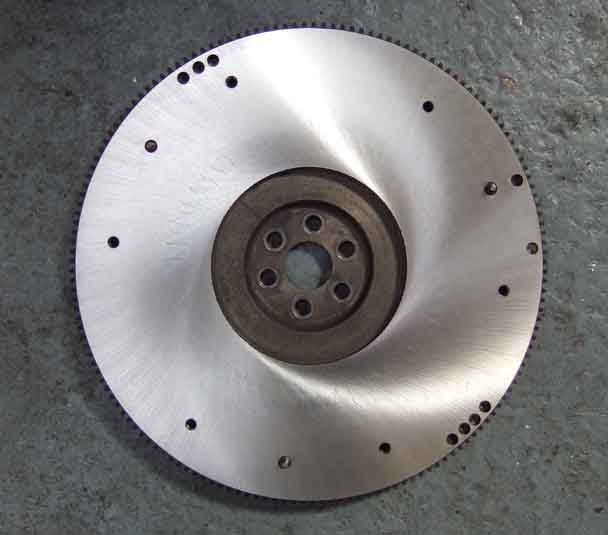
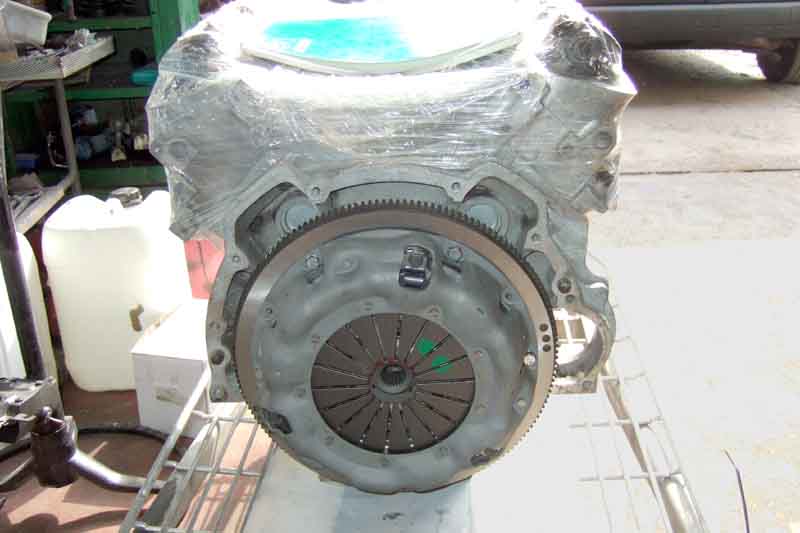
Clutch nearly down to the rivets on the flywheel side after over 100k ...
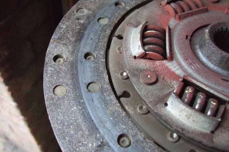
... a bit more meat on the pressure-plate side, but an odd mark in the middle of the friction material. Oil? There had been no sign of oil anywhere else on the clutch or bellhousing. Whatever it is, I wonder if it has been causing the clutch-drag after not being used for a bit.
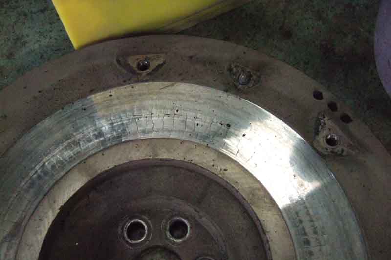
However the flywheel will still need a skim.
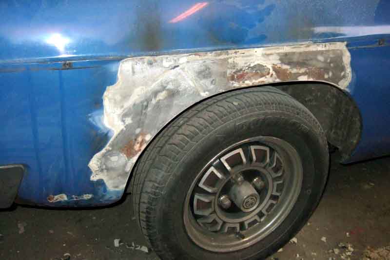
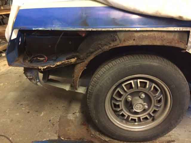
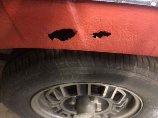
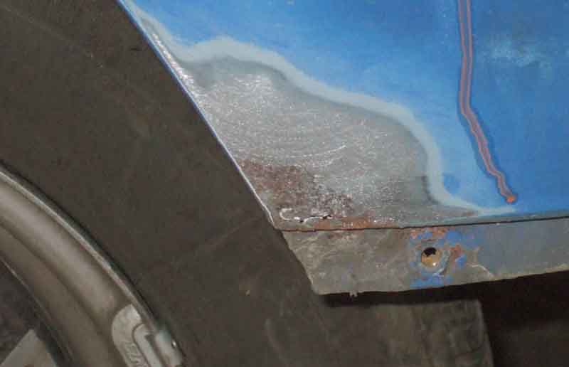
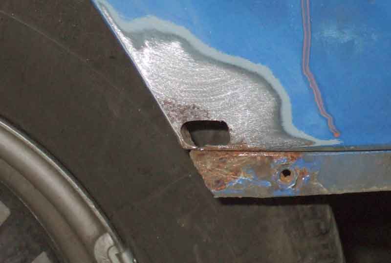
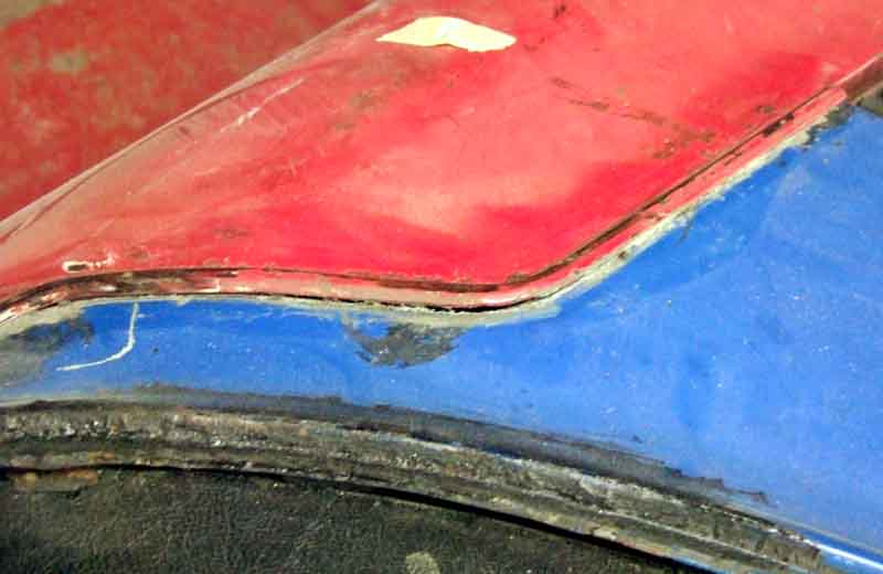
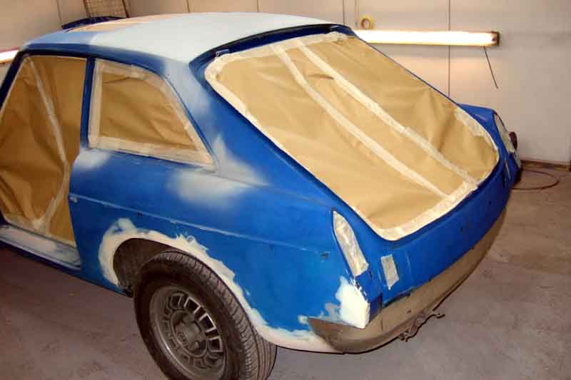
The source of the bubbling over the OS rear arch is two sections having been let-in in the past but rotted through again, probably inadequate rust-proofing after fitting. The rest of the wing is good enough to cut out those patches and replace them.
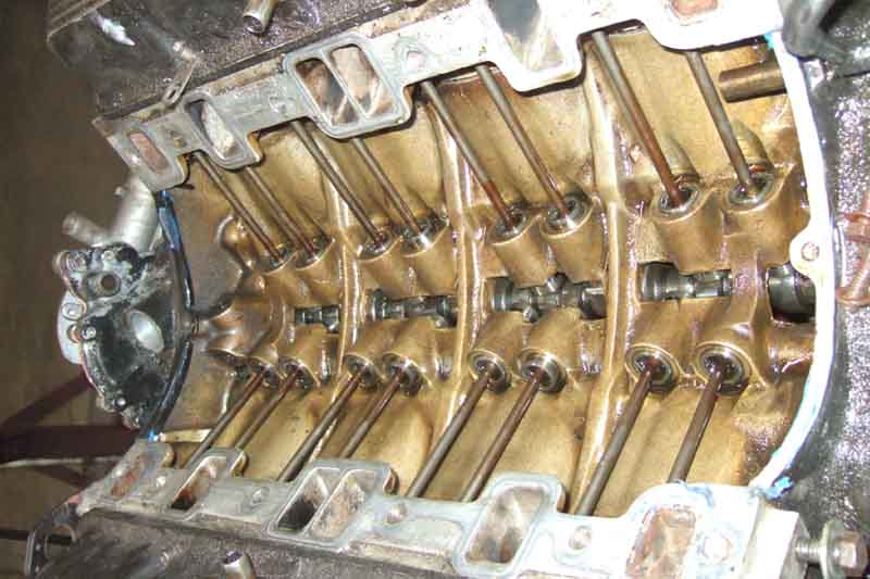
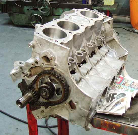
Very clean internals, a tribute to 3k oil and filter changes.
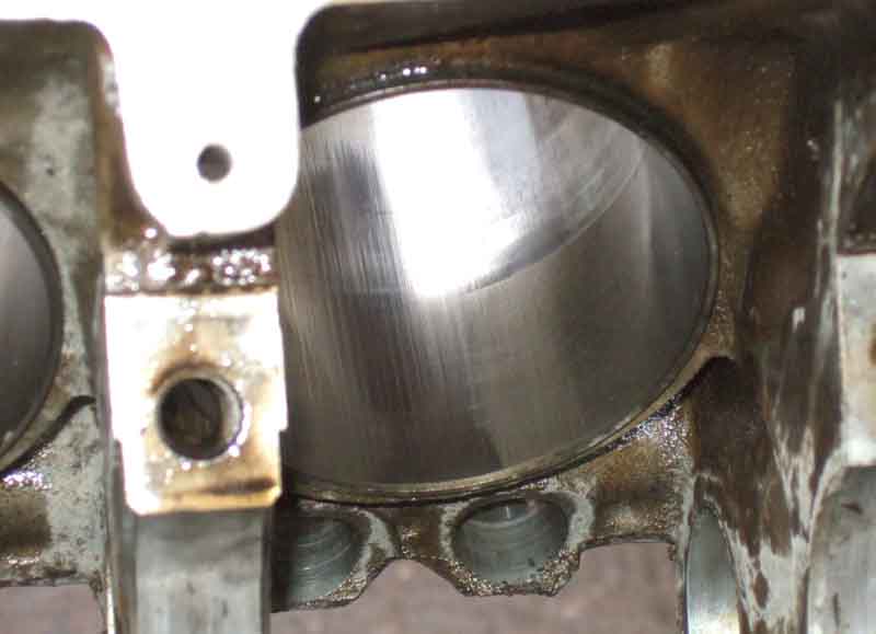
But after that it is all bad news with bad scuffing from piston-slap, worse on the left-hand side which ISN'T the side that had the con-rods round the wrong way for 100k. Pistons were plus 20s so a past rebore, although the crank wasn't reground. Also the pistons were biased with a thrust-face and stamped 'FRONT' on top at the edge, something I'd not noticed in the past as I'd left a ring of carbon. Nothing in the WSM about biased pistons, and another set of standards I have are not. Could it be the biasing that has caused the piston-slap?
Even worse was this lump of gravel found in the crankshaft oil gallery! Fortunately too large to pass through the oil hole in the shell to the journal, and seemingly irregular enough to allow enough oil flow to occur and not damage anything.

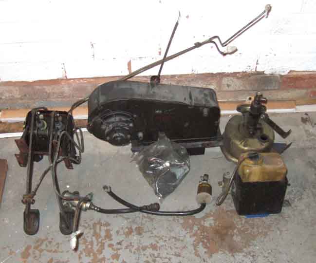
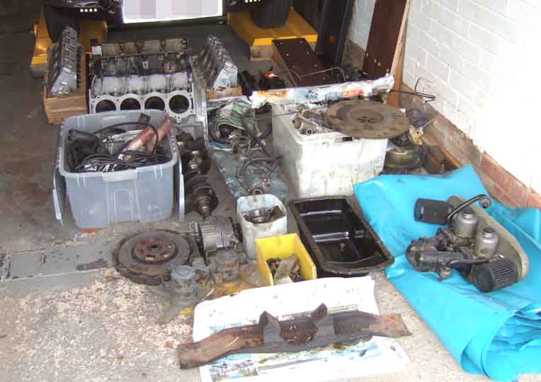
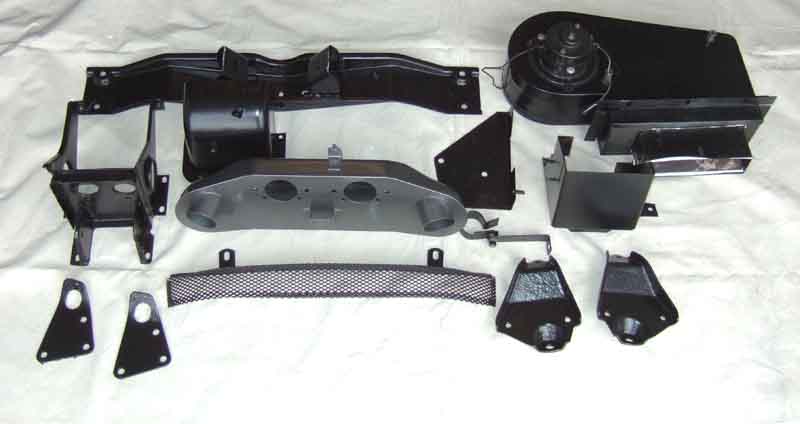
You need all this plus the block and ancillaries just to suck, squeeze, bang and blow.
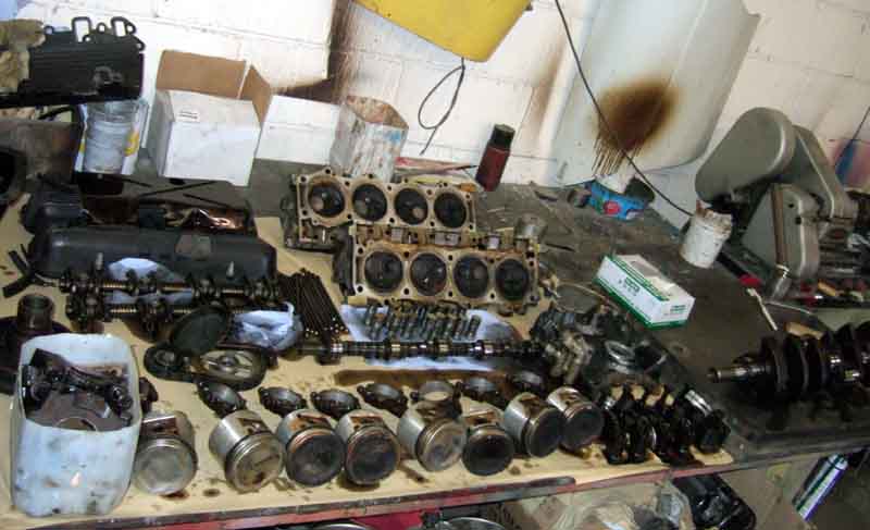
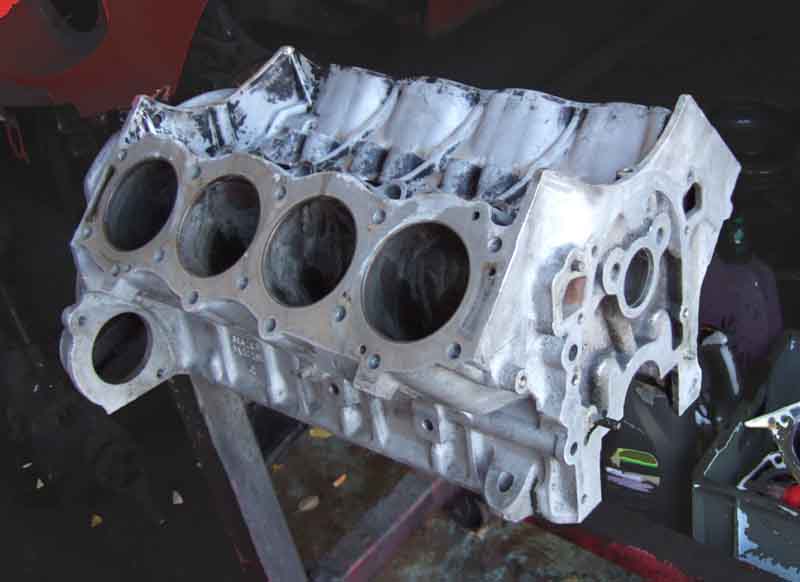
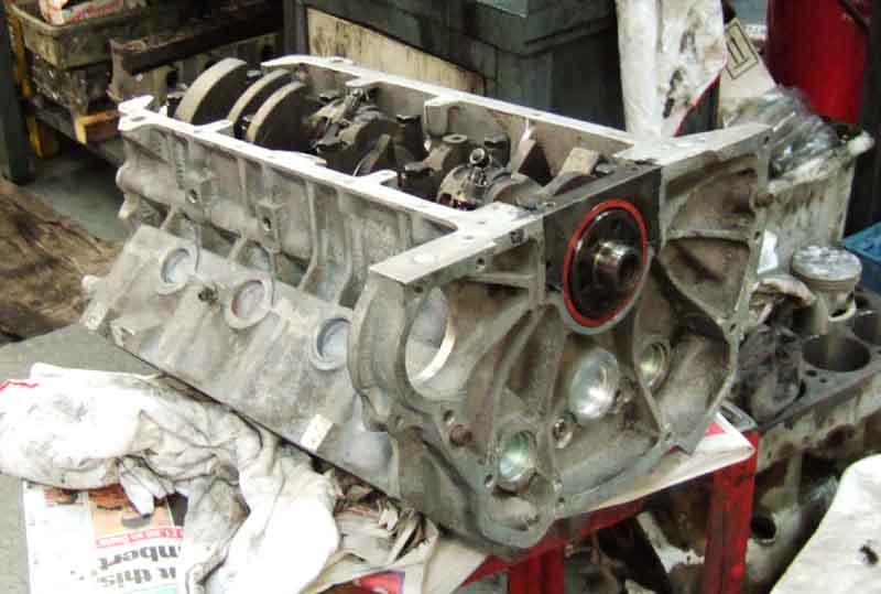
This is the block I'll be using, as mine is already at plus 20. You can get plus 40 pistons, but it leaves the liners pretty thin, and I'm wondering if it is a rogue block anyway having needed +20 in its first 100k, without a crank regrind (which will be done this time).
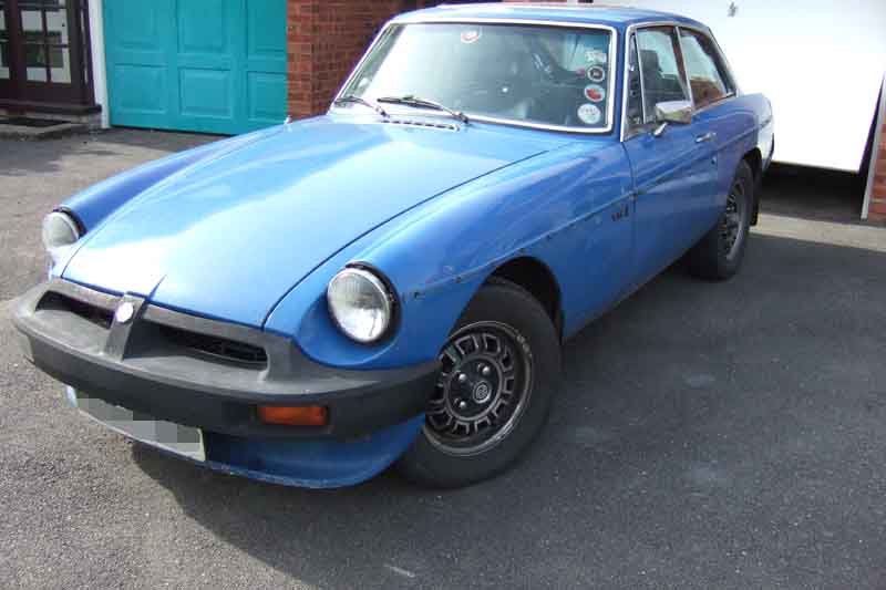
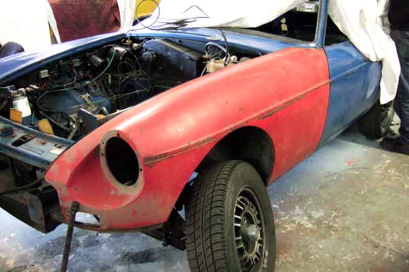
Front stripped ...
NS wing removed that I crumpled ...
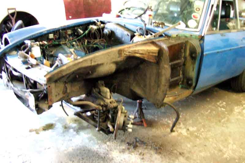
... A little bit of rot in the top of the (previously replaced) trumpet section, duly cut out and replaced.
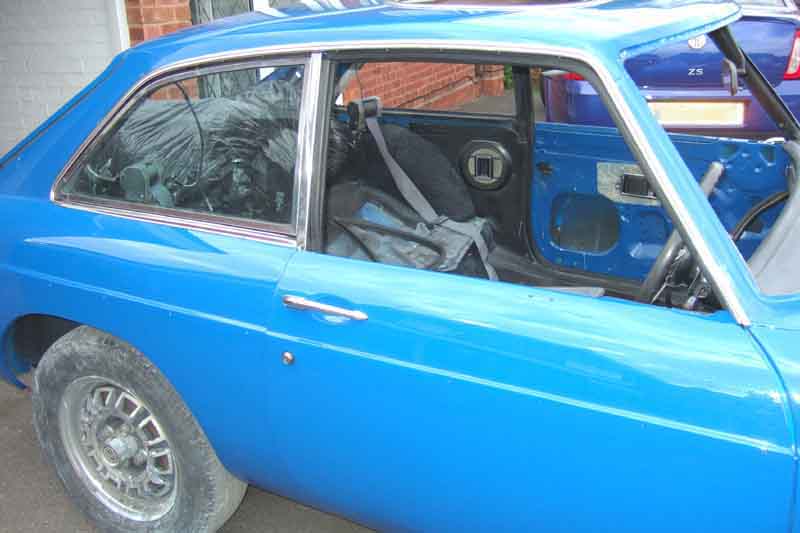
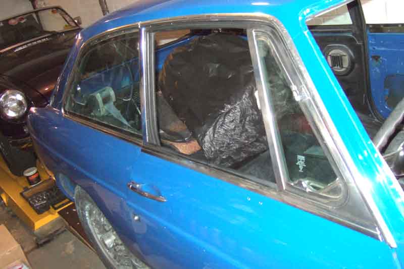
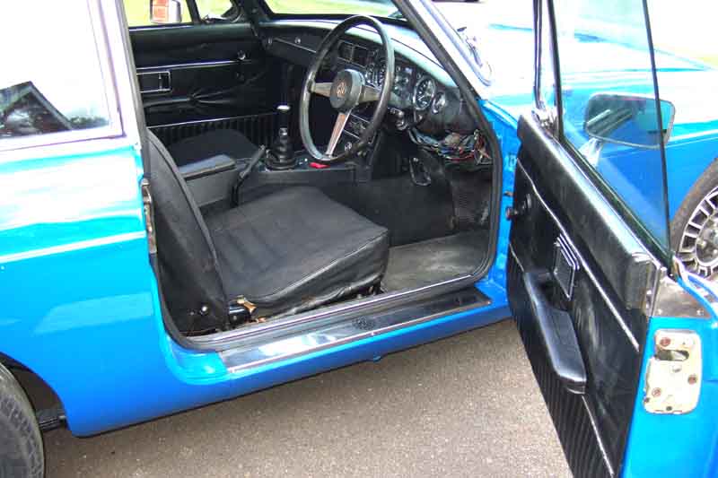
I stripped the doors and removed the side windows and trim.
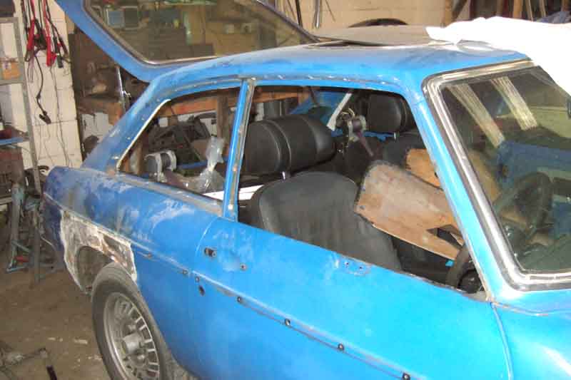
Sunroof removed - a joint effort as we pondered how it had been installed ...
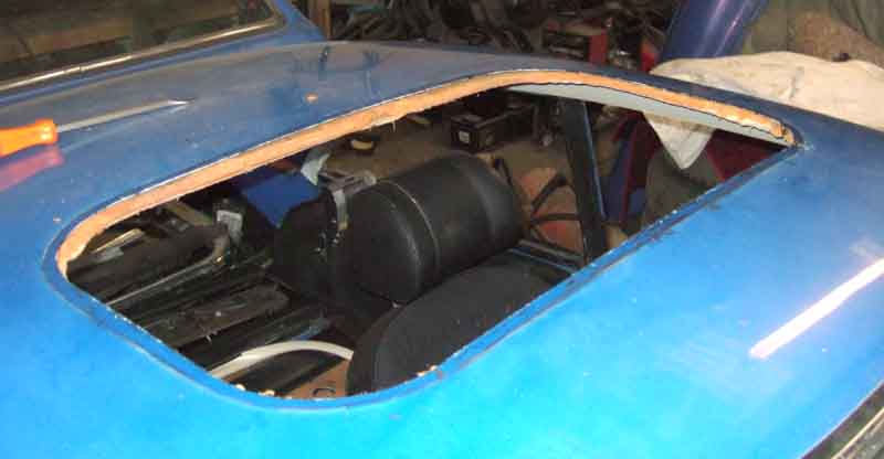
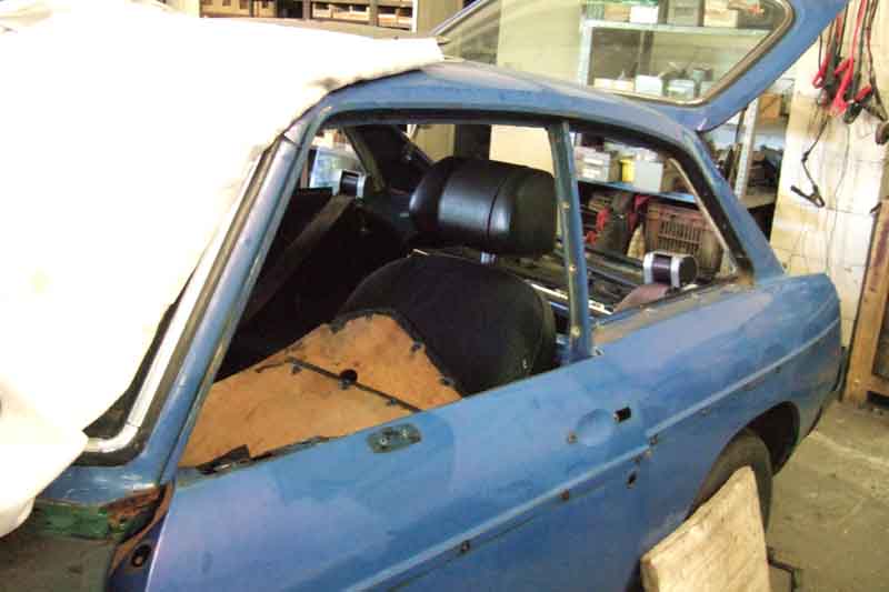
... showing the headlining is little more than compressed orange fluff with a sheet of card and vinyl underneath.
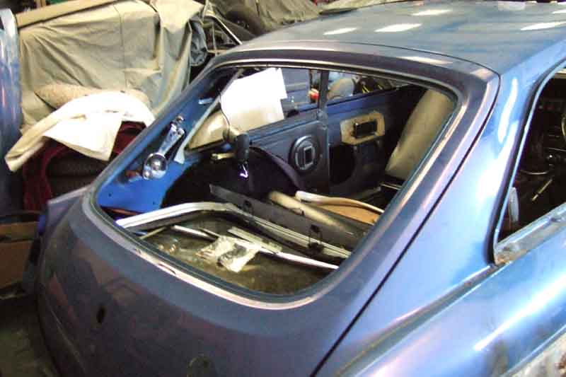
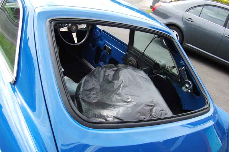
Front ...
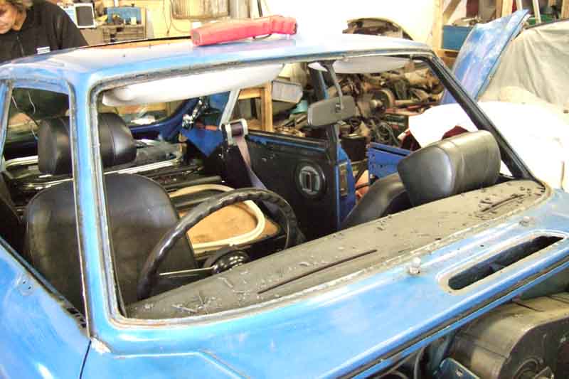
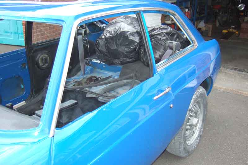
... and rear screens, and much of the internal trim removed, not much more stripping to go.
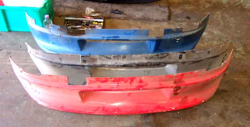
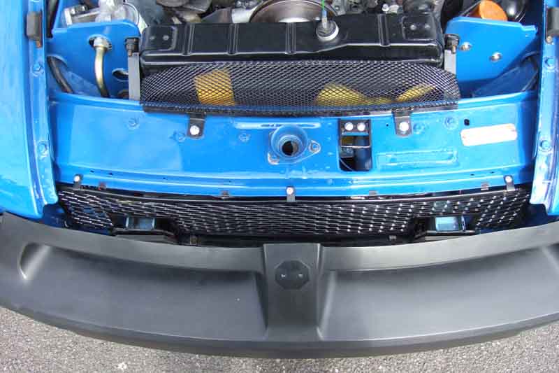
I'd caught the Special Tuning valance twice in the past putting two bad cracks in it ...
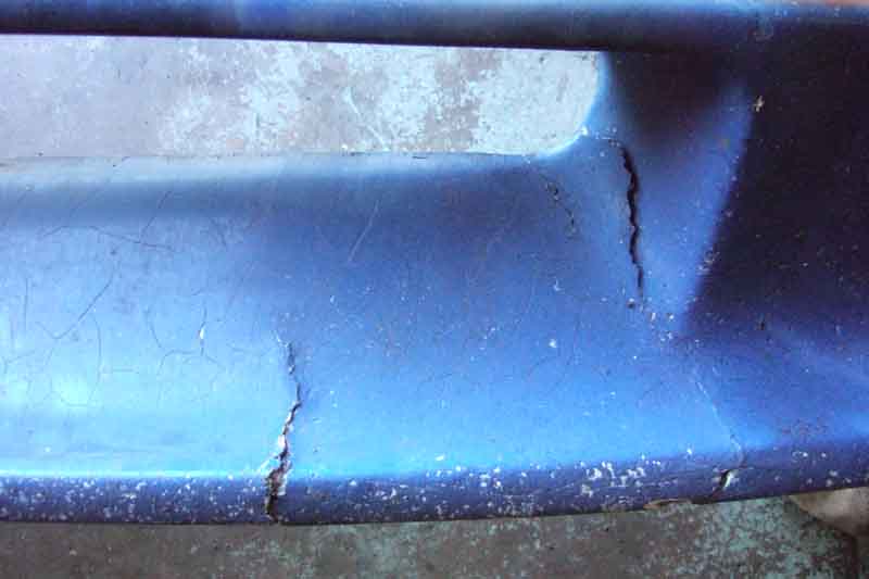
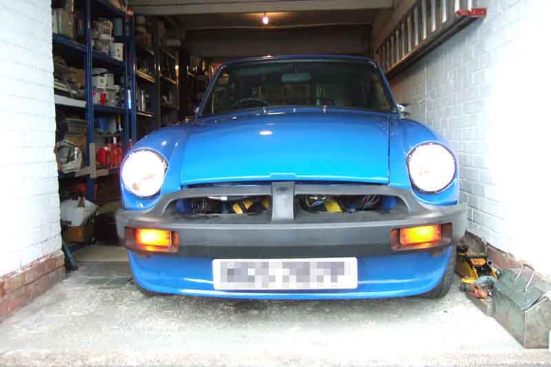
... and have selected the red one to replace it. Talking to others it's apparent that these (STR 0189 air dam) make a huge difference to cooling, as well as reducing drag and lift.
Replacement wing fitted
No rot in the lower corners of the front screen aperture, just light rust, which gets a scrape and treatment.
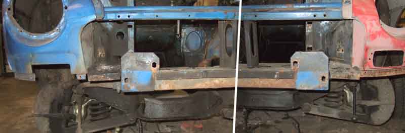
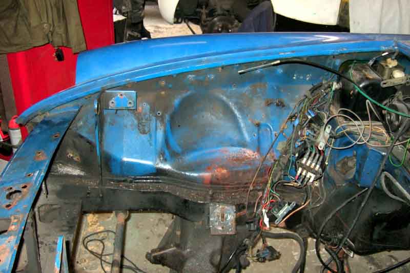
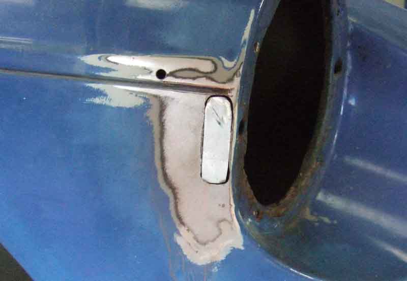
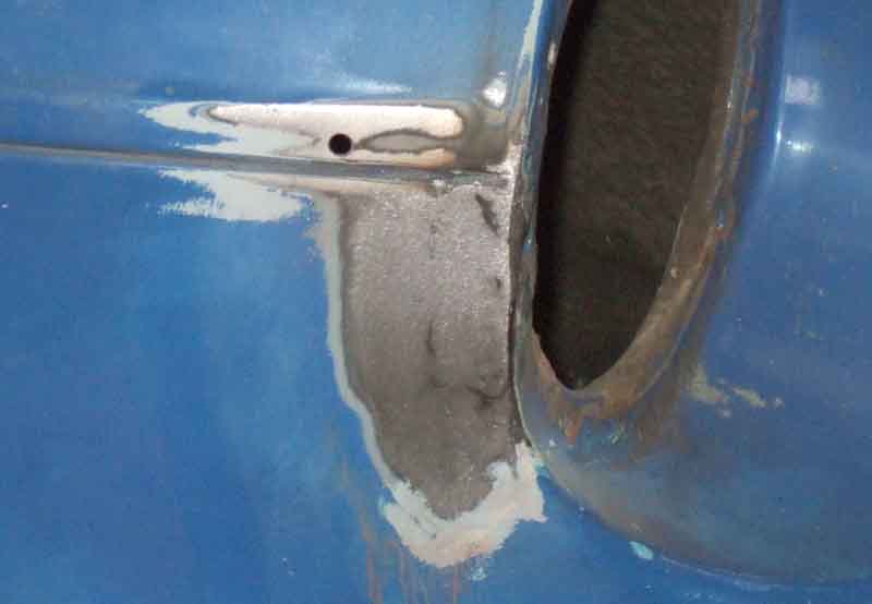
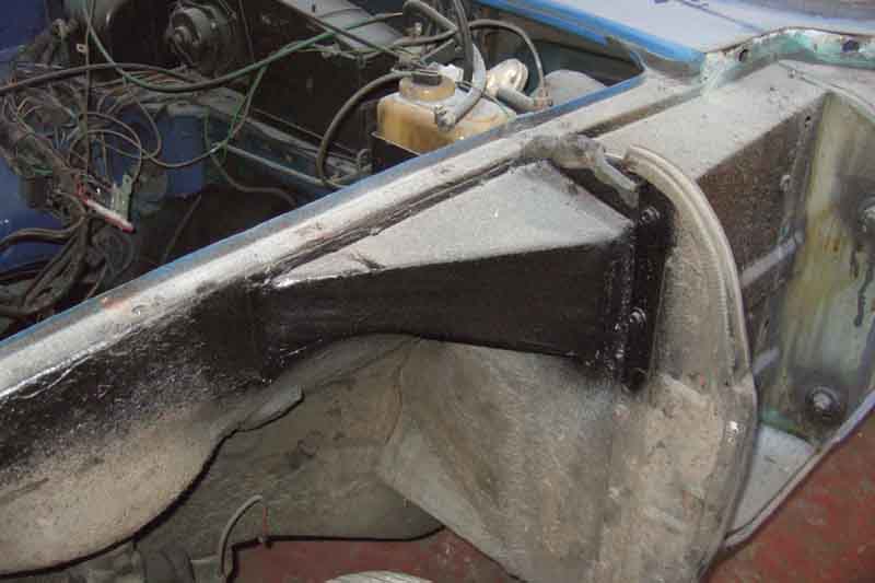
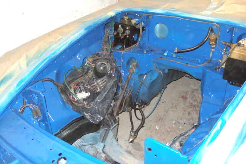
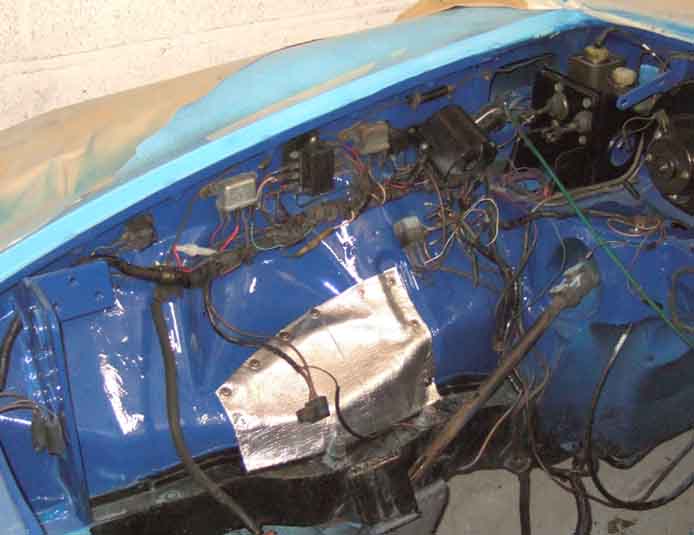
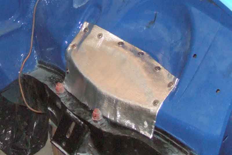
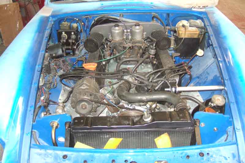
After pondering I decided to completely strip the front and sides of the engine bay as trying to clean/paint round this lot would be a pain. Incidentally the shiny plate below the fusebox is stainless steel fitted after patching up the inner wing which had rotted through due to a combination of impact from the tubular manifolds and heat, using a convenient pair of already tapped holes, for who knows what. The other side suffered nowhere near as much, although I may stick heat insulation both sides after painting - if I can find any!
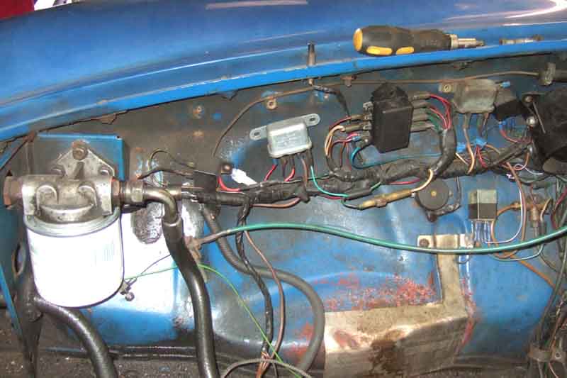
So out came the oil filter, hoses and cooler, the horns and the harness, bonnet latch and safety catch, and the commission and chassis number tags.
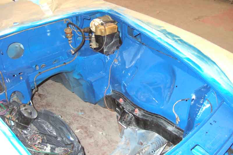
Then everything off the sides back to the pedal-box ...
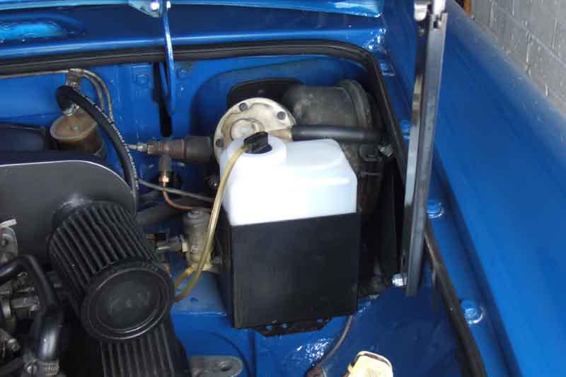
... as well as the coil and expansion tank on the other side. All the fasteners came undone with the exception of the O/S horn bracket screws which had to be drilled out. You have to be careful with the studs on the expansion strap as they are welded to the strap and it is easy to buckle that, but they were no problem. The rear of the bay will have to stay as it is, apart from the washer bottle and pump it's a lot of work to remove servo, pedal box and heater, and really that area is only mucky so cleanable with a little brush, no rust from leaking hydraulic fluid.
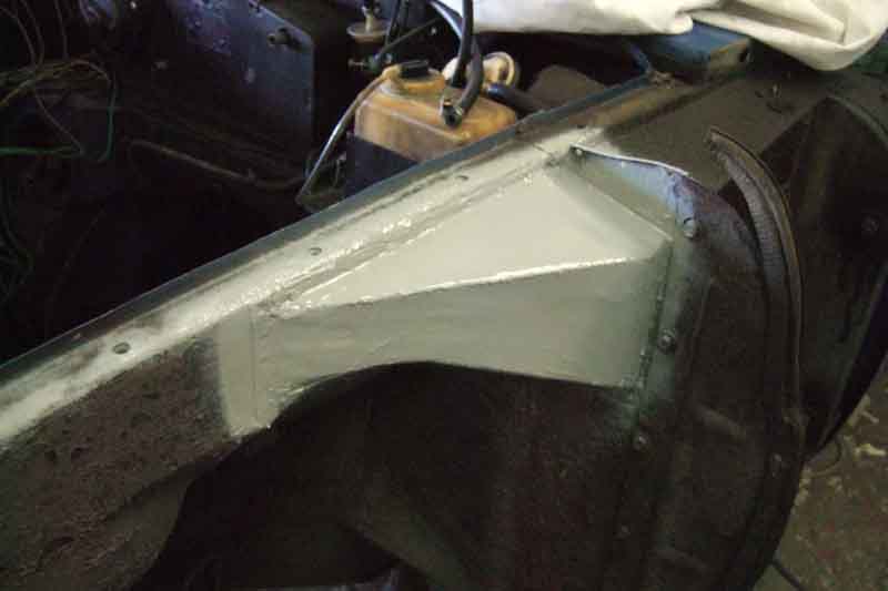
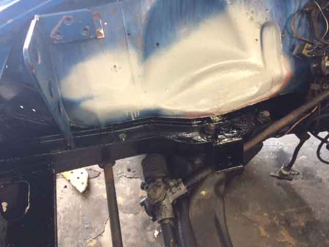
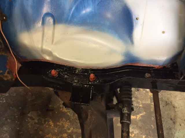
Next day the panels were cleaned, de-rusted, primed, and the chassis rails painted. The panels just above the engine mounts were also dressed back a bit to give more clearance for the tubular manifolds, which had been hitting them despite a 5mm spacer albeit only on the drivers side. I made a second spacer for the passenger side to increase clearance even more.
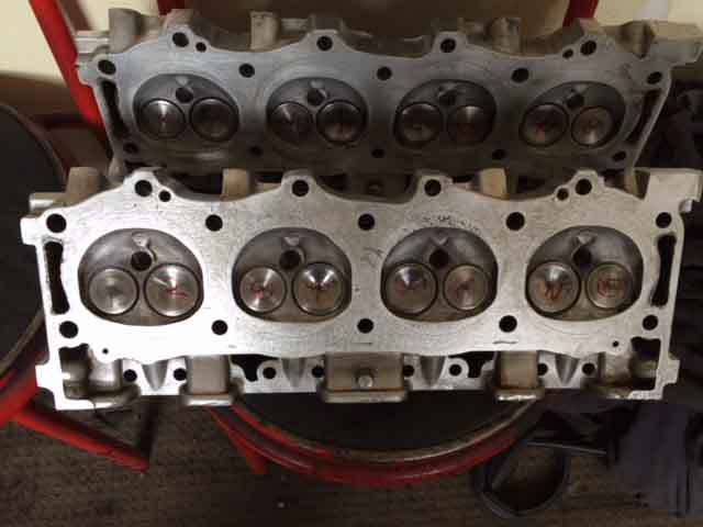
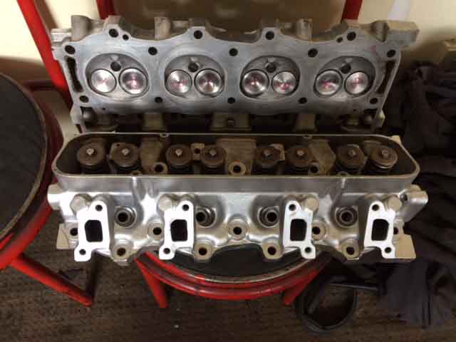
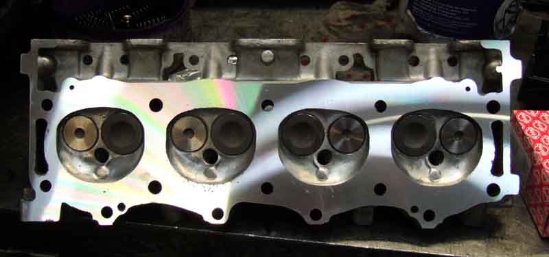
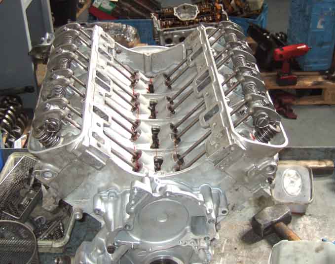
Heads stripped, cleaned and rebuilt. These heads are from Perry Stephenson, having stripped two plug threads on the originals. I'll probably get those rethreaded with Wurth Time-Sert inserts.
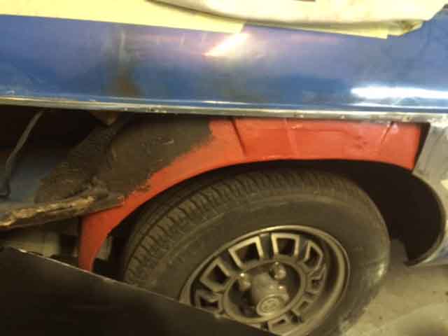
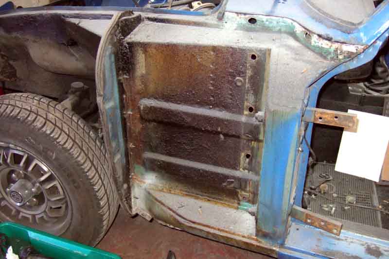
The iceberg principle lives. When they started cutting back the outer wing was worse that it looked from the outside, so needs most of a half-panel. Fortunately the front third is sound which saves much fettling of a replacement panel to the door opening and sill as well as the rear light plinth. Obviously not treated following previous replacement, it'll get done this time, as well as the other side.
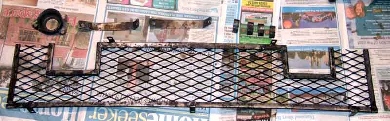
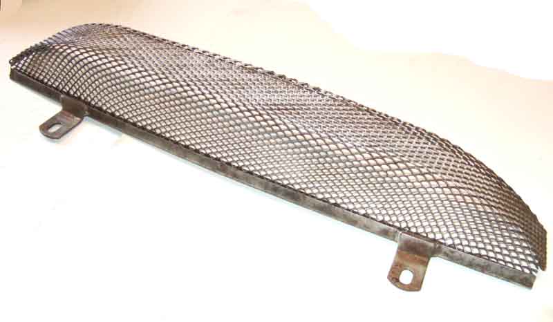
At home I derusted and treated the front grille, radiator struts, bonnet latch cup and harness clips. I'd left the bonnet safety catch bar at the workshop, so that and the screws and bolts will done another time.
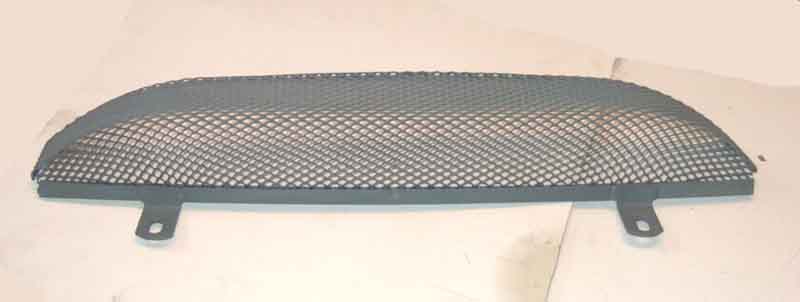
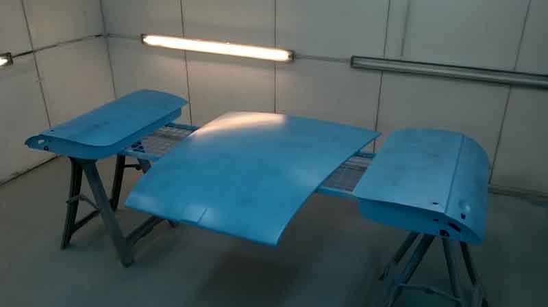
Primed, then finished in satin black ...
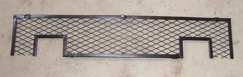
... and body colour.
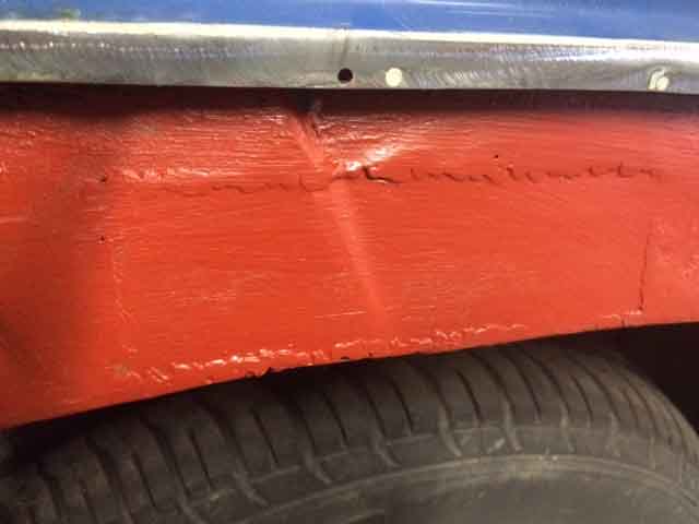
Given the mess on the outer panel I'm surprised this is all there is on the arch, but is shows how the very narrow gap between the two panels build up crud and rot both panels, the same as the sill cover panels.
The repair panel even has the crease :o)
Week 3:
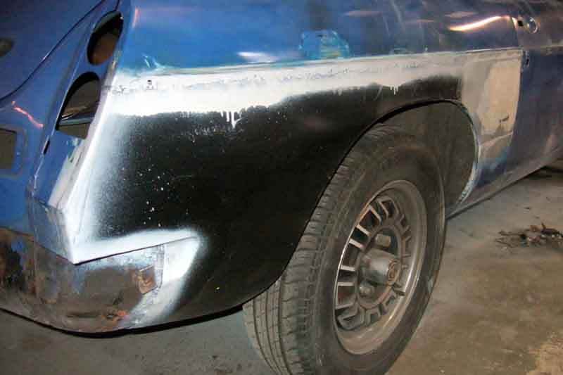
Rear wing repair fully fitted. Subsequently the body man was very uncomplimentary about it and had to do a lot of reworking to get good panel alignment.
What started off as a pinhole by the OS headlight ended up as a patch a couple of inches square
Invisible mending.
A couple more at the lower corner ...
... but a smaller patch required.
Chassis rails and apron were black when I got it, so they can stay the same. Slam-panel and radiator mounting panels to be derusted and feathered-in, then the engine compartment can be painted.
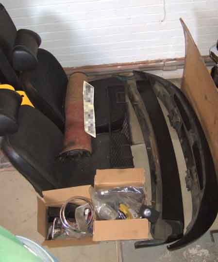
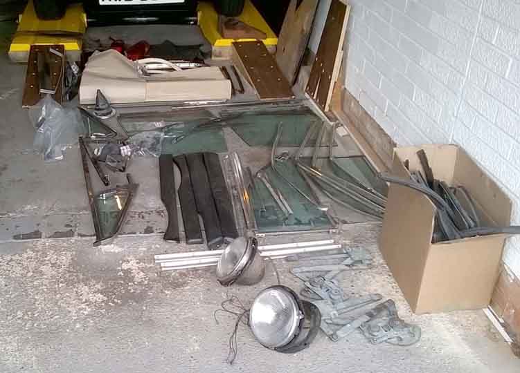
On this visit I brought the bumpers back home, to get them out of their way as much as anything but also for cleaning and polishing, to join the seats I had previously brought back together with other miscellaneous parts for painting. The seats are to be recovered, but I shan't do that until I have Vee back home again, when I will also refit the bulk of the trim. I'm not planning to replace anything other than the seat covers initially, all the other stuff is in reasonable nick, and I prefer it to be 'showing its age' rather than pristine as it is for driving, not showing. The boxes do contain some new bits, but mainly fasteners, plus new oil hoses and an engine steady bar. Both inner wings were showing dents from the tubular exhaust manifolds, and although I've had them dressed back a bit I decided to fit a bar as well.
Week 4:
Slam-panel and engine bay painted.


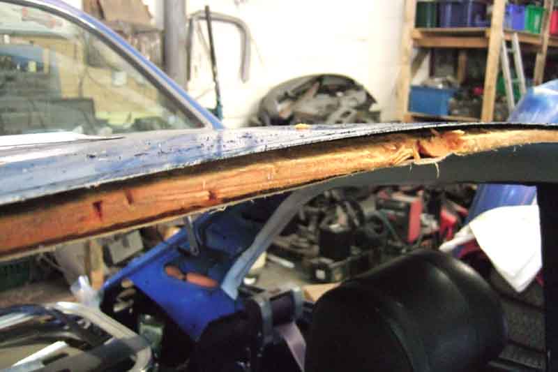
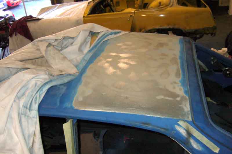
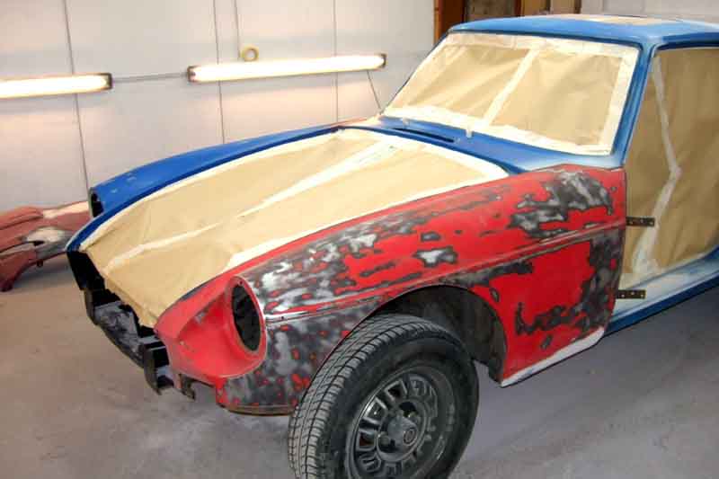
Rear half of the roof stripped back to metal. The paint was cracking and beginning to form scabs where cracks joined when I had the car 22 years ago. I'd treated the scabs which stayed sound, but others had been forming very slowly. When I had the roadster painted he advised me to go back to bare metal, because with multiple repaints the underlying layers can crack as each layer above it progressively shrinks. Certainly paint does shrink over time, on the scabs I'd painted I left them level but after a while they were visibly recessed, and it looked like that is what had happened here.
Radiator, expansion tank, bonnet prop and number-plate assembly brought back for cleaning and painting, the engine has gone to the machine shop. That's it for visits now I think, until the engine comes back, then while it is being rebuilt I shall replace everything in the engine bay. I've also decided to keep Spock's ears. In theory it shouldn't have them, but it seems completely mad for someone to go to the trouble of retro-fitting them, and even though the C-post seams have been lead-loaded the rear panel seams haven't, so it may well have come out of the factory with them.
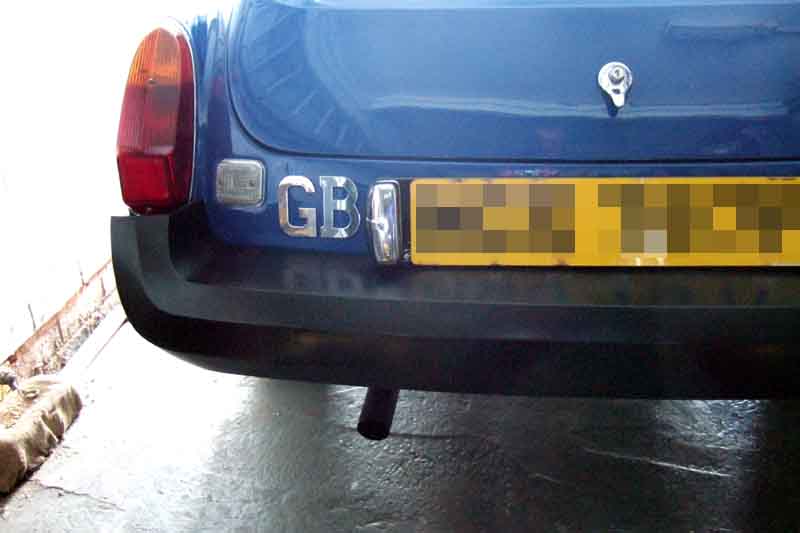
Stripping the rear number-plate (needs a new backing plate like the front) I was annoyed to break a stud on one of the light units, which are otherwise in as-new condition. Still, a bit of thought and 'engineering' and I was able to replace it.
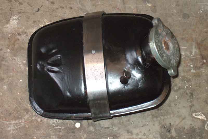
A bit of cleaning and painting makes a world of difference:
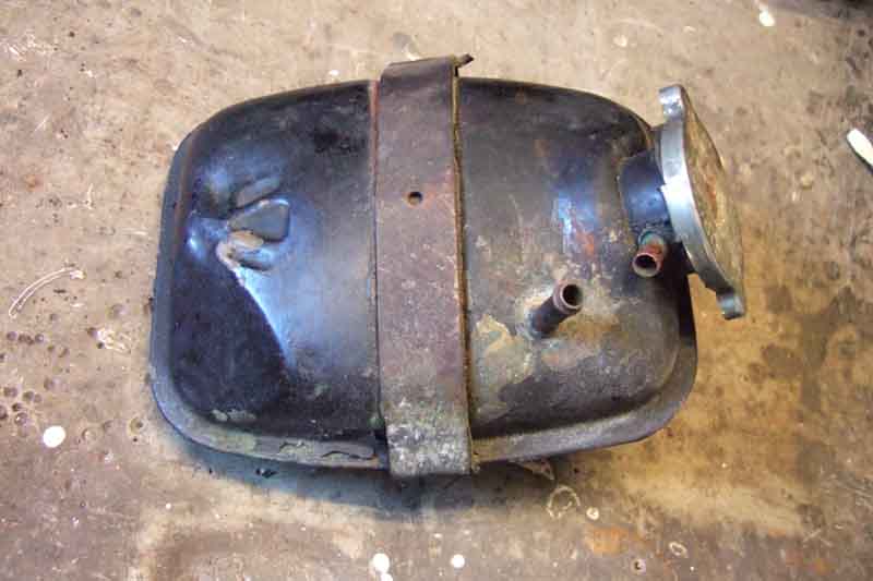
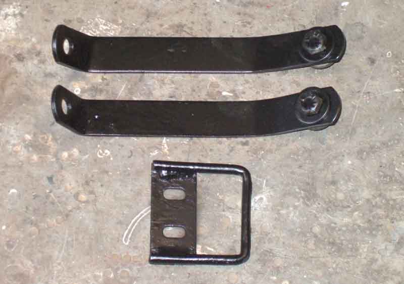
Hammerite Special Metals primer, I think the strap is anodised, so although it looked really rusty it cleaned up very easily.

Satin black over the primer, needed several coats to cover the red primer. Grey is recommended but probably wouldn't stick to the brass as well as the Special Metals does. There is a rubber strip under the strap, and two more glued to the back.
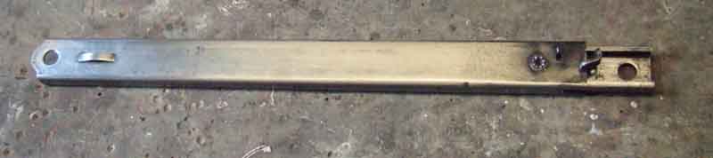
Other tasks have been the bonnet stay, similarly anodised and looking like the expansion tank strap, but cleaned up well. Settled for clear-coat on these, rather than silver.
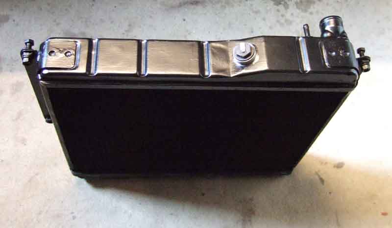
Also the radiator, which only needed a bit of rubbing down, then Special Metals primer (brass tanks) and satin black
Turtle Black Chrome brought the bumpers up fairly well. But where the sun had been beating down it had left a roughened texture that remained, compared to a smoother surface with more of a shine on the lower parts you can't normally see. So tried black shoe polish on the flat parts under the rear light units, which made a difference, so applied that to the whole bumper.
November, December and January nothing doing at all.
February: Since October no progress at all apart from regular promises of 'next week' for the engine from one of the two people involved - the office man. I had no contact details for the other person - the spanner man, and speaking to the people in the next-door unit there had been virtually no activity during December and January, by all accounts due to major domestic issues for the office man and illness of the spanner man. In February I sent the office man an ultimatum saying unless the engine was back that week ready for my inspection and reassembly I'd have to make other arrangements. Quite by chance next day I rang the unit next door to be told that the bailiffs were in changing the locks! Dashed round, to find two other owners there trying to find out what was happening ... and no car! The bailiff allowed me a quick look round and as far as I could tell everything else was still there. Some different cars in there from my last visit, so something has been happening in the meantime. Again by chance one of the other owners had contact details for the spanner man. There was a flurry of texts back and fore, apparently the car was at the paint shop. I went round there, and now they are doing a more comprehensive job to my instructions, they had only picked up the car two days earlier. Next day the spanner man said he is sorting the money problems out, is being allowed to finish all his in-progress work, and the office man is no longer involved, all confirmed by the bailiff. Still need the engine parts back though ...
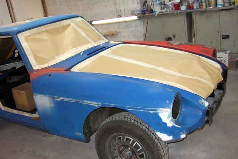
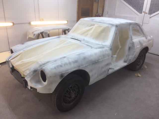
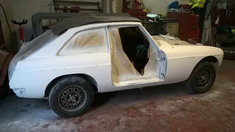
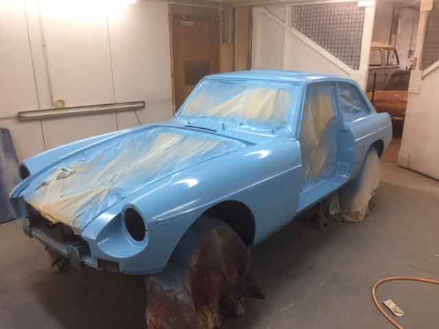
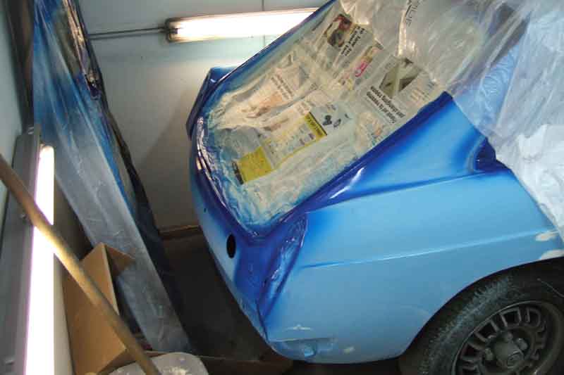
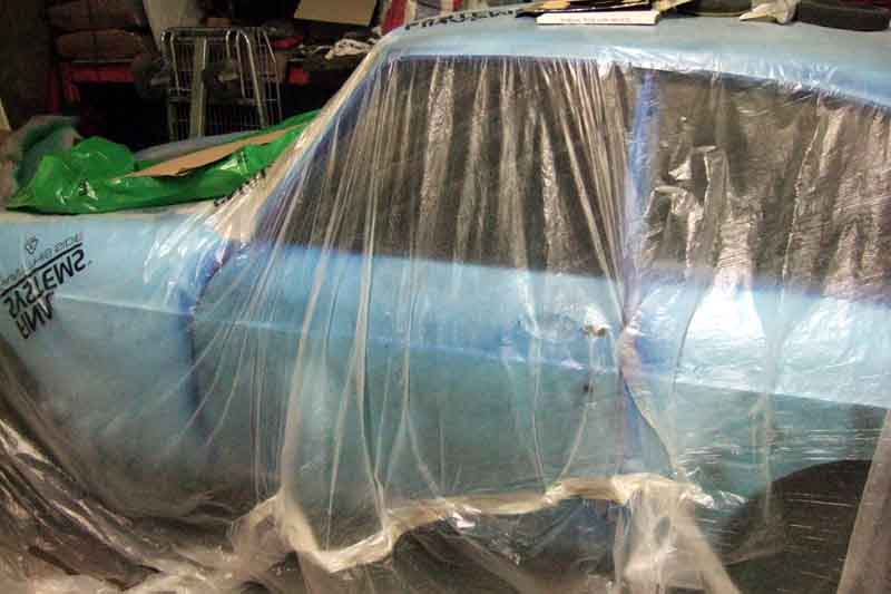
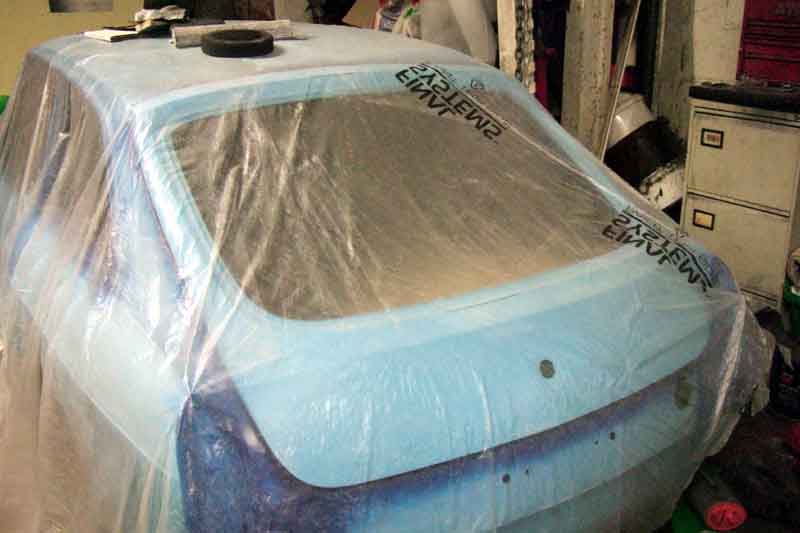
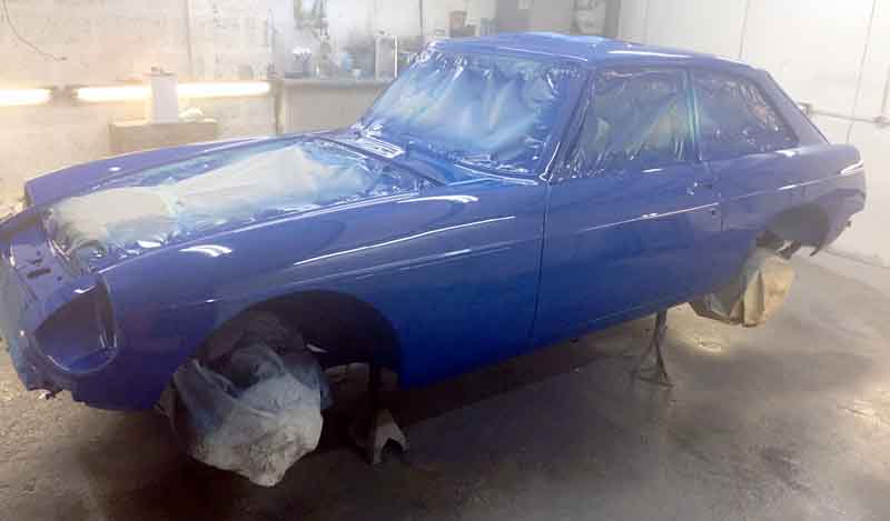
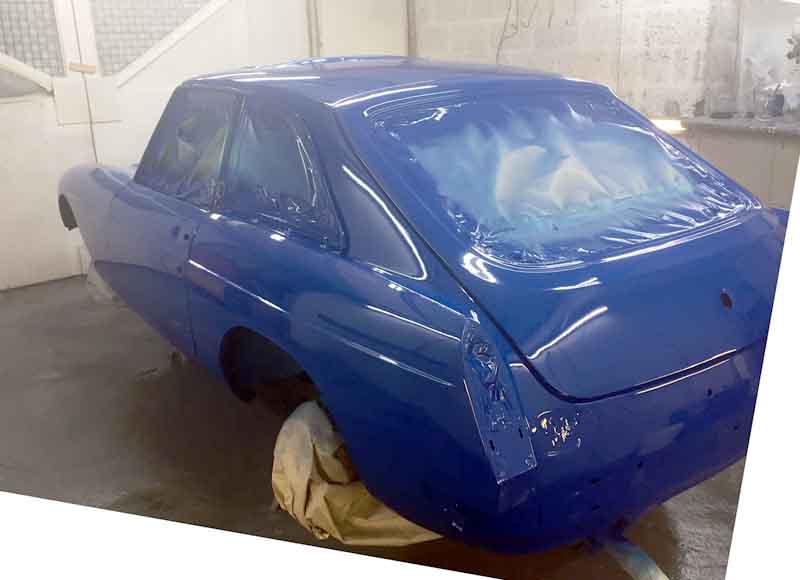
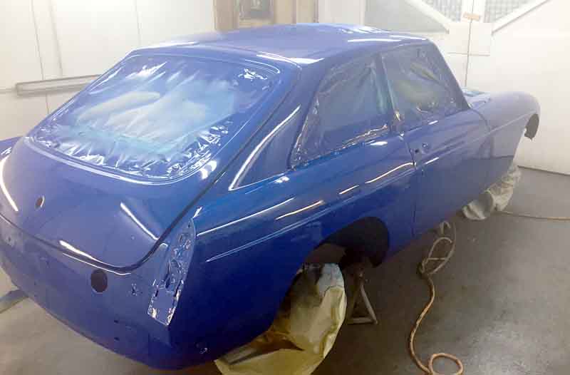
Vee at the paint shop

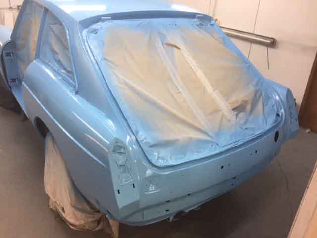
Doors and tailgate to be removed, to paint the backs and the openings
I'm now pondering stripping the rest of the stuff out of the engine bay!
Bonnet and air dam in the back, it's amazing what you can get in these cars.

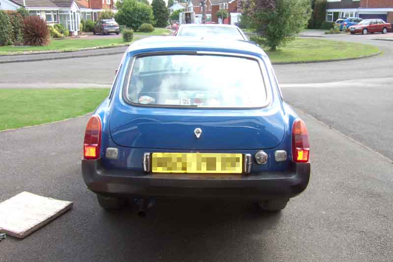
Rear valance to be replaced - at least that was the plan following a visual inspection, but on attacking it with a needle gun de-scaler only two small sections near the bumper mounting holes need to be patched.


A gap has opened up between the 'new' wing and the panel at the base of the screen, so that will have to be removed and refitted.
Wing removed again for refitting - correctly this time.
Comprehensively Waxoyled at some time in the past, painter said "That's why the body is so good". It was Waxoyled before my time, but even after 22 years, if summer sun is shining direct on the tailgate for any length of time, Waxoyl drips out of the latch aperture.
Trim parts back home, plus front and rear screens. The block and crank were back at the workshop - but hadn't been machined because they had never supplied new pistons to the machiner! In four months! You couldn't make it up.
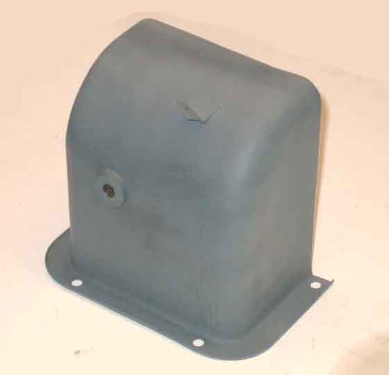
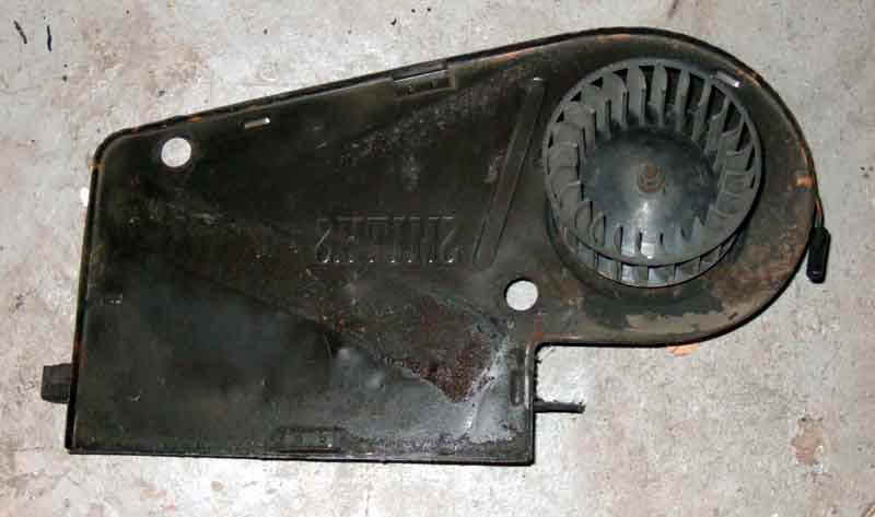
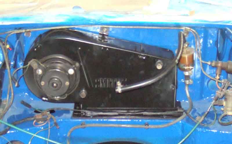
Fan guard stripped back. I thought this was going to be a pain, but with a cup brush running in line with the 'channels' that are formed by the expanding process, it all came off easily.
By contrast the smooth surface of the pedal cover took quite a bit longer to do.
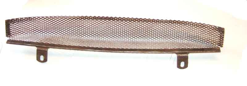
Primed
I have decided to strip the bulkhead and do a proper job on the engine bay. But first I checked I could get at and loosen all the fixings before I started in earnest. Ironically the pedal cover screws, which I had have off before, were the only ones I couldn't immediately shift, plus a harness screw under the heater motor. Fortunately the rear outer pedal cover screw i.e. the one that could only be removed by drilling out using a bit with a hex shank in a couple of 1/4" drive extensions - had not been refitted the previous time, I suspect because I couldn't clear the hole. The rear inboard screw - together with the harness screw - came undone with a battery impact gun but the others just stripped the slots. The front inboard came undone with Mole grips, but I couldn't get a purchase on the front outboard so had to resort to hammer and chisel. That lifted the head a little more, then a combination of pipe and Mole grips got it out.
All the servo and screen-washer bottle holder fasteners (one nut under the bulkhead in the cabin) were fine, which left the heater. All the screws came out OK, but would it move or was it glued in by a decomposing rubber block!? A tentative lever with a large screwdriver under the flange on the servo side and it moved, then levering it a bit more there was a sound of something coming unstuck and then it moved easily!
The three pedal frame screws into the bulkhead shelf were fine, but for some reason the top two go through from the cabin side into welded nuts on the frame - and the heads of those are well concealed by harness, steering column support structure, and sundry other bits and pieces. I could get at the outboard one with a double 3/8" wobble extension, but the only thing that would fit the inboard one was a ratchet ring spanner - but the swing was so restricted it would only move about three clicks at a time! But by removing the voltage stabiliser and two of my relays, plus the indicator flasher and its clip, I got about 15 degrees of swing, but it still required a lot of patience. I can only get finger tips to them, so refitting is likely to be problematic, so I'm pondering putting Riv-nuts in the bulkhead from the engine compartment, and using bolts through the pedal frame. Perhaps the risk of the harness chafing on the ends of the bolts is why they weren't done that way originally, so I will have to bear that in mind.
My next visit was to remove it all, which meant draining the fluids first to stop it going every where with pipes disconnected, then get the water bottle box out of the way. I couldn't initially get the pipe from the brake master to the servo undone, nor the one from the servo to the manifold on the inner wing, but the other two came undone OK (only the rear and the OS front split off here, the NS front comes off a Tee at the servo). The pipe down to the clutch slave hose bracket also came undone easily. I didn't want to undo the banjos on the back of the master at this point, which meant removing the pedal-box, servo, brake and clutch pipework as a unit! I took the pedal pivot hardware off, so the pedals would come out of the hole in the bulkhead ... once I had remembered to remove the pedal return springs! Wrapped tape round all of the pipe ends to stop dirt and paint getting in. Might as well remove the clutch slave and it's hose as well.
That left the heater, but first I removed the air direction control from the dash and disconnected the cable from it, so I could remove the cable with the heater unit. Then unscrewed the demister support pipe clips from the cabin side of the bulkhead, and pulled them back out of the rubber block. After that, as it seemed loose with all the screws removed, I just went for it and pulling and wiggling and easing the top forwards to clear the panel at the base of the screen, it lifted out very easily. Being able to stand in the engine compartment was a great help.
Next was to disconnect the battery cable from the toe-board stud, so I could remove the brown wires, and pull that tail of the main harness up out of the way. The V8 has this extra connection point, the cables don't go direct to the solenoid as on the 4-cylinder. A bit of the fiddle as the rubber boot over the battery cable lug and fixing nut had gone rock-hard and had to be cut off. Then pull the rear harness (already disconnected from the main harness) down and out of the way. Remove the fuel filter and its mounting clip. Finally pull back the choke cable, temp gauge capillary, heat control cable and screen washer pipe back into the cabin, pull out the large master-cylinder access bungs, and tuck the bonnet release cable into the cavity in the NS inner wing. And the bulkhead is clear! The painter can work round the main harness and the steering rack.
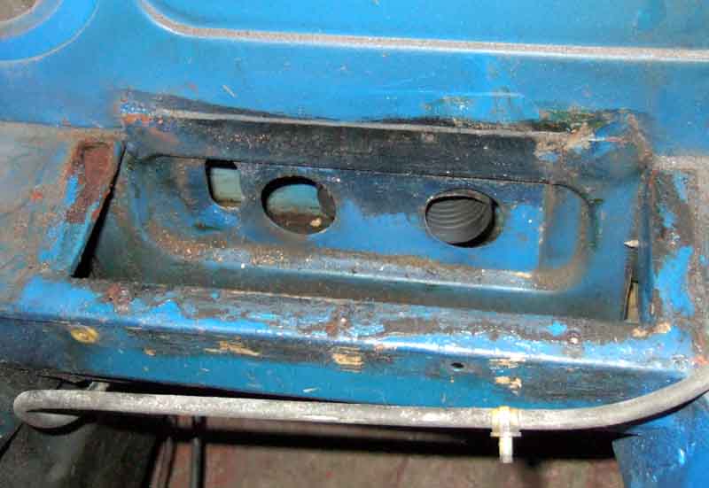
The heater aperture, showing the slot to the left which makes removing and fitting the heater with the air-direction cable already attached much easier, and the ends of the demister corrugated tubes. These just push into the rubber block, no plastic tubes connecting direct to the heater ports as originally.
All the bulkhead hardware back home ready for cleaning, painting etc.
The hidden side of the heater, with the rubber block at the bottom, and the air-direction cable to the right.
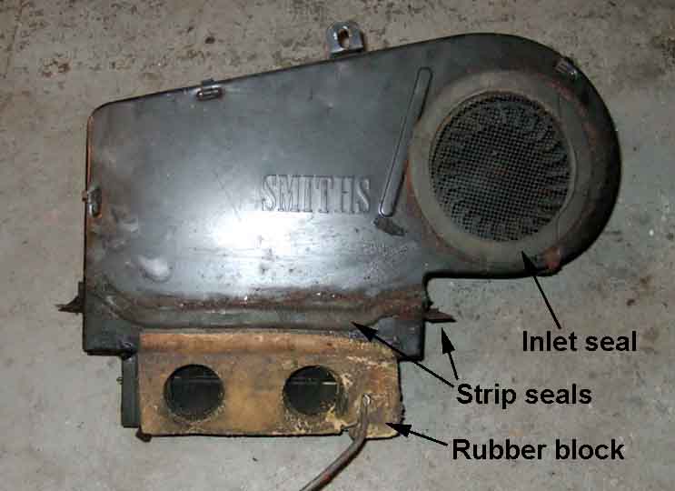
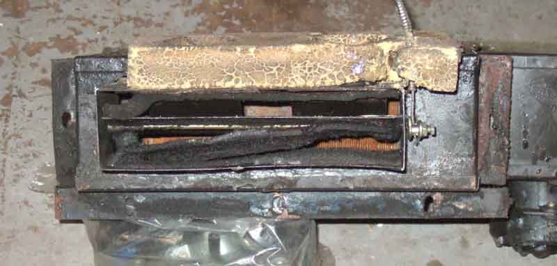
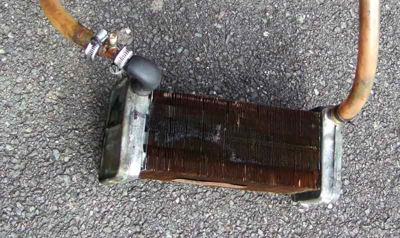
Heater cover removed, manky foam on top of the matrix ...
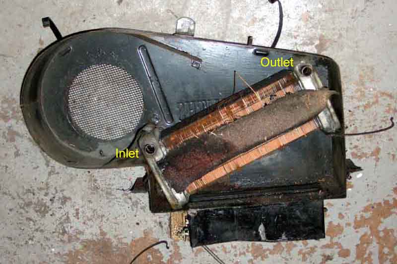
... and no foam at all on the other side ...
... just lying in the bottom. This means that a significant amount of air would have been able to bypass the matrix, reducing its output. I'm not surprised, in the past I've noticed little bits of old foam blowing out of the vents from time to time, and it's never been as effective as Bee's heater.
Back of the cover
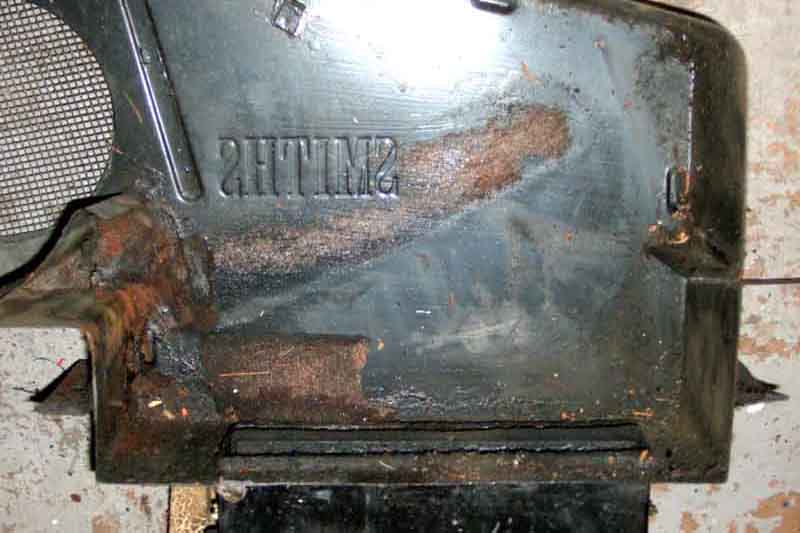
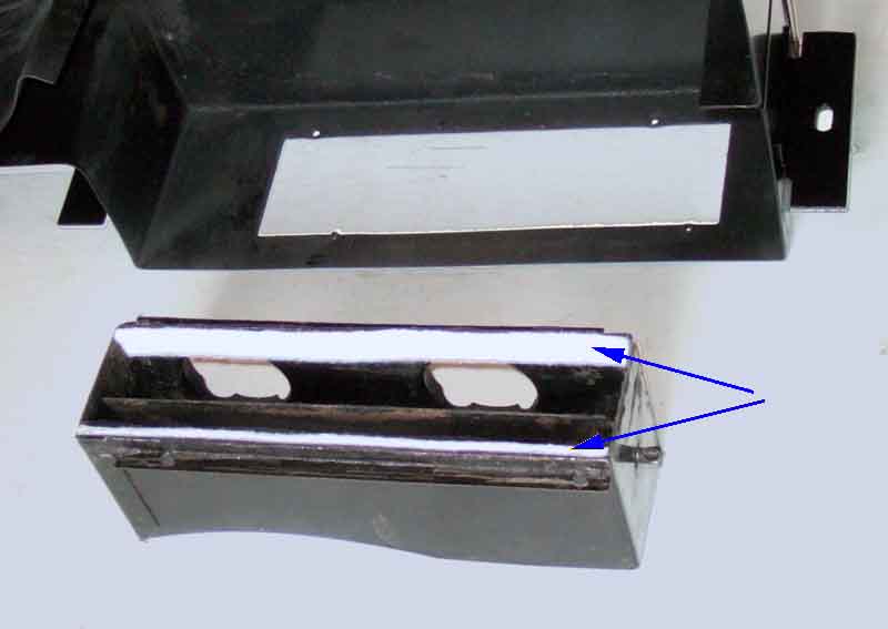
Bottom of the heater, rubber block upper-most, with the felt/foam strips coming unstuck from the flap and the surround - more reduction in performance. No less than six strips on the flap and in the channel up to 1/4" thick, seems overkill. Stranded inner on the flap, which as it has to push as well as pull (no spring return) seems strange. However given the routing it takes - out of the bulkhead then across behind the dash to the control, it is more flexible. This is manky at the flap end, with a couple of broken strands, so I'll replace it with stuff I've had for years. That's thicker, but it does go through the inner and the trunnions, and will be stronger but still flexible.
Next visit was with a pal in his BMW estate to remove everything else from the workshop i.e. dismantled engine, gearbox, and all their ancillaries. The painter said we can store the gearbox there so that went round first. Then we went through a two-page parts list ticking off everything I could see that should be there from the parts catalogue, workshop manual, photos, and anything else I could think of. They were all there, but all the nuts, screws, washers and bolts were in one of two small boxes so too many to trial fit there and then, something to be done before it goes to the machiner. Last thing was the exhaust - in a single length. Fortunately the paint shop is only a few hundred yards from the workshop so I walked it over while pal with everything else drove round to meet me. Then back home, and unload into the garage.
Plenty of scope there for cleaning and painting! Next week it's over to the machine shop with the block and crank for him to have a look at, and get an estimate of costs.
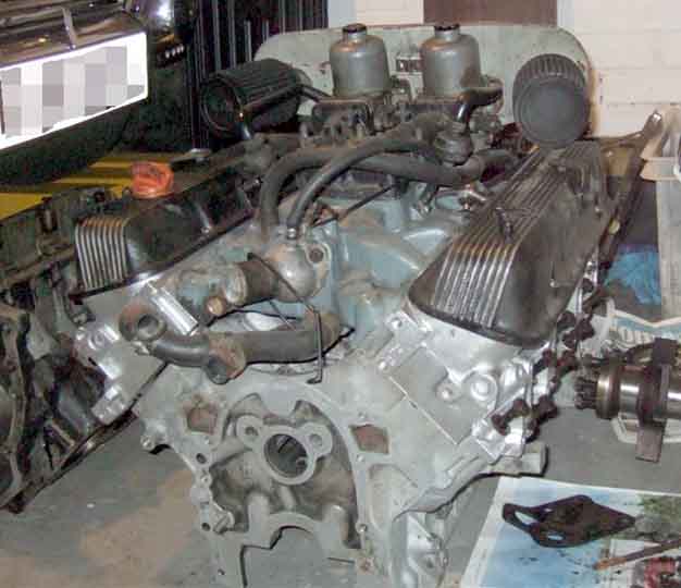
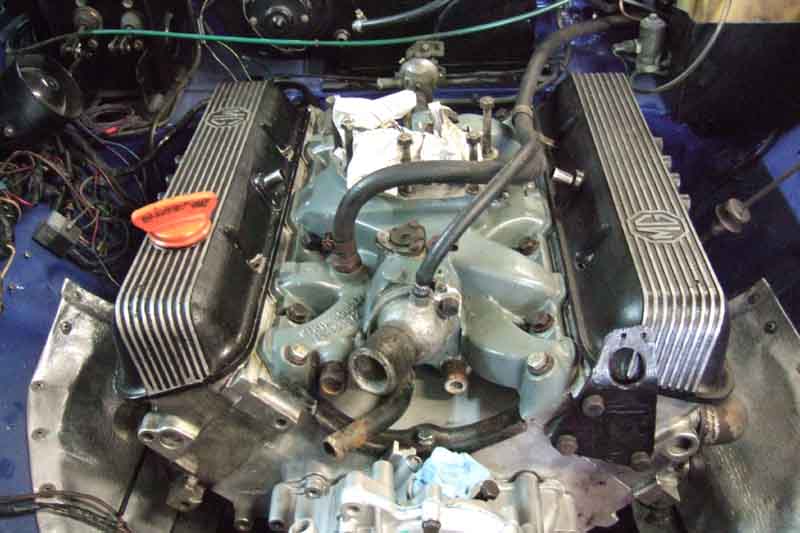
But first a dry-fit of all the parts that will go to the machiner for him to assemble, to check all the fasteners are present. (The plenum, carbs, airbox and filters are as a unit so dropped onto the inlet manifold for a bit of fun.)
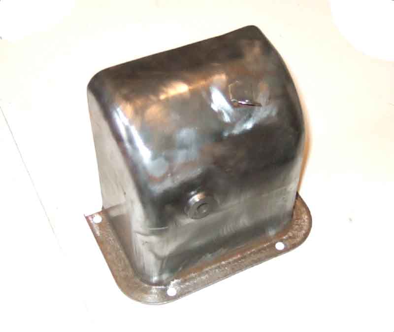
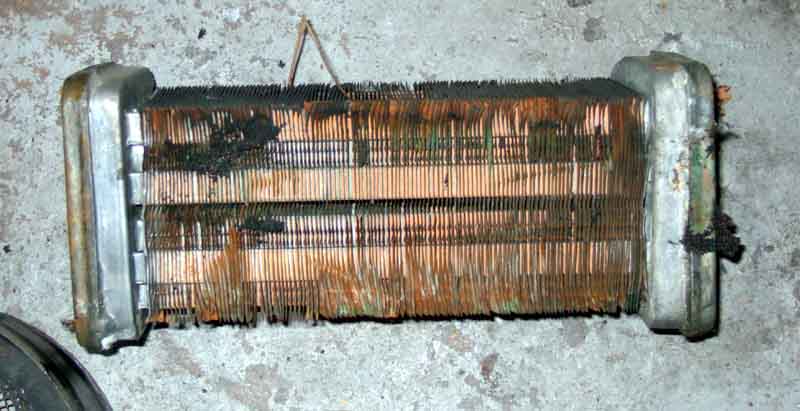
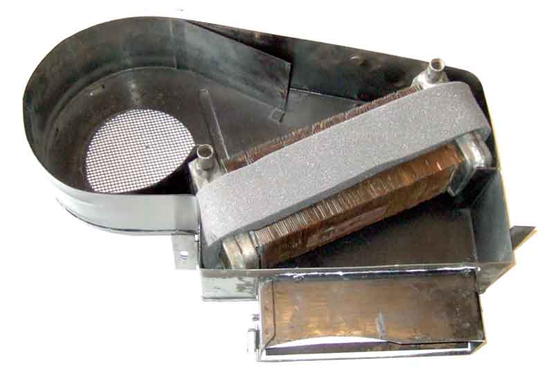
The heater casing is in quite good condition, but a rough (to the touch) area on the top proved to be very slight rusting under the paint, so the case and cover gets rubbed down to clean metal, two coats of zinc primer and two of satin black to-coat. I decide to pressure-test the matrix. In the past I'd made a Tee with a Schrader valve to insert in the small remote header tank hose to pressure-test a pals late-model system, so wrapped duct-tape round that to build up the size to fit a length of hose that would fit in the matrix spigots, and used one of the rocker-cover breather hoses on the other matrix spigot. Used my foot pump to build up some pressure to prove it was air-tight, then poured water into the matrix to a level just above the tops of the spigots, then pressurised it to 20psi. Left it overnight, still some pressure left next morning, but more importantly no water on the vinyl-topped workbench, so the matrix is fine.
The section that contains the air-direction flap is screwed to the bottom of the main case, so can be removed making cleaning and replacing the felt easier. Originally there seemed to be strips stuck to both sides of the top and bottom of the air channel, plus two or three stuck to the movable flap as well, i.e. about seven altogether. I used 3mm felt from a hobby-shop and felt (ho ho) that four pieces stuck to the channel top and bottom and both sides was thick enough to form a seal with the moveable flap at either of its extremities of movement.
By this time I'd finished painting the case and cover so screwed the air-direction section back and put the matrix in with its new foam seal. With hindsight the right hand end would have been better near the bottom of the matrix, so it was wedged between it and the case, like the other end is at the top. But it already had to be stretched to fit over the matrix, so that would have stretched it more.
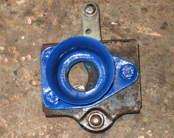
A new one on me, and very fortuitously mentioned by Ray Longsheds during a discussion about steering wheels, were these matrix port grommets (7H1993). Not on either Bee or Vee, and not in my Parts Catalogue. Seemingly stocked by all the usual suspects, but only listed for the MGA by MGOC. They finish it off nicely.
Other painting has been two satin-black top-coats on the pedal cover and fan guard, plus derusting and two coats of Hammerite satin black on the pedal frame, water bottle box, servo brackets, and rear cross-member.
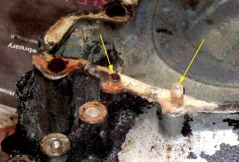
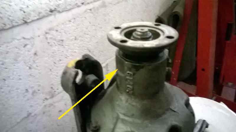
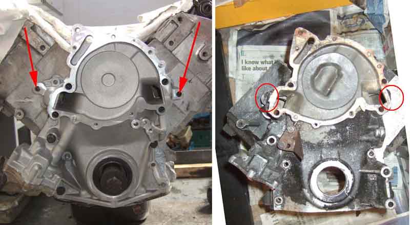
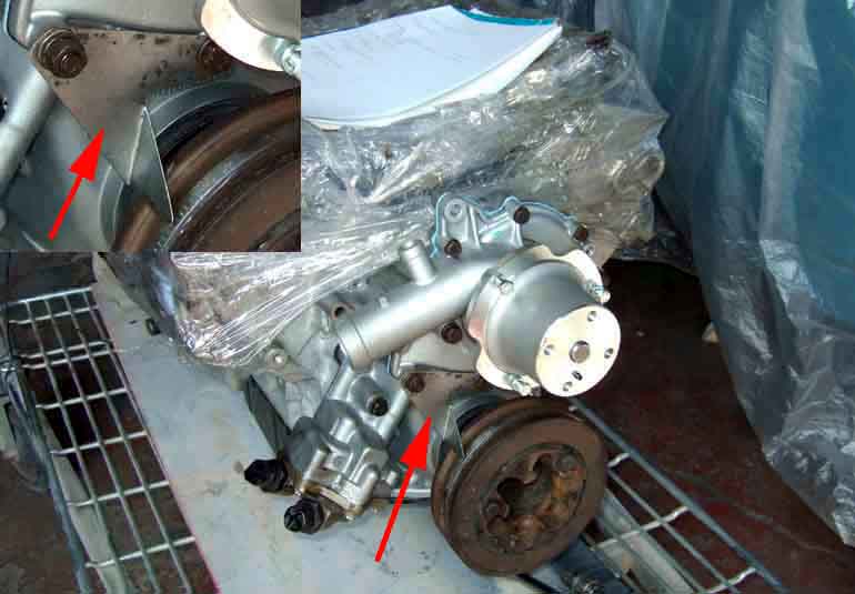
I've been puzzling over the water-pump bolts. The books say 5 1/4" bolts, but I only found four, and the fifth hole (at the top) was 5/16", so I came to the conclusion that one had stripped and been drilled and tapped to 5/16". But then while dealing with the alternator and its mountings I realised the 5/16" is for the end of the adjuster bar, which still left a missing 1/4" bolt hole. Then looking at the front cover I thought "Why would they put two dowels next to each other?" And of course they haven't, one of them (arrowed on the right) is a sheared bolt! So along with a new water pump, there'll be a new front cover (because of other issues as well as this). And because that has deeper oil pump gears I'll need new gears as well. The 12-point oil-pump cover screws were a bit of a pain. I don't know what the size is supposed to be but an 8mm socket was a better fit than a 5/16", but still a little loose. I bought a 9/32" but that was nowhere near going on. Three of the screws came out with the 8mm, but for the others I had to drill the heads - one off completely, the other two the heat and vibration from drilling meant they undid with grips.
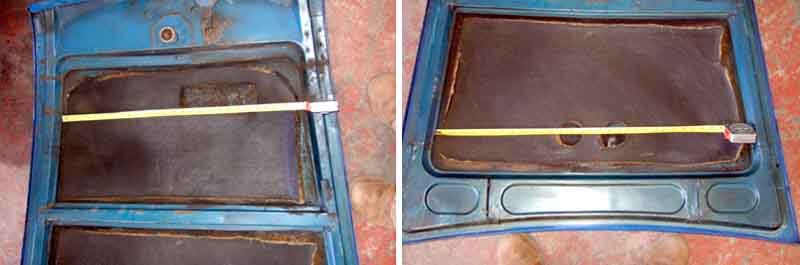
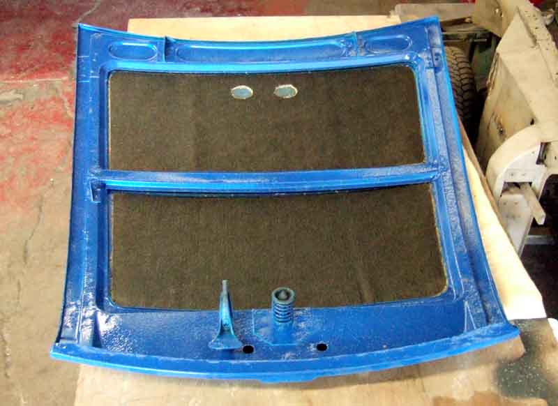
March: Stripped the old bonnet sound-deadening as it has shrunk and was very ratty, after measuring the positions of the cut-outs for the carbs and the rad. These will have to be cut in the new insulation as there are no pre-cut pieces for the V8, not even for 77 and later 4-cylinder cars with the radiator in the V8 position. I questioned the need for the cut-out for the radiator, especially whether it needs to be a large rectangle, as the filler plug is the highest part by a good 1/2" so only a small circular cut-out would be needed - if that. In the event, with rad and bonnet fitted, there is still 1/8" clearance between the top of the plug and the underside of the uncut insulation.
If it moves, lubricate it. If it doesn't, paint it. Everything that is going to be painted, painted.
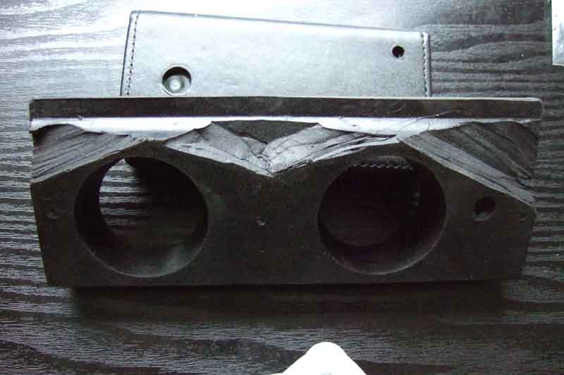
The heater block - modified to reduce how much has to be compressed to get it into the recess in the bulkhead, without reducing the holes the demister pipes push into.
Almost ready for priming, final masking-off to do
Engine bay already primed
First primer and guide-coat ready for flatting.

One side flatted, about 3 very minor imperfections to be filled.
As part of the preparations for reassembly I have been checking I had all the fasteners, obtaining replacements for those that the original people had lost, and making sure they fitted. I could not get new nuts on the propshaft bolts in the gearbox flange, jamming after about a quarter-turn, both Chris (he does mechanical restoration as well as body) and I felt that the bolt size or thread was wrong. In response to enquiries no one was aware of any oddities with these - which should be 3/8" UNF, and Roger Parker at the MGOC confirmed that the special bolts and the nuts that they have did fit each other, so in the worst scenario I could replace the bolts as well, but at Ł20 for a set! I would also have to remove the flange from the output shaft to replace them. However a pal had a 3/8" UNF die, which ran down the threads with relatively little force, and after than the nut went on easily. The die fetched out a lot of gunge, so that's all it was - gunge in the bolt threads preventing a new nut going on. The interesting bit is that as I went to put the die on the first bolt while it was still in the flange, I noticed a flat below it on the OD casing ... which allows the bolts to be removed! One lives and learns.
April: Final primer - two coats of sky-blue which should suit the Tahiti Blue top-coat better, ready for flatting and top-coat.
Tailgate is on a rack in the main workshop
Next step is to top-coat the engine bay, then I can fit that out, ready for the engine and gearbox to be reinstalled.
A moments panic over the engine as the machiner said the main bearing caps were the wrong ones for the new block. They are installed to a newly-cast block, then line-bored to take the shells, to make sure they are all exactly in line. Fit the wrong caps, or get them in the wrong positions, or the wrong way round, and it can lock the crankshaft. The machiner needs the right caps to mount it on his boring machine, to make sure the rebore is exactly in line with the crank in both fore/aft and side to side directions. Having had both my old engine complete and the new block and its caps in my possession at one point, and shipping the new ones off to the engine man, I thought I had been careful to keep the right ones with each block. However, after supplying the 'other' set, the engine man said they were the right ones - phew! Because the replacement block and caps were new to me I couldn't be sure they matched, and had they also been wrong I would have been without an engine.
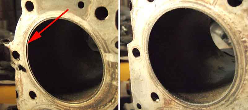
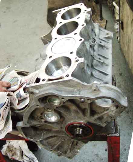
He also had a look at the old block and said it was no good as the liners were slipping, and indeed you can see that it has for No.1 cylinder on the left here, all the others are flush, as with No.3 on the right. Lit from the left clearly shows the recession:
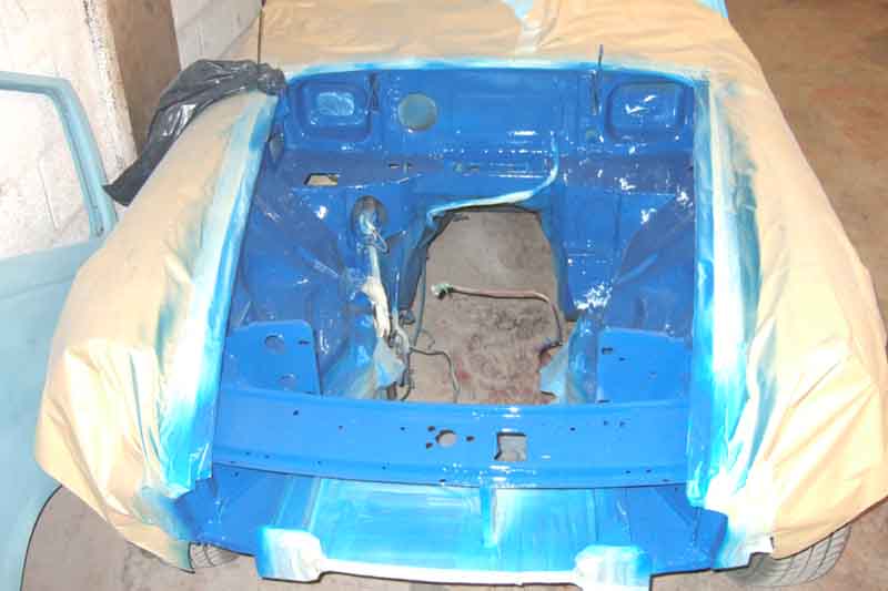
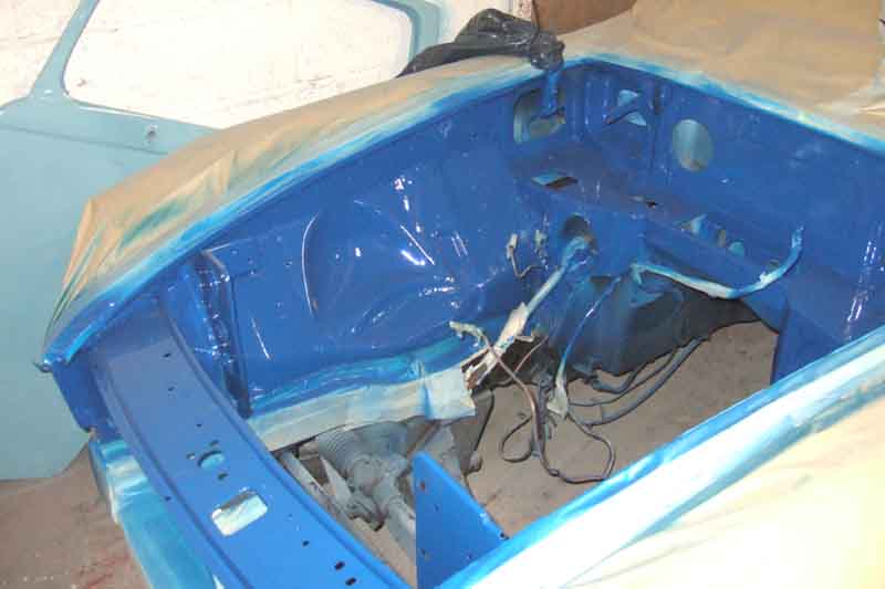
Engine-bay painted - it's very blue! Acrylic 2k in there as it is more hard-wearing - four coats. Externally it will be base coat plus clear coat to give a good finish.
Wiring fed round the front and down to the toe-board stud. Hydraulics reinstalled, clutch slave hose left loose until it can be bolted to the bell-housing to get the correct alignment.
Fuel filter, screen washer box fitted and bonnet release fed round to the front. Heater is waiting for grommets for the ports, only belatedly discovered these as neither Vee nor Bee has had them.
Heater installed ...
Wiring etc., oil gauge pipe and heat insulation ...
... attached to the inner wings.
Oil filter, pipes and cooler, cooling fans, horns etc. still to install at the front of the engine bay but I'm leaving those until after body-paint to avoid overspray.
... cam and timing gear fitted. Waiting for front cover to arrive to fit that and the sump. Some more work on the heads then they can be fitted, then transported to the paint shop.
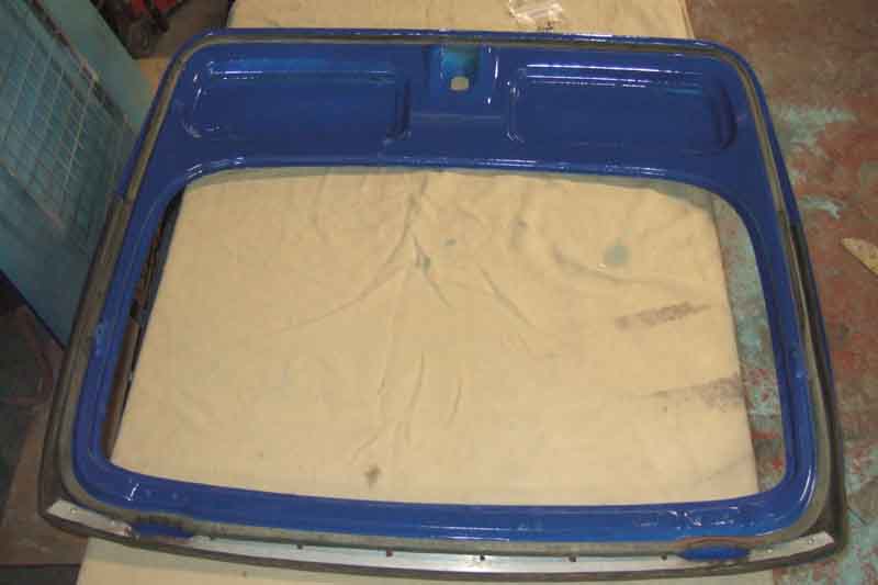
Backs of bonnet and tailgate painted ...
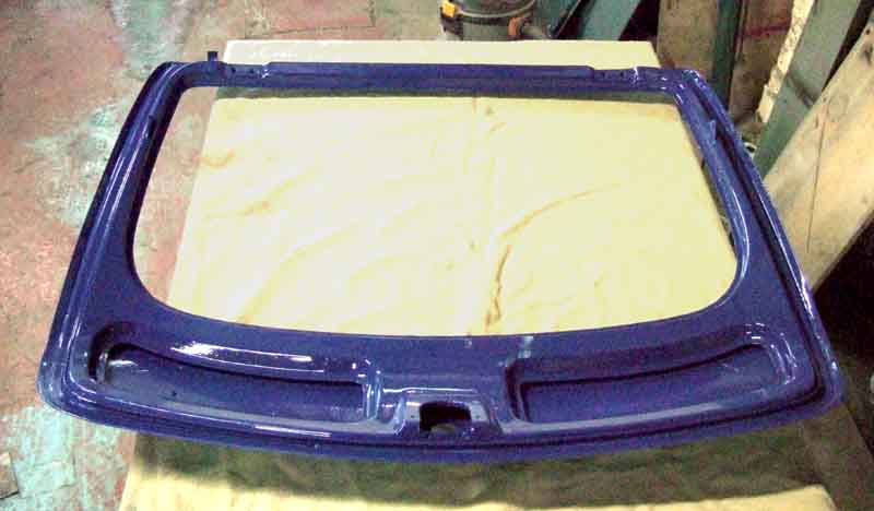
... seals fitted ...
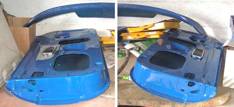
... and backs of the doors and the air dam painted.
Bonnet insulation installed - much easier upside down than when fitted as with Bee! As well as two coats of spray adhesive on the backing I ran an additional narrow strip at the edges the edges, then when laid in place wedged strips of hardboard under the reinforcement flanges to hold the edges down while they dried.
Shut lines round bonnet, doors, windows, hatch and light mounting points painted ...
... and bagged up to keep the dust out until painted.

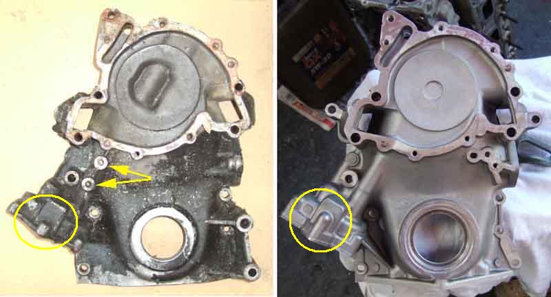
Original (left) and replacement (from Clive Wheatley, right) front/timing covers. No mounting points for the original timing pointer (arrowed) on the new cover, but Rimmers have a modified pointer (Ł45 inc P&P!) which hopefully will mount to the new cover somewhere. Deeper oil pump gears (circled) should maintain oil pressure at hot idle.
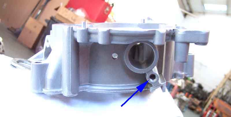
These covers also have another tapping under the distributor (arrowed, the other hole is for the distributor clamp bolt), which has to be plugged for this application - I'll be using a 3/8" x 3/4" UNC button screw. A grub screw has been mentioned but you don't want that screwing itself into the cover and hitting the timing gears. Also Clive's remanufactured water pumps have metric tappings for the pulley despite him having asked for - and got - Imperial in the past, taking an M6 x 16mm fully-threaded set screw in place of the original UNC.
Because of the delay with the engine, other projects and needing to do paying work, did mean the exterior would have to be painted prior to engine and gearbox installation - not ideal. However another project came in which gives me another couple of weeks. Although unfortunate timing means I am away for two weeks at the end of May/beginning of June, so engine ancillaries and first run won't be until after that, I'm hoping the finished engine will be delivered to the painter ready for installation by my return.
June: More delays as the engine man had some questions about valve stem seals while I was out of the country for two weeks and had lost my mobile number. Still, that is sorted now, heads skimmed, completed engine should be at the paint shop ready to be reinstalled Tuesday next week. Note the false rainbow patterns, similar to feathers and butterfly wings this is caused by very fine grooves on the surface, so fine that they refract the light like a prism, changing the colour according to the viewing angle. Some speckling from pinking/detonation on the faces inside the combustion chamber, but nothing to worry about. New valves and guides, whilst the old exhaust valves had flat faces and these have a slight dimple which would tend to lower compression ratio, the new inlet valves have a significantly shallower recess than the old ones which will more than compensate. The effect of that, the skimming and tin-shim gaskets should be interesting ...
Doors and tailgate fitted, and bagged-up until final flatting and paint.
Tuesday came and went and it was only when I phoned to ask what was happening that he informed me there was a problem with the front cover, something about bolt holes not lining up, but as usual he gabbles away, talks in half-sentences, and ends up saying "but it's up to you". So another trip over there after a night stressing about how big the problem was, only to find that there isn't a problem at all. This modified cover has two extra lugs with bolt-holes, that have nowhere to go on this block. But they have all the original bolt-holes as well, so these can simply be left. One would think he would have had enough experience to know that, but there we are.
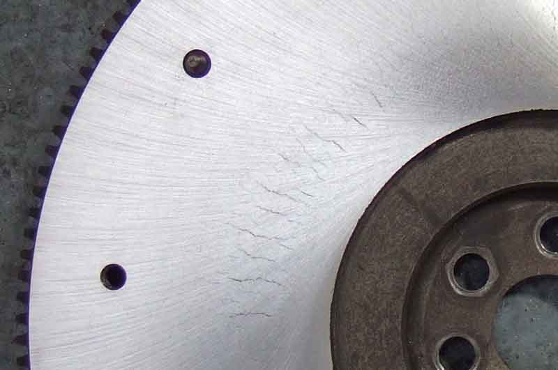
Flywheel machined ...
... he said it was pretty bad, and hasn't been able to machine all the surface cracking out.
But the engine is 'fully' (as fully as the engine man is going to do, leaving water pump and inlet manifold for me) built, so should be delivered Wednesday ... or is it Thursday? In any case I'm not available Friday, the paint shop isn't open weekends, and I'm unavailable again Weds, Thurs and Fri next week which only leaves Monday pm and Tuesday to get the flywheel and clutch back on, the gearbox attached, and get the lump in and on its mounts before the painter is on holiday for a week. His mate should be there so as long as the engine/gearbox is in I'll be able to carry on fitting-out, otherwise it'll have to wait until the painter gets back.
I can't find any way of mounting Rimmers modified timing pointer to indicate TDC, so have to fabricate my own. But with the old engine, front cover and water pump at home, I decide to best place to mount one is on two of the lower water pump bolts - one that goes right through the front cover and the other just into it. With the original pointer (which I had lost, but found again when it came back with various bits from the engine man this week) I was able to make a card template, and from that cut one out of sheet metal. With the pulley (which I now have back as well) in the front cover I turn that so the original pointer is over the TDC mark ...
... then remove that and fit the new one, for final tweaking of bolt holes and pointer angle to be in the same position. I say 'in the same position' but here it's actually a bit less than one degree retarded, pending final tweaking once on the correct rebuilt engine. Not that the original is that accurate, it is adjustable which on the face of it may be to cope with different-sized pulleys, but from the normal viewing position it makes a significant difference to timing as well - about 7 degrees! However exact timing is less of an issue with low compression engines, and this is a 9.35 block with standard 8.25 pistons, lightly skimmed heads, and the exhaust valves being almost flat rather than dished as per the originals, so what the final comp ratio will be is anyone's guess. I'll be conservative to start with, and think about ideal timing when I know it runs as it should!

At last the engine reaches the body shop!
Flywheel fitting ...
... and clutch. I bought a smaller alignment tool as the 4-cylinder one didn't fit the spare crankshaft I had at home, Vee's being with the engine man. But it turned out to be way too small, and I hadn't taken the bigger one. Body man had a set, none the right size, but padding the next size down with tape got the friction plate approximately right, then peering into the splines with a torch and comparing the edges of those with the pilot bearing one small tweak to get it to where I thought it was right, and a trial fit proved it OK.
Water pump fitted, with my fabricated pointer.
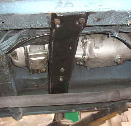
Engine mounts fitted. Only discovered then that the upper bolt had sheared off in the block, so flush it was almost invisible. The mounts were the only things I didn't trial-fit to the block. But using the mount plate - held by the lower bolt as a guide - I drilled and retapped. Also found one of the block drain taps damaged, but I had taken a couple of spares taken from the old block and another I had and replacement only took moments, although the off-side one tripped me up later on.
Then an opportunity to experiment with the crossmember and find the best way to attach it to the angled studs on the rubber mounts, and also which-way round everything goes - there are 32 combinations, and only one is right!

Gearbox fitted and ready to install. However big problem with the release bearing - it wouldn't fit as it was a completely different design! Details here, I had to reuse the old one.
It was only after looking at these pictures I realised the engine mounting plates were on the wrong sides, despite what I thought was careful consideration beforehand. They are handed, fit either side, but make a fore and aft difference in the position of the engine by about an inch. Vee came to me with them on the wrong sides, only discovered when the sump wore through from rubbing on the front crossmember. Changing them over at that time with the engine in-situ was challenging! Next day I confirmed they were on the wrong sides, so swapped them over. You also have to be careful to get the chassis studs in the lower of the two possible positions. Getting ready for installation, rear of the car raised on the lift.
Half-way in, and we find that the legs of the ramp hit the wheels before the engine has gone in far enough. So careful co-ordination of ramp and hoist was needed to lower the car and slide the front arms under the body, then lift the whole car until the hoist legs would go under the wheels.
After that it was a matter of inching it down and back, raising the gearbox to get it over the fixed crossmember, and lowering it into position. A final bit of wiggling and levering drops first one, then the other, mount studs into the chassis brackets, as it's not possible to lower it straight down into both at the same time. At least one of the mounts has what looks like two factory spacer plates between the mount and the engine bracket, but on the off-side there was also a circular slotted spacer between the mount and the chassis bracket, which I replaced with a thicker one, to try and stop the exhaust manifold hitting the inner wing that side. In hindsight it would have been better to remove the 'factory' plates, which would have brought the studs closer together and made it easier to drop into the chassis bracket slots, and fit another circular spacer afterwards. But there we are. These engine mounts are tricky, they have to be high enough so the studs don't sit in the bottom of the chassis brackets slots which would put the mounts in shear instead of compression, but not so high that you can't get the locating plates under the chassis brackets the right way round. More info on mounting bracket, mount, and locating plate orientation here.
Crossmember installed. It's said that there are at least 16 ways of installing the crossmember, and maybe 32! However careful consideration can eliminate most if not all of these. The first is which way round the crossmember goes, but whilst there are several different types there is enough information in the WSM to get that bit right. Next the bracket that holds the central pin and is attached to the gearbox under the rubber mounts can go either way round. These hadn't been removed on mine, and as everything aligned correctly beforehand I assumed they were correct, and I didn't note which way round it was. Next the bracket under the pin can twist on the pin to go either way round, which changes the fore and aft position of the welded nuts in the bracket under the pin relative to the crossmember, and finally there are two holes each side in the angled brackets on the crossmember for the mount studs to fit into, which changes the fore and aft position of the crossmember relative to the gearbox. Testing the various options before the gearbox had been attached to the engine showed that the only way that the crossmember could be attached to the gearbox so everything lined up was if the welded nuts in the bracket under the pin were virtually in line with the studs on the rubber mounts, and those studs went in the front holes in the angled brackets on the crossmember. Whether that then lined up the crossmember with the correct holes in the chassis rails was another matter! Getting the mount studs in the holes in the crossmember was the next challenge. Some have slotted them, slackening the mount to gearbox bolts made it easier, but then retightening the mount to gearbox bolts was not possible. In the end I found that with one side hooked over its stud, the other side popped in given a hearty upwards shove of the crossmember. Of course it went in the wrong hole, but a firm pull downwards got it off again, and another shove got the stud in the right hole. Time to check how the crossmember to chassis rail holes lined up ... and it was in the original position. All made much easier by standing under the car on a ramp. This is all for the V8 of course, other gearboxes may vary.
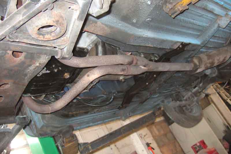
Exhaust fitted. The manifolds were the usual struggle, not helped by me forgetting to fit the dipstick tube beforehand! However eventually they went on, and again on the ramp and with the help of a transmission jack supporting the full-length exhaust it all went together quite easily. One 'gotcha' concerned the block coolant drains. I'd always been aware that there was a tap on the near-side, but a bolt on the off-side. When stripping the old block I had tried to et the bolt out, but it just wouldn't shift, even with a hammer and chisel. The flats were already badly damaged so I presume a PO had tried and failed as well. My old spare block, and the new one, came with taps both sides, so taps it was. But when I came to fit the off-side manifold it simply wouldn't fit up against the head, because one of the arms of the tap was in the way. Fortunately it came out, and I hacksawed the end off that carried the arms. In hindsight perhaps I should have just cut the arms off, leaving something to grip in case it needed tightening.
The inlet manifold gasket was a pain. The WSM says they are marked 'FRONT' and one of the bolt holes near the front on the right (off-side) is 'open' i.e. slotted. The new gasket has neither, also there are sealing rings round all the holes on one side of the gasket only, and it is flat so not obvious which way up it goes let alone which way round. I ring the supplier and he doesn't know, so he rings his supplier who says the sealing rings face downwards i.e. into the heads. Fine. However when I compare it with an old tin gasket, I realise that it can only go up one way, as the right bank is offset relative to the rear, and that puts the sealing rings uppermost! Still no info regarding which way round it goes, but careful comparison indicates that the two ends are identical, so it doesn't matter. Old tin gasket, with circles round two bolt-holes only one of which is 'open', and arrows where each bank is offset relative to the other.
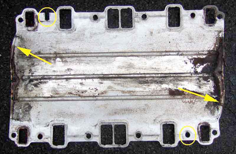
New gasket, no 'open' hole, the same offset. Although this means the sealing rings are always upwards, it doesn't seem to matter which way round the gasket goes on.
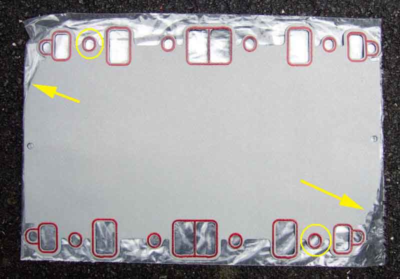
Then the WSM says 'fit the gaskets but do not tighten the clamp bolts until after tightening the manifold bolts". The gasket clamps are either end of the crankcase, between the two sets of ports, and are metal brackets that press the gasket down onto a rubber seal that fits onto the crankcase. However after suffering a persistent oil leak from the right rear corner that someone said was from this gasket, and is very common, it occurred to me that it could be because those clamps are only tightened after the manifold bolts. The holes in the gasket are larger than the bolts, so there is 'wiggle room' of the gasket relative to the heads and manifold. The gasket is also flat, and springy, so when then the manifold bolts are loose the gasket is trying to push upwards in the middle, i.e. away from the crankcase and rubber seal at either end. If you tighten the manifold bolts first it clamps the gasket in position, so when you tighten the clamp bolts it is trying to pull the gasket down, but it won't go. So I reckoned that if I fitted the gasket using one manifold bolt at each corner first to position it, then fitted the gasket clamps but didn't tighten the bolts, that would hold the gasket in the right position while I removed the four bolts, dropped the manifold on, fitted each manifold bolt again not tightened. Then I could tighten the clamp bolts to pull the gasket right down onto the crankcase, and only then tighten the manifold bolts. What with silicone sealant (not something I would normally use but felt probably better here than non-setting) on the crankcase edge and on top of the rubber seal, and sealing compound round each port of the heads and the inlet manifold, it was all a bit of a palaver.
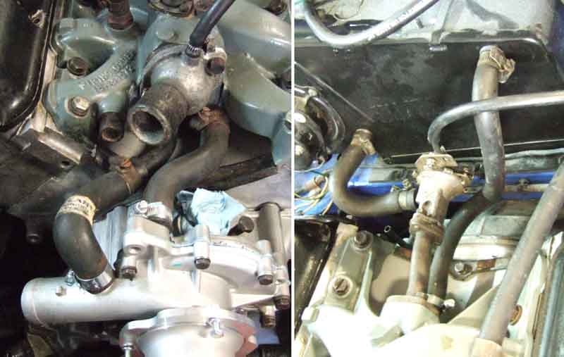
Water pump and heater hoses fitted, and heat valve cable.
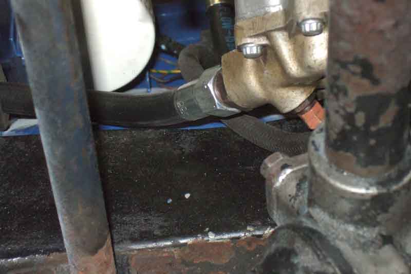
Oil filter and hoses fitted. This front cover has deeper oil gears, so the pump cover is lower relative to the chassis rail. The hoses come off the cover over the chassis rail, and after seeing a roadster conversion where someone had ground away the lip on the chassis rail at that point I wondered if I would have to do the same. Asked on one of the fora and was told by someone with the same arrangement that he hadn't found it necessary.
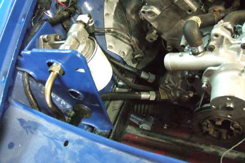
However the clearance on the front hose is very small, about 1/8", and the gauge hose is close too. Give the amount I know the engine has rocked in the past with the exhaust manifolds hitting the inner wings, I think it is too small. Rather than grinding and welding straight off, I think I'll try battering the lip over first, to present a smooth face as well as being lower.
Cooler fitted.
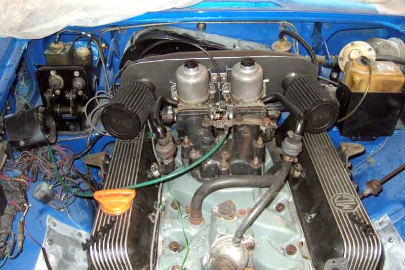
Carbs installed with all plumbing including crankcase breather and controls
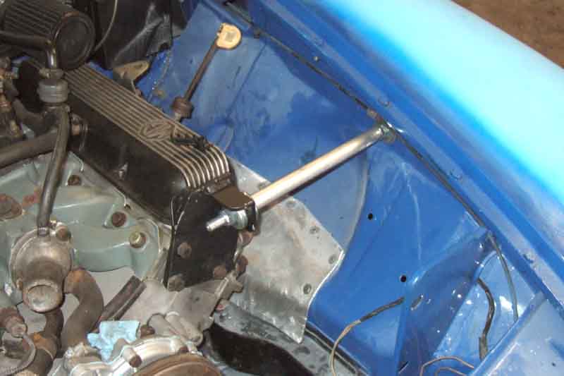
Clive Wheatley engine steady bar. Battering the chassis rail lip over gave me enough clearance to insert the end of a forefinger, and that together with the steady bar should be enough. Bar installation needed some thought to get the engine bracket holes to line up with the head. There are rear shackle rubber mount rubbers between a pair of cup-washers, and a set of those both sides of the engine bracket and both sides of the inner wing and strengthening plate under the wing. There are also adjuster nuts on the inner-wing end of the bar, which should initially be screwed all the way onto the bar. Tighten the engine bracket nut using a spanner on the inner adjuster nut, to compress the rubber bushes that end so that the slightly smaller cup-washers fit inside the larger ones. Then tighten the nut under the wing to compress the bushes that end, which will pull the engine bracket across the end face of the head. Keep tightening the nuts until the holes in the engine bracket have come past the holes in the head. Then tighten the adjuster nuts onto the wing to compress those bushes more, until the engine bracket has moved far enough back across the face of the head for the holes to line up, and insert the bolts - including the engine lifting bracket on the inside so it doesn't get lost - and tighten the adjuster locknut. This ensures the engine is sitting in its 'natural' position, and not pulled or pushed to one side by the steady bar. Of course if you find you need more clearance one side, then that can be set with the adjuster nuts.
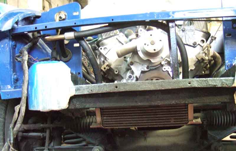
Alternator, fan-belt, radiator, expansion tank and hoses installed. I must say after nine months of seeing an empty engine bay and having had so many problems with the first workshop and two engine rebuilders I had been despairing that it would ever come together. Seeing what is virtually a fully-equipped engine bay now gave me quite a lift.
July: Then back at home I wondered if I would have to remove the radiator again to fit the cooling fans, as it is impossible to remove the blades from the spindles ... and I did. Refitted the rad and fitted the coil. Threw in 5L of Millers running-in oil, primed the oil system with my tool in a drill. I thought I could feel the additional load on the drill which indicates it had primed, but by the time I had pulled off the drill and got to look at the oil gauge nothing was showing. So next time did it for longer, and this time it was showing. Next to fit the distributor, which was a real struggle. These are always tricky as the distributor engages with a spiral gear on the end of the camshaft first, which rotates the rotor arm slightly, before it engages with the oil pump shaft. This engagement is a tongue and slot, so has to be exact, but once the distributor is in that far you can't turn the shaft like you can on a 4-cylinder, and neither can you turn the oil pump shaft. So as well as putting the engine at TDC on the compression stroke of No.1, and orientating the distributor body correctly (clips in a line fore and aft), with the vacuum capsule pointing to the right as you look at it, and the rotor pointing at the cut-out in the body for the cap location, you have to twist the oil pump shaft to the correct position. The only way to do that is to initially insert the distributor until it stops about 1/4" from fully seated, note the rotor position, remove the distributor again, move the rotor back to the noted position, then look underneath the distributor at the tongue on the bottom of the shaft, note it's angle, and position the slot in the oil pump shaft accordingly. Try again, and if it baulks again remove and alter the position of the oil pump shaft a smidgen, try again, and repeat.
That's bad enough, but the distributor was a bit stiff in the front cover - something else I'd failed to trial-fit. With the inning and outing, and twisting it back and fore to pull it out and push it in, it was getting stiffer and stiffer. Eventually it had to be levered out with a pry-bar, and inspection showed the thicker part at the bottom of the distributor shaft body, and the corresponding part inside the front cover, both being alloy, were getting roughed-up and locking together. Not enough clearance in the new cover, but I probably should have greased it anyway. So I had to file the roughness off the distributor body, and file round the rest of that part to reduce its diameter slightly, greased, and tried again. Better, but still stiff, so out again to show the witness marks on both the upper and lower parts of the shaft, and file those. Eventually it went in and out OK, so then it was down to small adjustments in the position of the oil pump shaft, until it went in!
Next the distributor clamp, and more problems. I've mislaid the original somewhere although I know I got it back from the original workshop as I ticked it off on the list. Got a 2nd-hand one off eBay ... which didn't fit. As well as the clamp not lining up with the bolt hole in the cover because there was a protrusion on the cover in the way, the hole for the bolt was significantly further out along the clamp than the hole in the front cover. So first job was to grind off part of the shoulder on the clamp to overcome the first problem which was easy enough, then I had to file out the hole so the bolt holes lined up. Over 1/4" with a small rat-tail file in steel about 1/8" thick took some effort, and the whole job took a good couple of hours. The back of the original cover is flat, and comparing a picture of the new cover with the old the centres of the two holes should be at 41mm whereas they are at 34mm.
Next fit new spark plugs ... and yet more problems. This era of V8 heads have short-reach plugs in a recess which covers the hex. When I first got Vee I found my 1/2" drive spark-plug socket would not fit in the recesses, but found another one at Halfords which was a slightly smaller external diameter and just fitted all the plugs. But that only just fits one of the new heads, and binds, and doesn't fit the other head at all. Fortunately I have my box-type plug spanner and tommy-bar still in the car, which I had modified to fit after rethreading one of the spark plugs resulted in it being canted over slightly, and meant my socket no longer fitted. Using that I was careful not to overtighten, and fitted the distributor cap and leads. Filled the cooling system - just water at this stage ... then really there was nothing to go for except engine-start.
Reconnected the battery after unplugging the alt in case of problems. Before connecting the earth lead I turned the cut-off switch on, so I could tap the earth clamp on the post to see what kind of a spark I was getting, in case of shorts. A larger spark than I was expecting, the usual squawk from the alarm system, then I became aware that the engine was cranking! Removed the clamp, pulled the solenoid wire off the starter relay and tried again, but it still cranked. Pulled the operate wire off the solenoid (which meant removing the heat-shield), and this time no crank, so somewhere that operate wire has shorted to one of the brown wires. Ponder that later, so in the meantime use one of my test wires with a croc-clip at either end to connect relay to solenoid, and turning the key cranks as it should.
However I now note there is no ignition warning light or fuel gauge. Check there is power on the white from the ignition switch ... and suddenly realise I had unplugged the alternator - Doh 1. Plugged that back in, and warning light. Still no gauge, but I know that is because the rear (and gearbox) harnesses have not been reconnected to the main harness yet. Next, no fuel pump. Not been used for many months, so possibly points. Checked power was reaching the pump, took the end-cap off (fortunately easy on an RB being in the boot), flicked the points but nothing. Tested for voltage on both sides of the points and coil, and also found it on the pump body. Then realised with the number -plate removed there was no earth - Doh 2! Jury-rigged a temporary earth, switched on, and pump action. Slowed and stopped, and no signs of dripping, so plumbing and float valves OK.
Now there really is nothing to do except go for a start. Choke out and cranked for a few seconds, but nothing. Then I remembered that years ago I had noted that the distributor was installed one position out clockwise, but I had installed this time as per the manual. So wound the engine round to TDC on No.1 compression stroke again, took the cap off, and sure enough the rotor was pointing at the wrong plug lead, so moved them all round one. Cranked again, and this time after just a few seconds it burst into life. Oddly not an exhilarating moment, just completely calm. Just a couple of seconds of slight rattling as the hydraulic lifters charged up, then it sounded lovely. A quick check round and underneath in case of fluid leaks, but all OK. Quite a bit of smoke off the exhaust which is to be expected. Then it was a case of warming it up, and continuing to look over, under and round for things that should be there. As it warmed and the stat opened I became aware of a slight bubbling and weepage from the gasket under the thermostatic fan switch, which is odd as that hasn't been touched, probably dried out over the past nine months. What was more concerning was signs of coolant around the second inlet manifold bolt from the front on the alternator side. That bolt didn't torque up as well as the others, using a bendy-bar it went up so far and seemed to stop, so I left it at that, hoping the adjacent two bolts would do their stuff, together with the sealing rings on top of the gasket and the Wellseal I had used both sides. Unfortunately this is to one side of the water passage. It's a slight seep, disappointing but again just completely calm and not thrown into a panic, I'll ponder possible solutions later.
Next day filled/bled the clutch using my method of doing it from the bottom i.e. reverse bleeding with my EeziBleed. Slave disconnected and hanging down, which makes it easier as the bleed nipple points upwards on these, front of the car raised. The seal in the EeziBleed reservoir went soft years ago which means tightening the cap down too hard it pops out of position so air leaks out flattening the tyre very quickly. Not overtightening also leaks, so I had to reinflate the tyre a couple of times. As soon as fluid is visible in the master I stop and top-off as normal. Slave bolted back up, and I'm aware that the push-rod is not pushing the piston back very far at all, and I think I can see wear marks on the push-rod from the end-cap of the slave, about half-an-inch out from where it is now. Pull off the old release arm gaiter (which is nothing more than a ring) and peer inside with a torch, but apart from the release bearing going back and fore more than I would expect it seems to be correctly retained. Fitted the new gaiter and re-attached the slave. Pedal feels OK - I half expected the piston to be pushed out of the end of the cylinder, so start the engine, depress the clutch, and tentatively select reverse - in total silence, which is more than it ever did before. Test the biting point and it's about mid-way as it should be - phew! I had visions of the engine having to come out again, although as long as the rest of the clutch worked as it should then extending the push-rod would have been the only thing that might have been required.
Next the brakes. Longest run first - near-side rear, takes several re-inflations of the tyre to start to get fluid through and no more bubbles. Off-side rear next, fluid with no bubbles pretty quickly, as with off-side front and near-side front. Pedal doesn't feel bad with the usual 'long but pumps up' showing there is still air in there, so recruit the painter's mate to press down hard on the pedal while I rapidly open and shut each caliper nipple in turn. After that it is better, but still feels a bit long, so I wedge it down over-night. That's all I can do, so pack up my tools and head for home. Since engine going in Monday afternoon last week, I've spent five half days over there, so not bad going considering the trial and error re-installing the crossmember, starter wire problem, and distributor problems. Now it's over to the painter to do his stuff, before shipping her home.
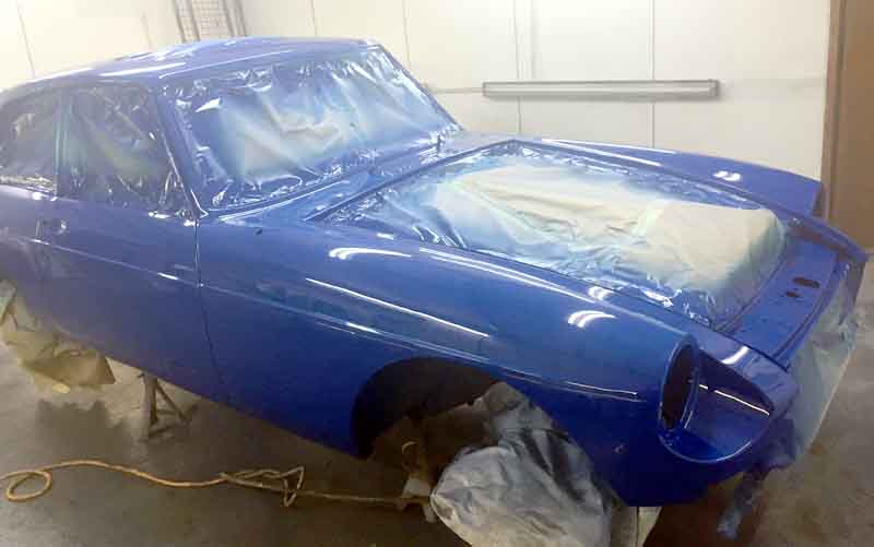
Mid-July she gets five colour coats and four clear lacquer coats. Darker than true colour from having been taken in the workshop.
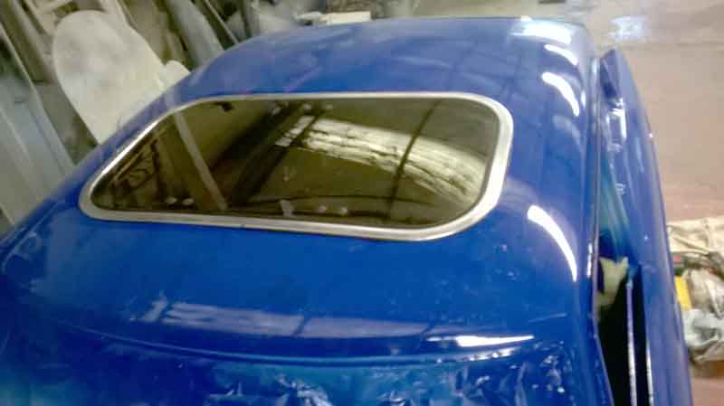
August: Sunroof fitted to give support for flatting and mopping the roof
Bonnet fitted, flatted and polished, just waiting to go on the trailer to come back home.
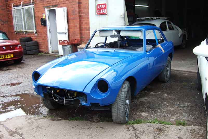
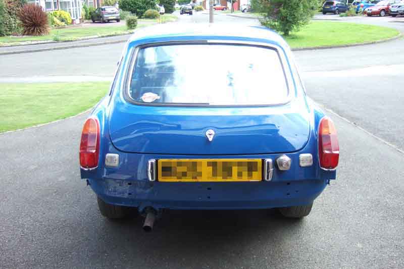
Those wheels and tail-pipe trim really will have to go!
10 months and two weeks after going away, and a lot of trauma. Very annoying when backing her into the garage to find she had dropped oil all the way up the drive, seeping from the oil pump cover. I'd previously run her for twenty minutes or so on two occasions in the paint shop with no sign of this, not an auspicious return! The one screw I could get to at that time was barely finger-tight, and the leak seemed to stop with that tightened, but what about the others? First job next day was to pull the rack and investigate all the screws. There are six - five short grey ones and one long black one, and all the grey ones were slack. I decided to remove them all and re-insert with thread-lock if I was going to have any confidence against future leaks, and immediately noticed all the grey ones had what looked like a grey plastic washer under the head, which appeared to have extruded into the gap between the shank of the screws and the sides of the holes in the cover - hardly surprising they had lost torque! I didn't notice them when I bought them, the long black (tight, remember) one didn't have it, so I removed them all. used thread-lock, and refitted. Torque is a pain - being variously given as 13 ft lb in the GT V8 WSM supplement, but 3 or 9 in other manuals. Previously they didn't want to go as far as 13 so I stopped at 10, but this time only went to 9.

Next job was to fit the front valance, which I had foolishly not trial-fitted before paint, and some fettling was needed, but performed without damaging anything. Those two jobs were pretty tiring on a warm day in full sun, so something a bit more restful for the rest of the day.
And that was to fit the door seals (to stop braining myself on the body flange), and because the doors had been wired shut for transit, the latches and striker plates so the doors don't swing open when exiting and entering the garage, and the external handles and locks.
Then the gutter trim and the rear windows and trim. Just the passengers rear window to fit at the end of day 1.
Day 2 was to fit the rear window seal - which was another strenuous job as it appears to be several inches too long to fit in the hole! More info here
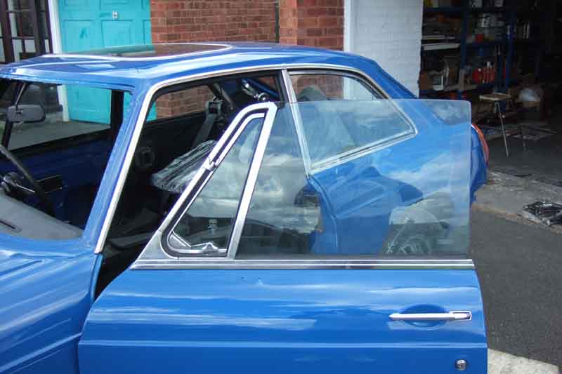
For more 'light' relief - fitting the quarter-lights. Got the first one in before I realised the external seal and support strip goes under the quarter-light on GTs, unlike roadsters where it can be fitted afterwards, so off it came again. As the nuts pull it down, and the bolts pull it forwards, tighten one too much before the other and it won't go fully down and fully forwards. I opted to push the frame firmly forwards while tightening the nuts, then tighten the bolts. You also need to make sure the holes in the seal support line up with those in the door skin, put one pop-rivet in first, doing the rest later. Finally with the door shut - carefully to make sure it doesn't foul the gutter trim - adjust and tighten the bracket to the door and the leg to the bracket, so the top of the quarter-light just touches the door seal and doesn't compress it too much. The fit the rest of the seal support pop-rivets. I find 3.2mm are slightly too small, and pull out of the door panel, but have a packet of backing washers left over from when I fitted the side trim to Bee 27 years ago, which solve that problem.
A sudden shower means I have to rush the car into the garage. I've had to leave the rear drop-glass channels for the moment until I finish off the pop-riveting, as the rear one cannot be done (with my riveter) with it in-situ. I ran out, and have ordered some more the next size up - and some of the original size in case the larger ones are too big! With those in I can fit the drop-glasses and regulators. As you can see Waxoyl being utilised wherever anything sits against paintwork - I've had this can since I restored Bee 27 years ago, plus copper-grease on all threads, and Vaseline on electrical connections.
The paint shop had fitted the bonnet prop the wrong way round (release catch at the rear) so that was corrected, and I fitted the bar for the safety catch and the main latch to the slam-panel. Try as I may I could not get the return-spring for the latter attached so the latch had to come off again for the spring to be attached first. Then I found I could not get the latch far enough forwards or to the right so the spring went neatly into the cup without scraping. This was because as previously fitted what should have been a flat panel on the latch had deformed into the over-size slam-panel holes, which limited the adjustment. So it had to come off again, and the three holes in the latch clamped into a vice to flatten them, which has damaged the paint, but after that I could get the correct adjustment. But I intentionally had the slam panel painted without this fitted, so it's only the latch that needs repainting.
Day 3 is a lot of fiddling around under the dash fitting the two top pedal frame bolts which go in from the cabin side, which needed the wiper motor bracket to be removed, plus the indicator flasher clip and instrument voltage stabiliser, to get them out in the first place. Small hands, 7/16" ratchet ring spanner, and 3/16" socket with U/J and two extensions, and patience needed to get the frame bolts back, then refitting the rest.
Also refitted the demister tubes into the back of the heater, which needed the centre arm-rest and console to be removed, which needed the radio chassis to be removed, plus disconnecting the wiring to the HRW switch and tell-tale, hazard switch, courtesy light, cigar lighter, POs 'Overdrive' tell-tale, and my alarm system LED. It wasn't a job I was looking forward to but with everything out of the way I could get at the holes for the tubes quite easily. I had imagined the plain end on the convoluted tubes pushed into the holes in the rubber block, which was why I had removed them in the first place. One concern was that with a new block the holes in that might not line up with the holes in the bulkhead. There was a very slight offset, but I could reach the block with finger-tips and it pushed into line quite easily. But having got that far I realised the ends of the tubes don't in fact go into the rubber block, but stop short, so I needn't have removed them in the first place! The retainer clips hold the tubes in the holes in the bulkhead, but you need one hand to hold the tubes in while you manipulate clip, screw and screwdriver with the other otherwise they pop free. More patience.
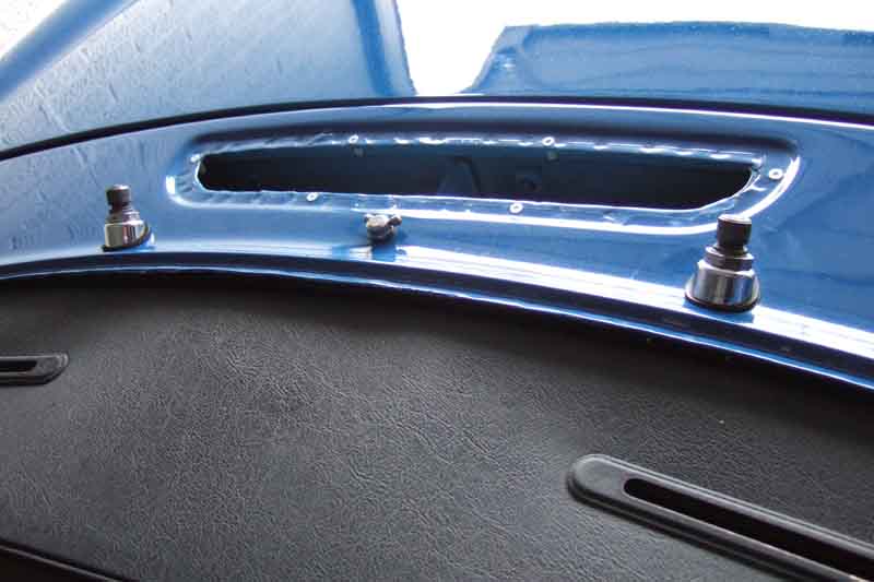
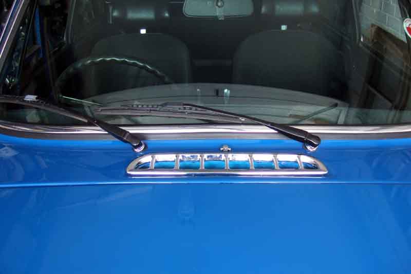
Fitted the wiper spindle covers and nuts - then realised I couldn't get the nut on the bottom of the central washer nozzle, so had to remove them again so I could pull the rack tube down out of the way. Then refitted the spindle covers, and pressed the plastic sockets into the panel for the air intake. I'd opened these out a little with a drill on removal, as I expected the paint to reduce them again, and I got it just about right. One being tight, and all the others firm. All the bright trim except this grille is in pretty good condition and will be reused, this grille has some pitting. I'll take a view on replacement later, the intention is to have Vee as a 'tidy driver', certainly not concourse or anywhere near. Subsequently realised I had forgotten to attach the washer tube, hope I don't have to remove the spindle covers yet again (I did!).
Then started on some electrics - joining up the main and rear harnesses, but the tracer colours are difficult to distinguish in some cases and I'll need things like the rear lights and reversing lights to be fitted before I can complete that. Finally installed the horns, plus clipped the harness to the front of the slam panel, and that was the end of another day. A lot of bending, twisting, contorting, and the full 'James Herriot' behind the dash, but not much to show, picture-wise, for all that effort. Next day is Sunday, so having a day off, before resuming next week.
Day 4 is a half-day, domestic duties in the morning. Fitted the rear lights and number-plate backing, the trim pieces over the cut-outs in the tailgate, finished off the harness interconnections in the engine-bay, fitted the passenger footwell side trim-piece that had been removed when the wing was replaced, and cleaned up and refitted the centre arm-rest.
Day 5 fitting the drop-glasses. Had to drill out the passenger-side rear lower channel bracket as the bolt had seized in the captive nut, the nut was no longer captive, and the bracket was loose on the door. Current brackets have two riv-nuts as they are universal - which needs a decision as to which one to use.
Day 6 was various bits including headlights, but really annoying to put one of the adjuster screws down in front of the car and it vanished. Also annoying to find I only have the bowl screws for one headlight, so fit both using just two screws, and have to order replacements. (Only to find it a few days later in the chassis rail channel where I'd put it for safe-keeping!)
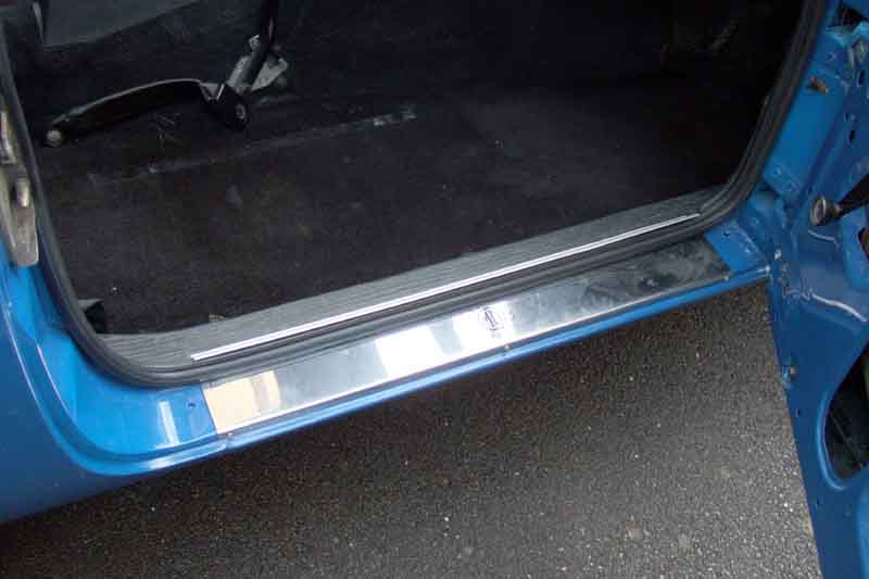
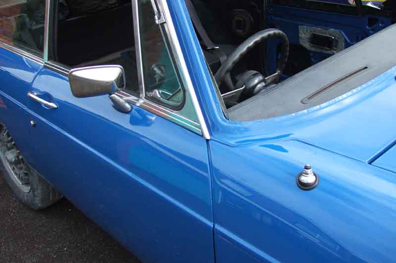
Day 7 fitting bits of trim including 'Spock's ears', threshold plates, door mirrors, and the aerial back into the front wing. Also give the wheels and tyres a wash so they don't look quite so bad. Probably some other hidden bits, which I can't remember as I'm writing this three days later and I've done loads so it's all a bit of a blur!
Day 8 is a big day - front and rear screens! Pal over for the day to help, five hours struggling with various aspects, more info here.


Day 9 various parts have arrived so I fit the tailgate lock and the rear number plate.
Also finish off the headlights, fit the front bumper, indicators, and the new front number plate. I'd used all-new bullet connectors behind the grille, and for all bullet connections burnished the bullets, and used Vaseline on all bullet and spade connections. Pleased to find the indicators tick at a decent rate even without the engine running, and the battery a little low as it has done so little running.
A couple of days off, and a morning waiting for some brighter weather. 'Day' 10 is an afternoon, and I get the rear bumper on, solder some proper bullets to the end of the HRW wires and connect that up ...
... fit the seats (to be recovered later), and the door trim including a moisture barrier behind the door cards made from DPC membrane (blue, as it happens!) and double-sided sticky tape.
Day 10. Bled the brakes all round using the Eezibleed, a little air out of the rears but none out of the fronts, or when I high-pressure bled the fronts. Pedal better I think, but still pumps up a little. The front bumper was closer to the offside wing than the nearside. Three spacer plates each side so took one out of the nearside with a view to putting it into the offside as the corner of the bumper between the headlight and the grille was very close to the body. But that would have left no threads protruding from the nuts that side, so I settled for three that side and two the other.
After lunch I decided to have another go at the front and rear screen trim, with a lot more success.
Wiper arms to be repainted.
Day 11: Had to order a special 6-way bullet connector as there are five earth wires by the right-hand headlight - one from the earthing point, one to the other side, one from the headlight, one from the indicator in the rubber bumper, and one from the cooling fans. I added local earths for the cooling fans, so strictly speaking the fan wire didn't need to be connected, but the better the earth the better everything will operate, and parallel earths are better than just one. That allowed me to fit the front grille ... and I almost forgot the chassis and commission number plates.
A break for the Bank Holiday, then over the next couple of days a bit of tinkering fitting the GB badges (nice sheen on the bumper) ...
... fitting the repainted the wiper arms and new intake ...
... and the new washer bottle.
Also fitted the rear cant rail with load-space light ... which didn't work. Testing showed that although 12v was leaving the fusebox it wasn't arriving at the wire that connects to the rear harness, which is only about 6" long! So ran a new one in. This is the second (the first being the solenoid operate wire) wiring problem discovered during recommissioning, plus an open-circuit in the alarm harness. Then checking tyre pressures, exhaust emissions and dwell (no adjustment needed), and a hot detergent wash to get rid of the remainder of the polishing compound in the channels and traces of Waxoyl round fitted parts, then a cold rinse, and leather. Looking pretty good now.
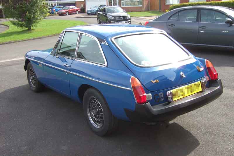
31st August 2017: She gets her MOT, 11 months and 2 days after starting this long and at times traumatic process!
1st September sees a Ł15k valuation from a local classic specialist, and she has her first decent run of about 30 miles to Warwick on local roads and back on the M40 and M42. Running really well, sounds and feels like she always did but without the horrible tapping from the engine. However the oil pressure is noticeably lower than before, even with this new front cover with the deeper gears which is supposed to improve hot pressures. Also a rattle on start-up, hot or cold which she never did before. With this donor block it could be clearances for the hydraulic tappets, which would cause both symptoms. I'll just have to see how it goes. Refitted the headlamp trim. Now to get some miles in and drain the running-in oil and substitute 20W/50.
Then another weekend away (South Downs Run) in Bee - 480 miles which would have been ideal for Vee, but I'm still building confidence. Next day I fit the side trim ...
... and the day after that get the badges and seat covers from Leacy.

Wing badges on the near-side only as per the original
Tailgate badges were originally slightly curved in both dimensions to suit the panel, but are made flat today. I put the V8 badge over a length of plastic waste pipe and lean on the ends and that puts a neat curve in the length, I can't see it needs one doing in the width which would be more difficult - needing a positive and a negative mould and quite a bit of pressure. The BGT badge is longer so should be easier, but it is also wider which makes it harder. Also it's not flat like the V8 badge, I don't want to end up buckling the edges, manage to put a bit of a curve in it and leave it at that.
Next day is dry and bright so sees another 60 miles on local roads out to Gaydon, and back on the motorway again, giving a range of low and high speeds, and acceleration.
Another day sees the backs of the rear wings and the sills (inner and outer cavities) treated with Dinitrol ML. This is much more liquid than Waxoyl even when cold, and stays liquid for a long time (it's definitely not thixotropic as some claim, that's Waxoyl) so penetrates the very narrow gaps between wings and sills easily. Good from that point of view, but for the accessible parts of panels I'd rather have it sticking where it hits, which is what Waxoyl does (unless you do it in very hot weather and it stays liquid). Then fitting those damned C-pillar trim panels! I replaced them a while ago, they were a pig then, and no easier this time. The holes aren't in the same places as the originals, and because the spring clips slide onto the edge of the hole, placing the 'point' of the clip off to one side of the hole, the trim panel holes have to be offset from the holes in the body. That means you have to work out where to fit the clip around the periphery of the hole, so the centre of the clip lines up the body panel hole. Then there is the screw at the top into the cant rail, and the two screws for the rear window latches. Add in the restricted space and awkward angles, and it is a recipe for much swearing. But eventually they went in. And for a bit of 'light' relief, I re-fitted the rear fog lamps. Installation was OK, apart from the back-breaking angle leaning into the hatch space removing and refitting the rear light clusters to get the wires through from behind the bumper ... to find they didn't work. The switch was lighting up, but no click from the relay. Couldn't see all the spades so had to remove it, to find no earth wire. That would be the earth wire I found in a bag with all the other fasteners from the engine bay and couldn't work out where it came from, and put in a Safe Place. No matter, a couple of minutes work to make up another, and they both work. Note to self: Return the tank and exhaust hanger to standard colours!
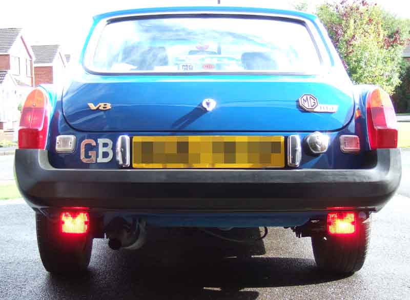
I won't bother putting the old front ones back on as one has been broken for years, and I haven't needed to use them for even longer. I may well fit the same DRLs as on Bee instead, as they will fit neatly under the rubber bumper.
Next day sees the plain water I had initially put in the cooling system (in case it had to be drained out again ...) removed and a 30% solution of anti-freeze put back. Halfords have changed the description, what used to be 'glycol' based is now 'silicate' based, but is it the same? It still makes reference to glycol in the safety info, so I hope so, but warns against mixing different types. So just in case I now have one top-up solution for the roadster (glycol), one for the V8 (silicate), and yet another (OAT) for the ZS! Checked the tightness of the hose clamps, ran it up through several cycles of the cooling fans and all seems OK.
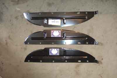 Sunday was a day of rest, then Monday pm I decide to paint the new splash panels prior to fitting - and find I have one for the near-side in one bubble-wrap pack and two for the offside in the other bubble-wrap pack!
That doesn't take along at all, so I decide to have a go at cleaning one of the rear wheels, and after that one of the fronts.
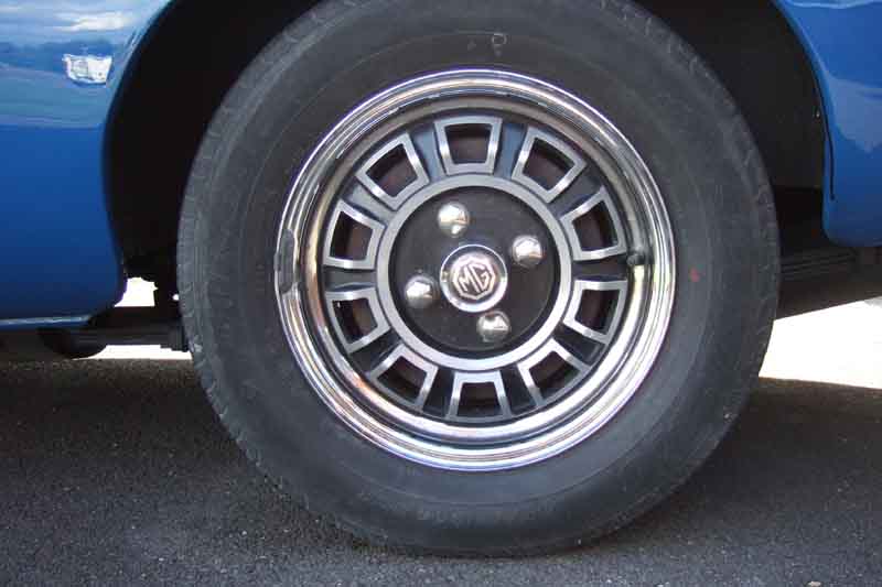
Tuesday is a 60-miler to the paint shop to show them the car in all it's glory, they and the chap from the unit next door taking pictures.
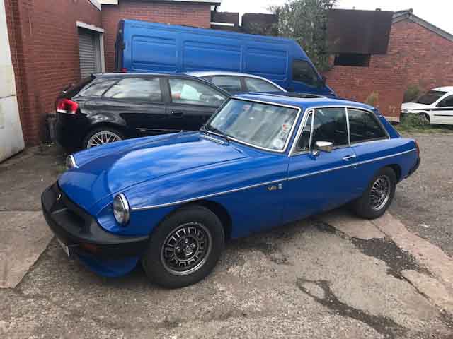
Wednesday the front wings behind the splash-panels treated with Dinitrol, the new splash panels and seals fitted, Finnegans underbody seal sprayed at the back of the wing by the headlight bowls (a mud trap and corrosion point), the new splash-panels and seals, and the backs of the wing and sill flanges.
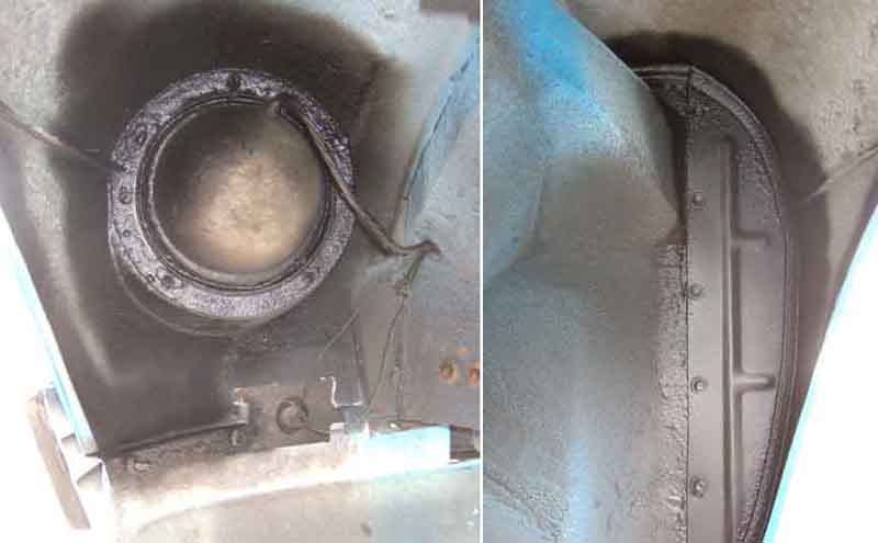
The old off-side panel was looking like Swiss cheese in the lower half.

Thursday sees the other two wheels cleaned - the first rear took me an hour, the first front and the second rear about 90 mins, and the second front about 2 hours as it turned out to be the worst! If I'd started with that one I might not have carried on. Note to self: Paint the brake drums!
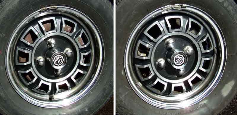
Friday sees another 60 miles, almost half-way to the oil-change now. Seat covers to be done, and I'm pondering whether to refit the front and rear mud-flaps.
Next week sees another 70 miles on a trip to collect a brake light switch (saving Ł6 P&P), and I decide to fit new mud flaps as one of the front ones was damaged years ago. Opted for plain white on black this time, instead of the red and white. Pal brought them up on a planned visit from a supplier local to him, saving more P&P, fitted them that afternoon, and subsequently modified them slightly and the clamping arrangement, which was less than ideal.
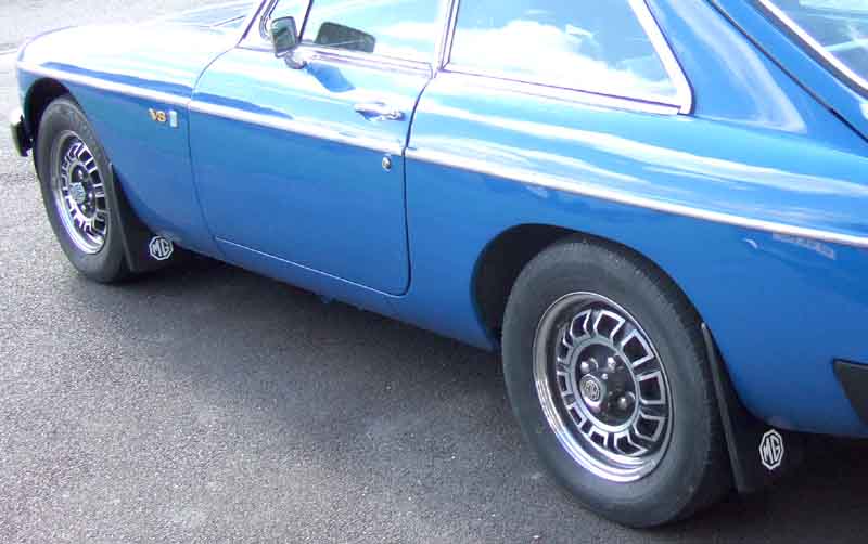
Friday sees another 100 miles, 90 to go!
The final week of September sees another 40 miles to get the Sunday paper, the brake drums painted ...
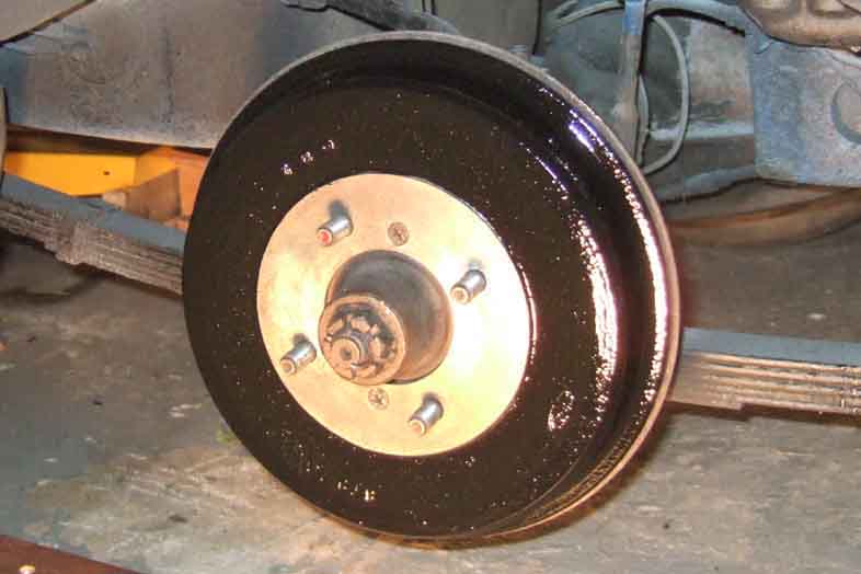
... the overspray removed from the tank and exhaust hangers ...
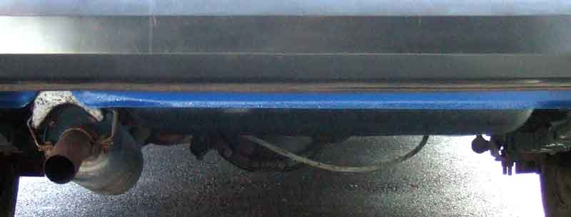
... and the final miles to 500.
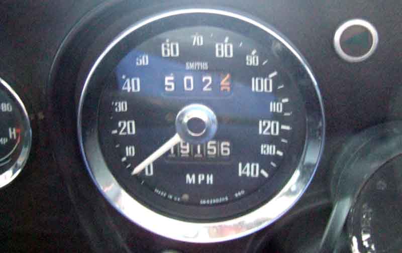
Next day change the oil (and the filter) to 20W/50. First start always takes a while to get oil pressure, the tappets are ticking but that would be 'normal' as they still have the remains of the running-in oil. Max oil pressure at a fast idle is as before i.e. about 38, no leaks, so onto the drive to check the hot idle pressures. Definitely better, once the fans start cutting in it's still 20, and over about twenty on and off cycles it only drops to 15 (at the end of the MOT it was barely registering). One interesting 'feature' of this rebuild is how consistent the cooling fan cycling has become, compared to before. However switched off, left a few minutes and restarted, I get the slight tappet rattle as before, so I'm just going to have to live with that. I still need to see what happens after a motorway run, then idling. That evening is pleasant so a run out to a local pub with a pal who has just completed a restoration on a TR4A.
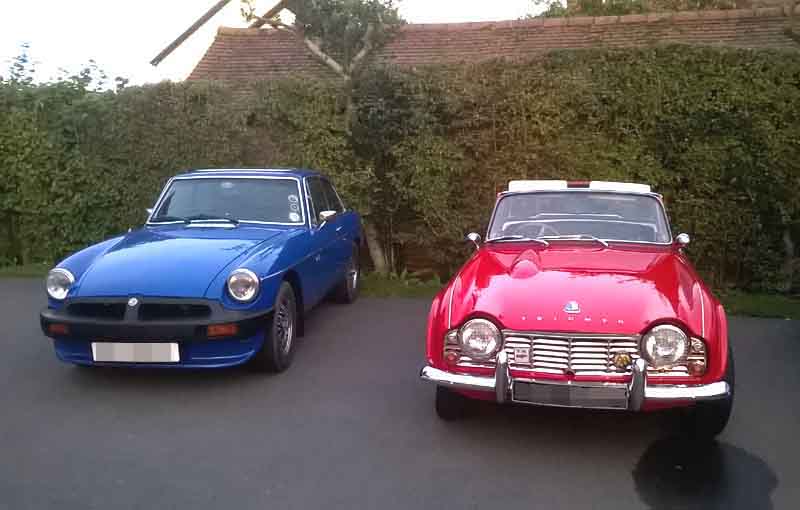
November, and I'd better do the seats before it starts getting too cold in the garage. Third time I've done recovering, foams and back-boards good enough to reuse, so only a couple of days of effort sees them out, done and back in again.
When I finished Bee's restoration in 1991 I wrote "Was it worth it? Very definitely! Would I do it again? Ditto!" and 26 years later I feel exactly the same way despite the initial traumas. Would I do it again? Yes, but probably not in 26 years!