


Contents
Index
So you think you want an MGB or V8?
Body
Brakes
Clutch
Cooling
Electrics
Engine
Fuel
Gearbox
Heater
Ignition
Propshaft
Rear axle
Steering and Suspension
Wheels and Tyres
Miscellaneous
Downloadable PDFs
The sectioned MGB at the British Motor Museum, Gaydon
Body and Fittings
|
From Lyndsay Porter's 'Guide to Purchase and DIY Restoration of the MGB',
republished as 'The MGB Restoration Manual', both by Haynes.
Fancy a reshell? Manufacturing an MGB bodyshell from British Motor Heritage
Front wing manufacture by British Motor Heritage
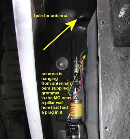
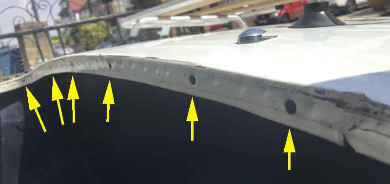
A frequent question in MGB circles is "How do I get to the aerial when it is mounted on a front wing?". After Martin Kennedy wrote and asked me that very question, having looked here for the answer and not found it, it prompted me to add this section.
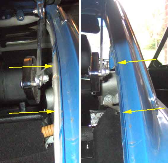
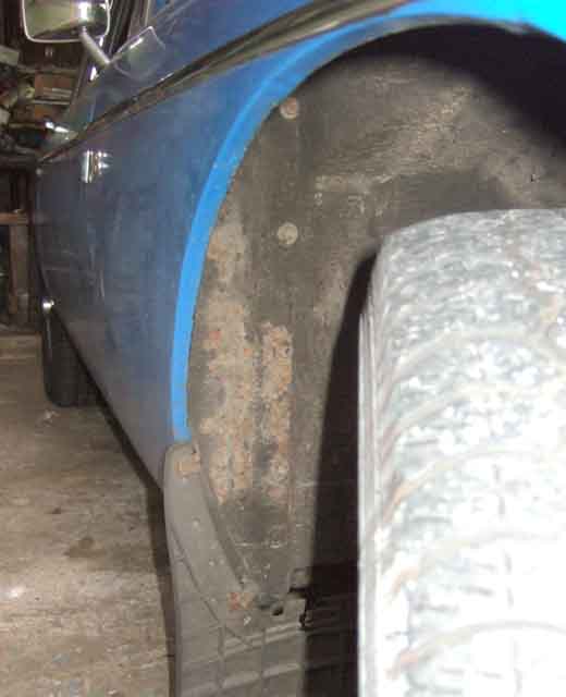 Behind each front wheel there is a 'splash' or closing panel which seals the gap between the front outside edge of the footwell and the front wing, having a rubber seal between it and the wing. There is also a small panel and seal for the gap between the top of the box-section visible from the engine compartment at the rear of the inner wing and the top of the wing.
The main splash panel is bolted to the footwell with seven bolts, the lowest one being up into the front of the floor pan and not visible in these pictures. Particularly the lower ones can corrode into the nuts welded to the panels, and shear off. In bad cases the corner of the footwell can crumble away.
With the splash panel removed you have access to the aerial, and also the hidden nuts for the door hinges. You can also examine the front section of the sills and the lower edges of the front wings for corrosion, and dribble oil down the very narrow gap between the two as described in 1/4 panel replacement above.
Added October 2008:
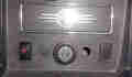
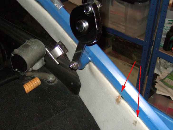
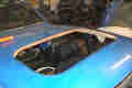
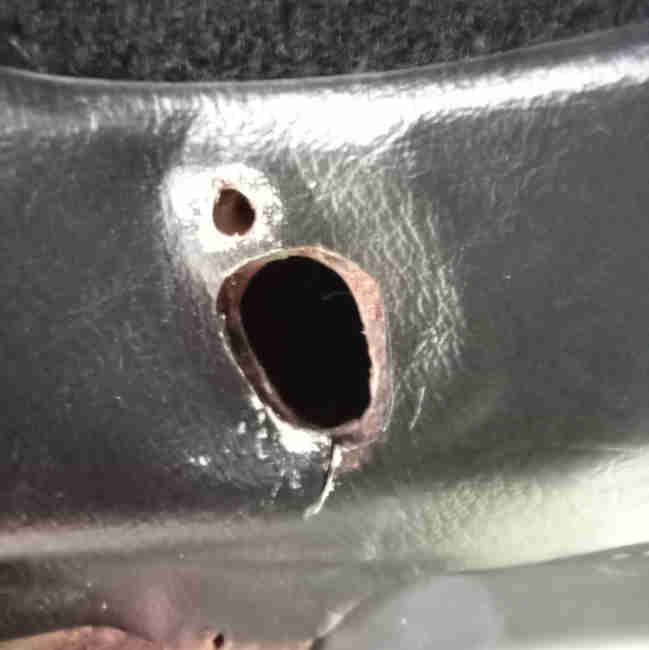
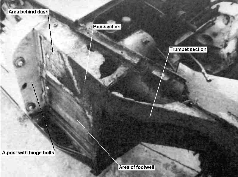 One thing to consider when adding an aerial to a front wing is the box-section that is immediately below it and behind the inner wing - see the accompanying thumbnail. There should be one or two large holes in the inner wing to enable you to see inside this box section, and the main harness and accelerator cable go to the cabin via it. If you drill the hole in the outer wing too close to the seam between the wing and the panel at the base of the screen you will also have to drill a hole in this box-section. Even then if you have a manually fully retractable aerial it may foul the bottom of the box-section, and a motorised aerial probably won't be able to be installed at all. The box section goes all the way forward to the splash-panel, and then there is a tapered 'trumpet' section in front of that, so you would have to go all the way forward to just about the front axle before you get a clear space under the wing if you are too close to the inner edge.
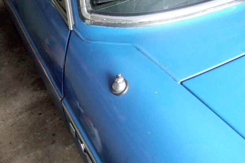 However by positioning the aerial close enough to the outer edge of the wing there is plenty of room between the side of the box-section and the side of the outer wing for any likely aerial. This means mounting the aerial on a curved and angled surface rather than a flat and horizontal surface, but all the aerials I have seen have a fitting that can cope with this kind of location.
July 2022: Mark Denny has sent me this PDF from Radiomobile showing dimensions for positioning a front wing aerial on both roadster and GT.
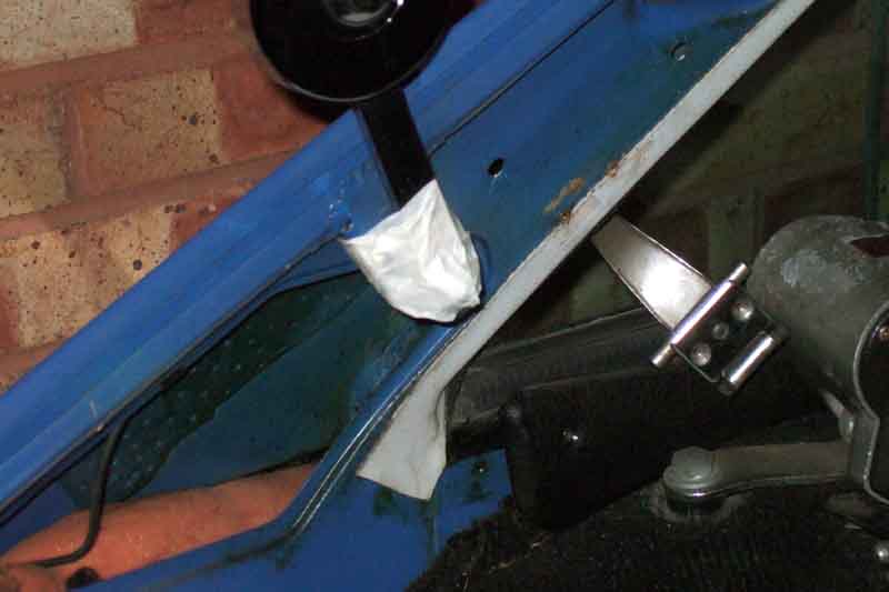
 These pictures from Paul Tegler show a motorised aerial in the process of being installed behind the splash panel.
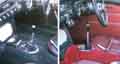
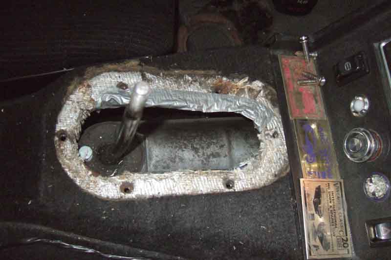
Arm-rest Cubby & Centre Console Added July 2009
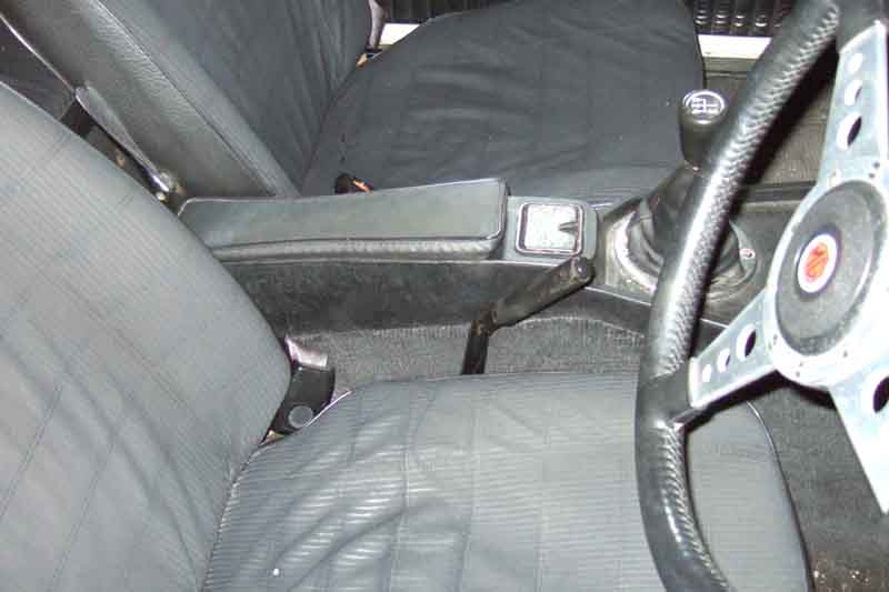 1972 models for all markets got a modified centre console incorporating a hinged arm-rest with storage space underneath. There is a plastic peg attached to the lid, and a spring clip on the base, but the way they have been installed results in frequent breakages of the plastic peg unless you are very careful to align the peg in the slot in the clip before pressing down. Because there is just a simple hinge at the back of the lid it allows a lot of sideways movement of the front of the lid, but the peg and clip were fitted such that this sideways movement puts the greatest stress on the plastic peg in its weakest direction. If peg and clip had been turned through 90 degrees the weakest direction of the peg would then be to fore and aft movement of the lid, of which there is very little if any.
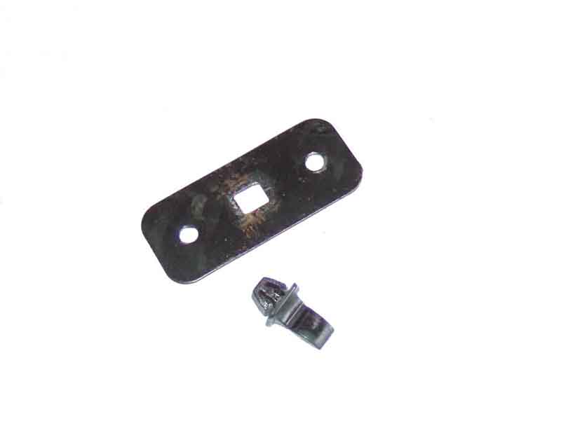 Fortunately it is quite easy to turn the peg and clip through said 90 degrees. The peg is easiest as it has a square fitting, just squeeze the lugs on the back with a pair of pliers and push it out, and it will snap back in after turning (it's actually a fraction off-square but will go in the new way with just a bit of a push). The clip requires a bit more work. It's a little bit rectangular, which means the sides of the slot have to be filed out slightly. The overall width of the clip is greater than the length of the hole in the console, so will cover the sides of the hole if you are careful in your filing. Only file the minimum width needed for the clip, and in the middle of the sides of the hole, which will stop the clip sliding fore and aft and revealing the edges of the old hole (as well as nullifying the point of the exercise by putting the peg out of alignment with the clip again).
 Also only file enough to just be able to get the clip pressed into the new hole, if you file too much the clip will be pulled out of the console on the end of the peg.
 However even if you did that (as I did on the roadster many years ago) all is not lost. There is a depression in the console that looks as if it were designed to take a mounting plate for the clip, complete with two blocked-off holes for fixing screws. It's a simple matter to cut a plate to fit this depression, drill through the plastic console and use countersunk screws to attach it, and it is much easier to get a tight-fitting hole for the clip in the plate than it is in the plastic.
June 2021: An enquiry about this on the MG Enthusiasts forum and Stephen Strange comes up with "The simplest solution is to glue on two strips of Velcro, one on the underside of the armrest, and the other over the hole in the console." A different kind of 'lateral' thinking!
May 2022 Another enquiry about repeated breakage of the peg on the MGOC forum, despite the poster already having turned peg and socket through 90 degrees. He must be pretty ham-fisted with it, or the hinge is very sloppy in the fore and aft direction as well as from side to side, but there we are. Someone suggested Velcro but another opined it would be difficult to lift the whole strip away in one go as usually they are peeled apart. That's true, but then it depends on how long the strip is. Another suggested a rare earth magnet and a metal plate (which is already in the lid) but going by the ones I have that would be even more difficult to pull apart, unless you recessed the magnet well down in the base to give a significant air-gap. I have a couple of stacks of 15mm discs and the only way I can pull them apart is to 'break' them like you would a stick. One disc would be less of course, but it would need some pretty strong glue, or more likely it would need to be under a metal plate (with a hole) screwed to the base. In the end the poster made a peg out of a screw, filed down to the correct shape and size, and held to the lid plate with a nut.
Herb Adler describes making and fitting an arm-rest cubby to a pre-72 model.
Centre Console: July 2022
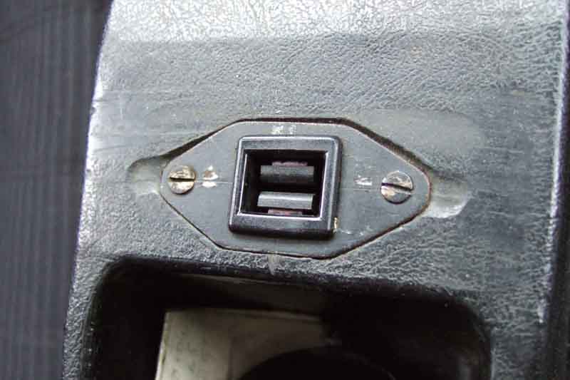
 Originally the centre switch and radio console for roadsters only had a cigar lighter in the middle, with a rectangular and a circular blank either side, GT's had the heated rear window switch and warning light to the right of the cigar lighter. V8s and RHD RBs (North America had them with the Mk2) gained a hazard warning switch, which didn't have an additional warning light (unlike North America) so one circular blank remained. Bee being a 1973 roadster came to me with four blanks (until I added hazards) but one of the circular ones was missing (which no one seemed to list) and for many years I covered it up with a small greetings card. But that got tatty and kept coming unstuck, so did some Googling. The existing blank measures about 3/4", and I spotted ACH9373 for classic Minis which is classed as a switch blank. Googling that Rimmers came up with that part for the ignition switch blank on MGBs with toggle switches when they got combined steering locks and ignition switches, and several places including MGOC came up with the same number for banjo brake drums! The MGOC item was an eBay listing for two for �2.50, which although it had a postage charge it was about half what supplier websites (including MGOC) were quoting, so that gets my order. They are chrome whereas the existing one is black, but that isn't a problem. When they arrive they are a loose fit in the hole, but as they (and the one I have) consist of a number of springy legs round the back that go through the hole it's a moments work to bend four of them out a little, and Hey-Presto, a good fit. They also have a very slightly domed face whereas the original is flat, but I don't think that will be an issue - if I don't like it I'll fit both and keep the original as a spare!
Rubber
Lashing brackets
Chrome Bumpers: Just a warning that there have been some poor copies of chrome bumpers from some sources - incorrect in shape as well as poor in quality. Whilst the latter is not always easy to confirm before purchase, you can at least check that the basic shape is correct. One problem has been in the ends of the rear bumpers. Originals are tapered in towards the wing leaving a very small gap as further back, whereas copies have them chopped off short leaving an open hole facing forwards. That's the biggest and most obvious, there are other more subtle differences such as the part facing forwards is shorter, perhaps in an effort to correct the first problem. I'm not aware that this also occurs with front bumpers, even though the ends are very similar. Bob Muenchausen has some useful comparative photos here.
Mounted on 'springs' bolted to the chassis rails at the front, at the rear the springs were bolted to 'irons' that were bolted to the chassis rails and protruded through the rear valance.
Over-riders:
 Originally front over-riders were optional for the UK until 1966, standard elsewhere, although Clausager says it is rare to find a UK car without them. Many changes detailed in Clausager, but basically they were plain chrome until 1970 or 1971 and were the same each side, then had rubber facings and became handed. The all-chrome (AHH6916 front, AHH6489/90 rear) have a welded bracket with nut inside for a standard bolt that comes through from the other side of the mounting 'spring'. Originally the rubber-faced type (BHH377 front, BHH378/9 rear) used a long special bolt with the head under the rubber facing going through the mounting spring with nut screwed on from the other side of that. Some suppliers have these with the long bolt and facing strip already fitted, some a kit of parts including the bolt, some supply that type without the special bolt so you have to order it separately, and some have them with the earlier welded bracket which needs a shorter standard bolt.
Originally most markets had the number-plate lights on the rear over-riders until almost the end of UK chrome-bumper production when they were mounted on the bumper itself directly below the plate. North American spec for 1970 only had half-bumpers with the number-plate lights tucked inside the ends, and for 1974 immediately before rubber bumpers they had large all-rubber 'Sabrina' over-riders. These were mounted further outboard almost directly inline with the bumper irons, both design and position in order to pass early impact tests. Consequently the bumper and its mounting were significantly different, with only one thicker spring going the full width of the car. The over-rider with its underlying metal structure bolted through the bumper to the spring alongside the mounting point of the spring to the bumper iron, and there were three (instead of four) more mounting points for the bumper to the spring - two at the ends as before and one in the middle, using chrome-headed bolts. For this reason this bumper is significantly different to any other full-width bumper and you have to be careful when buying replacements, as one UK chap with a UK car found when buying from a UK vendor.
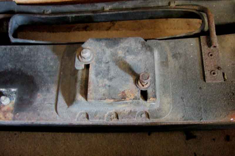
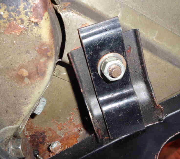
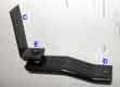
Lashing brackets: October 2018:
 Both chrome and rubber bumper cars were fitted with 'lashing brackets' of various types at various times, used for tying down new cars when exported by sea, sometimes called 'towing eyes'. Early cars from July 62 to November did have a towing eye attached to the front crossmember, deleted at the same time the front lashing brackets were provided.
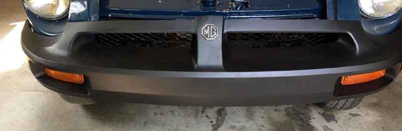
Left to their own devices these get dull, rough and greyish with exposure to road dirt and sunlight especially when kept outside facing south as Vee was for several years.
Having tried a couple of products I used to recommend Turtle Black Chrome but it is no longer available. It is quick and easy to apply, brings tired bumpers back to black and shiny, and they stay that way for ages. A subsequent application several months after I got them to a good shine made hardly any difference, they were still so good. It has the same effect on various items of black trim of different materials on my 89 Celica although I only use it on the bumpers on the V8. It is a black almost creamy liquid, and a word of warning, if you get it on paintwork you can only get it off again with car polish, so I slip sheets of paper behind the edges of the bumpers while I am applying it. Turtle Wax Trim Restorer seems to be the current product, or maybe Black in a Flash, but I haven't tried either yet.
I had previously tried ArmorAll and sure enough with enough applications left to dry in the sun and then finally polished up you could get them back to black and shiny, but the effects faded very quickly, in fact they seemed to end up rougher and greyer than originally, even when not exposed to sunlight for long periods. Some recommend its use on interior vinyl but others say it dries it out and can cause it to crack in the sun. Having seen the effect on the bumpers I can believe it. About the only thing it is good for is tyres for a show finish, being better than that awful high-gloss tyre paint beloved of second-hand car showrooms. But if you are going to drive the car don't bother, after a few dozen miles the effect has worn off.
Another recommendation I have seen is black boot polish, and whilst I can believe it works I can also believe that it will rub off black on light-coloured clothes even after being polished up. I say this after having had to clean a light-coloured carpet where someone with highly polished shoes had been shuffling their feet.
August 2020: Howard Aris writes:
November 2021: A perennial question, these suggestions on the MGOC forum:
- Autoglym trim and bumper gel. Looks like snot but it's really good stuff. Wipe on, wipe off. The more coats you apply the deeper the shine. After about 5 coats it starts to develop an almost mirror like finish.
- I use Car plan rubber black gel and rub it off after a while then spray Simoniz Back to Black in a aerosol can and just leave it.
- Current winner by a country mile IMO ......Vaseline !
- Black boot polish - Black Beauty was the brand
- I use Meguiars Tyre gel... great on tyre walls so I thought I'd try it on the RBs and it leaves a lovely shine if that's what you're after.
- The best thing to use on those black rubber bumpers? A spanner to take them off!
Mounting:
 The front bumpers have four studs screwed into the armature - two each side, with washers, lock-washers and nuts fitted behind the chassis brackets. There are usually several slotted spacer plates fitted between the armature and the brackets to position the bumper as close as possible to the wings without touching, mine have three each side. Unlike the rear bumper the outer corners are unsupported.
The rear bumper has five studs - two each side one above the other and one centrally in the upper position, the upper three going through into the spare wheel space and the lower two below the floor. In this case the outer corners are supported by one bracket each side. However it is not necessary to unbolt these from the body to remove the bumper, as the bumper has slots which slide off the brackets.
Strip/Refit: February 24 A pal chose to do this as an NOS cover came his way, and it may also be necessary if either your cover is ratty or armature is corroded and you want to mix and match with another. Info from said pal regarding fitting is:
Carpet and mats
Tunnel
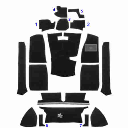
 Probably the most important decision to be made, even more than quality, is which tunnel shape is needed as the two available are very different. Mk1 cars have a humped tunnel, and Mk2 have a flat (albeit wider) tunnel.
 The next is whether to get a moulded, or the cheaper flat. Without a doubt the moulded fits better, and flat will almost certainly be of a lower quality, but to be fair with the Mk2 tunnel and the centre arm-rest/cubby the wrinkling that results from a flat carpet is between the tunnel and the seat and only visible if you look for it. I did buy cheap as part of a full repaint and retrim, but that was 32 years and 65k ago wet and dry and they are still as good as new. But then I've always used rubber floor mats in all my cars, which do save the front floor sections from a lot of wear from heels.
There is also a decision on sections for the rear arches. These have a double-curvature and are a real pain to get a neat fit from a flat section even when glued, I had to cut darts. Some kits with the moulded tunnel have these moulded as well as in this GT kit, and some don't.
 If you have a 72 and later car with the centre arm-rest and cubby, cut the carpet around the small access panel as well as round the gear lever hole, which means you don't have to pull the tunnel carpet back to access the gearbox switches. Keep a piece to drop on top of the panel when refitting everything. Click the links for more on the reverse light switch, and the overdrive switch.
'Starter Cover' Mat
 Aka RHD 'clutch foot rest cover'. A moulded rubber mat that goes over the starter motor bulge in the right-hand footwell, AHH6443 for Mk1 and AHC98 for Mk2.
Boot/Hatch
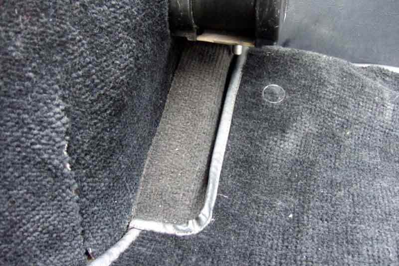
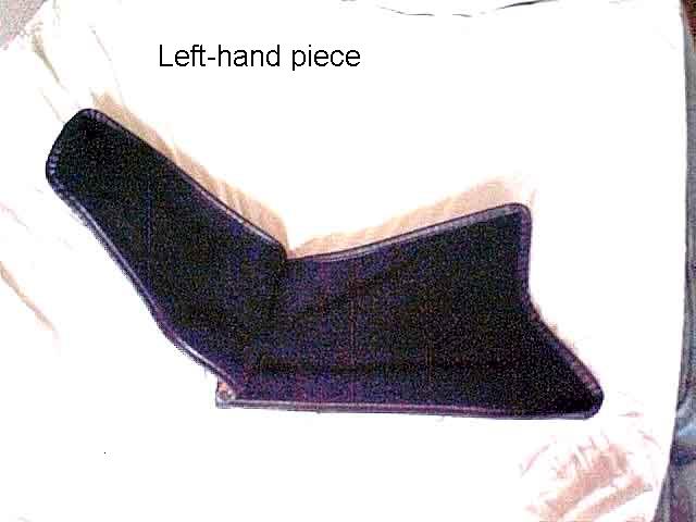 Two strange pieces of carpet (amongst many) fit immediately in front of each rear light cluster. One flat squarish piece glues to the inside of the rear wing in the space that is bounded by the back of the rear wheel arch, the boot floor,
the rear light cluster, and under the boot lid rim (roadster) or C-post trim (GT). The other is two pieces stitched together such that the natural inclination of the 'hinge' is for the pile-sides to fold together. The wider half lies on the side piece of the boot floor and the narrower half covers the back of the rear light cluster. Both pieces are handed so try them both sides for the best fit.
Two strange pieces of carpet (amongst many) fit immediately in front of each rear light cluster. One flat squarish piece glues to the inside of the rear wing in the space that is bounded by the back of the rear wheel arch, the boot floor,
the rear light cluster, and under the boot lid rim (roadster) or C-post trim (GT). The other is two pieces stitched together such that the natural inclination of the 'hinge' is for the pile-sides to fold together. The wider half lies on the side piece of the boot floor and the narrower half covers the back of the rear light cluster. Both pieces are handed so try them both sides for the best fit.
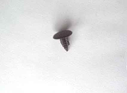 The narrow part that covers the back of the light cluster is held in position by a plastic trim fastener pushed through the carpet into a bracket, but neither the bracket nor the fastener are shown in the official parts lists I have. The roadster didn't have these brackets so it was always a bit of a puzzle how the 'hinged' pieces were supposed to fit. It wasn't until I got the V8 which happened to have just one of these brackets and fasteners that I realised, and I was able to make three more brackets using the existing one as a pattern. I was able to get suitable fasteners at Halfords from their range of generic trim fasteners at the time. These are black plastic, have a 15mm diameter head, 17mm overall length, 15mm shank length. The shank has serrations and a maximum diameter of about 7mm.
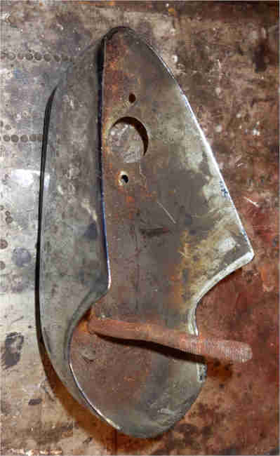
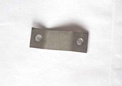 I made the brackets out of some bits of body panels I had lying around (Hunts Eighth Law: "If you haven't found a use for something yet, you haven't kept it long enough"). All measurements are approximate but these are taken from the one original bracket I have. It isn't critical, it isn't visible, and I doubt even a concourse judge would be looking at them.
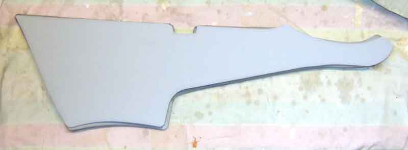
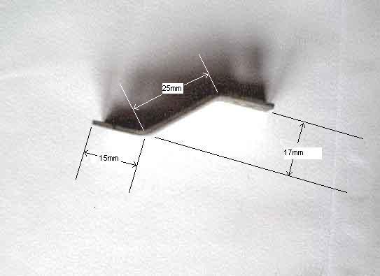 For each bracket cut a flat strip 19mm wide and 55mm long. Mark a line across the width 15mm from each end, this is where a bend of approximately 40 degrees is made. Mark and centre-punch the centre of each 19mm x 15mm area for the hole to accept the plastic fastener. Get the fasteners and drill a hole of suitable size for them but in my original they are 6.5mm diameter. Finally make the bends so you end up with something like in the picture at the left.
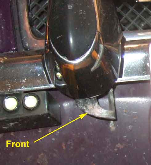
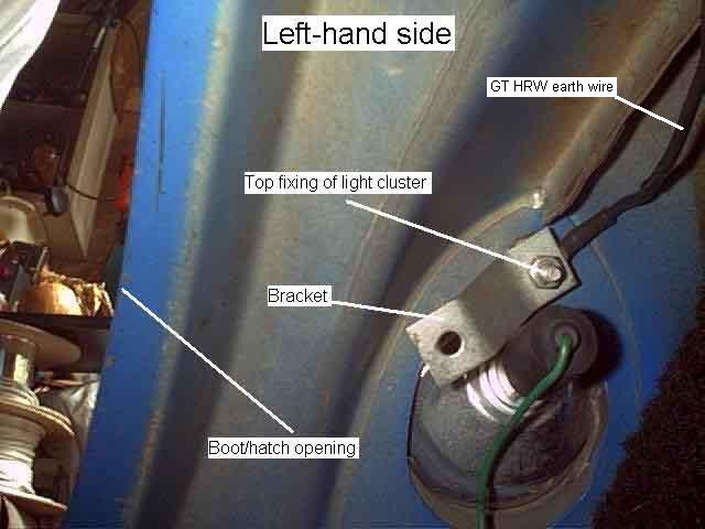 The bracket is secured on the top stud for the rear light cluster and held by an additional spring washer and nut. It is angled down and towards the boot/hatch opening,
as shown in the picture on the left. The plastic fastener pushes through the carpet and into the free hole in the bracket.
The bracket is secured on the top stud for the rear light cluster and held by an additional spring washer and nut. It is angled down and towards the boot/hatch opening,
as shown in the picture on the left. The plastic fastener pushes through the carpet and into the free hole in the bracket.
Battery 'shelf'
 The wheel arch and battery shelf pieces leave the chassis rails exposed, so I cut and glued some additional pieces for a neater appearance.
Mats:
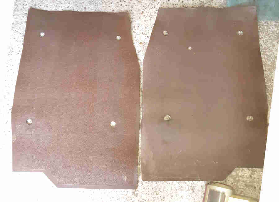 From inception until the Jubilee of April 1975 had 'PVC coated' (Clausager) rubber floor and sill mats, other models kept them until the start of the 1977 model year. They always matched the main interior trim 'so could be black, red or blue' although the heel mats in front of the seat were always black, regardless of trim colour. Vee still has original black ones under the POs carpet under the seats and on the sills but the front ones were missing when she came to me. Mark Denny sent me these pictures of a pair of rears which seem to be in Autumn Leaf, which was a new trim colour for 1971.
Cable and Pipe Routing July 2019
 For Mk1 cars all markets used the same main harness, designed to reach right across the car for LHD, turned back on itself behind the dash for RHD. For Mk2 and later cars even though there were separate North American harnesses this was more to do with additional circuitry for that market rather than differences between LHD and RHD, other LHD markets and the UK seem to have continued to use the same 'LHD' harness turned back for RHD cars. It wasn't until the 77 model year that all LHD roadsters conformed to the North American spec, at which point there was a RHD-only harness, a LHD for Canada, and another LHD for America and the rest of the LHD world. The V8 also had an RHD harness as it was never marketed in LHD form, even though seven were built for Federal testing in the USA, which probably had the North American dash, harness and everything else that market required.
 Tank to pump, and
convenient pictures from Clausager showing how all four 'services' - brake pipe, rear harness, battery cable and fuel pipe (from outside towards the middle) are routed through four small rubber combs (AHH6286) secured with metal straps (AHC60) to studs on the floor pan, plus a larger comb (AHH6284) and strap (AHH6285) where they all pass through a channel in the fixed crossmember. However at some point - probably as the rear harness gained the extra wires for reversing lights (1967), split parking lights (1970), boot/load space light (1971), and GT HRW (1971 or 72) it maybe became too fat to follow that route, and went through a separate hole in the fixed crossmember and P-clips beside the other combs. Another change was on Mk2 cars with the wider tunnel where the inboard stud for the front small comb was lost - a slotted tab was welded to the side of the tunnel and the end of the retainer strap pushed through that, being secured by one stud on the outboard side.
Tank to pump, and
convenient pictures from Clausager showing how all four 'services' - brake pipe, rear harness, battery cable and fuel pipe (from outside towards the middle) are routed through four small rubber combs (AHH6286) secured with metal straps (AHC60) to studs on the floor pan, plus a larger comb (AHH6284) and strap (AHH6285) where they all pass through a channel in the fixed crossmember. However at some point - probably as the rear harness gained the extra wires for reversing lights (1967), split parking lights (1970), boot/load space light (1971), and GT HRW (1971 or 72) it maybe became too fat to follow that route, and went through a separate hole in the fixed crossmember and P-clips beside the other combs. Another change was on Mk2 cars with the wider tunnel where the inboard stud for the front small comb was lost - a slotted tab was welded to the side of the tunnel and the end of the retainer strap pushed through that, being secured by one stud on the outboard side.
December 2020:
 Boot/loadspace routing: CB cars have the tail for the fuel tank sender leaving the rear harness in the boot and exiting through a hole by the off-side light cluster to go forwards to the sender. RB cars have it leaving the harness under the floor above the axle and travelling back to the sender.
January 2020:
 Bulkhead holes and grommets.
October 2019:
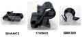 MGSte writes that the edge clips that attach the harness to the slam-panel are BHA4473, brake line clips are 17H9603 (3/16), and fuel line clips are BMK385 (1/4). Only the last is listed in my Parts Catalogues, but all are listed by the usual suspects.
Cockpit Rail August 2018 - initiated by Dave Farrar
 The hood frame and/or tonneau sockets and the trim panel aft of the doors will need to be removed, to remove and refit the cockpit rail. The trim is glued to the moulding. Start at the middle and glue along the curved face, piping uppermost and flush with the back face, and work round to the ends, don't trim at this stage. A warm day or gentle heat will be needed to stretch the vinyl round the back of the moulding in the corners.
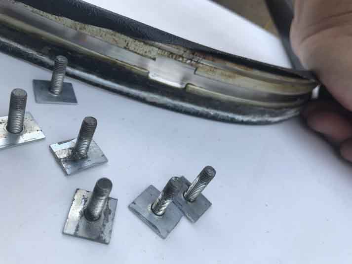 Slot the studs into the channel through the cut-outs, and fit the end-plates into the channel such that the exposed part is flush with the back of the moulding. Only then trim the vinyl to the ends of the end-plates as this goes under the trim panel aft of the doors.
 There are nine holes around the edge of the cockpit, through which go the threaded part of the studs, then plain washer, spring washer and nut fitted. This is a bit of a fiddle as they are accessed from below inside the cabin, and you need dextrous fingers to get the washers on and the nuts started. A 2BA spanner is best for tightening the nuts in the limited space available, don't over-tighten and strip the threads.
Dashtop and Crash-roll
Mounting
Gauges
Glovebox
Heating and Ventilation
Horns
Ignition Switch
Lighting
Radio
Screen Washers
Wipers
Originally metal painted in black wrinkle-finish, RHD changed to plastic for the 1977 year on. North American Mk2 were completely different but became similar from the start of 1973 with central air-vents and regaining a glovebox albeit in plastic, changing to a different plastic type for the 77 year on.
Dashtop and Crash-Roll A vinyl sheet is glued to the metal dashtop panel on roadsters, with the front edge tucked under the screen frame seal, and the rear edge behind the crash-roll on the dash. GTs have the vinyl glued to a 'hardboard' panel, with the front edge tucked back under the panel instead of the screen seal, but the rear edge is behind the crash-roll as on roadsters. Heater vents sit on top of the vinyl with studs through to the underside of the metal panel. Various suppliers show vinyl for recovering both the dash top and the crash-roll as part number AHH7597.
 The ply backing for the crash-roll can get pretty flimsy after many years and the studs pull out. My original was breaking up, and anyway it looked a fiddle to recover as a staple-gun would be needed man enough to staple through the vinyl and the piping into the ply, because of that I opted to replace mine complete. Originally BHH947 now AKE5155 from several suppliers and seems to come with the vinyl for the dash-top i.e. in place of AHH7597, the quality of vinyl wasn't so good being less textured than the original. Secured to a flange on the dashtop with eight nuts FNZ103, spring washers LWZ203 and plain washers PWZ103. One 'Push-on fix plug' is listed under the crash-roll parts in the Leyland Catalogue but this seems to relate to the blanking plug and spire clip fitted in place of the dash-mounted overdrive switch when OD is not provided.
Mounting July 2023
 Brendan Hussey asked me about this as fitting his dashboard as per photos on an MGOC Forum thread he just could not get it to fit neatly. The dash has brackets that fit over studs under the scuttle, and there is an additional plate AHH6293 (NLA but may be available from breakers if lost) for each one. The dashboard brackets are purely used for location, it's the plates that give the required support. The MGOC forum post described these plates as 'spacers' (other fora stated that they went somewhere else altogether) and showed them between the dashboard brackets and underside of the scuttle i.e. going on the studs first, but that is incorrect. They go on afterwards, under the dash brackets, and clamp those to the underside of the scuttle.
| Car | Overall Length | Overall Width | Overall Height |
| CB Roadster | 12' 9.2" | 4' 11.9" | 4' 1.4" |
| CB V8 | 12' 10.7" | 5' 0" | 4' 2" |
| RB GT | 13' 2.25" | 5' 1.75" | 4' 3" |
I'd not really thought about the width differences until I got copies of the 1977 and 78 Leyland Workshop and Repair Operation manuals where the width is given as 4 ft 11 and 15/16 inches or 1523mm, i.e. 4' 11.9" which is the same as the CB roadster in the earlier manuals. I'd put the difference between CB and RB down to the bumpers, but in fact the widest part of the car is between the doors. Then I realised that my door mirrors add another inch per side, and wing mirrors would possibly add even more. I measured my V8, including door mirrors, at 5ft 2 and 3/4in, or just over 2 3/4" more than the 77 and 78 manuals, and an inch more than the earlier Workshop Manual.
Drinks Bottle Holder Added September 2009
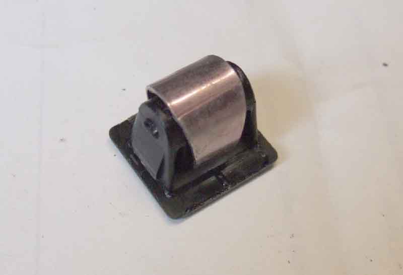
 The Navigator likes to keep a small bottle of water with her, but it keeps rolling under her seat so she has been nagging me to install a holder of some kind. Hadn't given it a lot of thought, but while I was rooting through my box of old MG bits for something else I came across a broken windscreen washer bottle holder that I had replaced when I first had Bee 20 years ago. The frame between the two mounting holes had broken away, but I realised it would make an ideal 'holster' for the small water bottles she uses.
My first thought was to mount it above the sill in the footwell somehow, but that would probably have meant screwing through the trim panel which I didn't want to do. Then I investigated hanging it from the square-section bracing tube behind the bottom edge of the dash. Possible, but it would have to hang several inches down and not swing about. Looked along the tube towards the centre console to see the two brackets for the LHD steering column, which were a definite possibility, but again the holster would need to be lower and not swing about. Then my eye fell on the lower screw in the side of the centre console, and Bingo, the ideal location.
Repaired the frame by welding a strip between the two broken holes, and re-drilling the top one, did a test fit and it looked fine. However the water bottles are quite a bit smaller diameter than the washer bottle and if at an angle in the holster would fall through the frame. Started pondering welding more strips around the bottom, but then I seemed to remember I had replaced the water bottle as well when I replaced the frame because it was holed and leaking. Another root through the box of bits and Lo and Behold! Cut the top off the washer bottle to just below the top of the frame, perfect. Then it was just a matter of stripping and painting the frame, and installing.
October 2017:
 I say 'perfect' - and I'd done the same to Vee - but being against the tunnel the bottle did get a bit warm in hot weather. When Vee had been restored the passengers side trim panel had been removed to replace the front wing, and when I came to refit it I realised that - unlike Bee - there is a trim-screw half-way up the edge by the door. That makes a convenient mounting point, although it rather forces the height and angle the holder has to be positioned at. That proved just fine, so I moved Bee's across as well.
Front Valance January 2022
LE models had an additional rubber 'scoop' spoiler on top of the standard metal valance below the bumpers and this may suffer from the same problem. The ST spoiler adds significantly to cooling on RB models with the under-slung oil cooler, and particularly the deeper radiator on V8s and 77 and later 4-cylinder cars, as described here. The LE spoiler may offer the same benefits.
Glovebox June 2019
 Fittings: The fibre-board 'box' is available (AHH6338 for RHD and AHH6339 for LHD) from the usual suspects. The brackets that support the back of the box (HZA545 and HZA543) are NLA but can be fabricated quite easily. Two parts originally, but I'd say not much more than a simple 'L' bracket performing both functions is needed.
What to do when you lose the key: The Heritage Certificates for Bee and Vee give the key numbers - one for the ignition and one for the doors, boot/tailgate and glovebox. It's quite likely that the external locks have been changed at some point, much less so the glovebox, and the likes of Moss and Brown & Gammons plus other BL model parts houses sell replacement FS keys. Failing that you could drill out the lock and replace that (�15), or maybe even remove or destroy (and replace - �25) the fibre-board glovebox itself to get at the back of the lock. A 9/16" socket fits the screw that hold the tongue onto the barrel on Bee and Vee, and with that removed the lid should fall open.
 But I hate destroying things if there is another way, which is to remove the five screws holding the lid to the dash, then slide it to the left as far as it will go, tilt the left side down and the lock tongue should come out of the slot in the dash panel. The images also show how the fibre-board 'box' is attached to the dash panel.
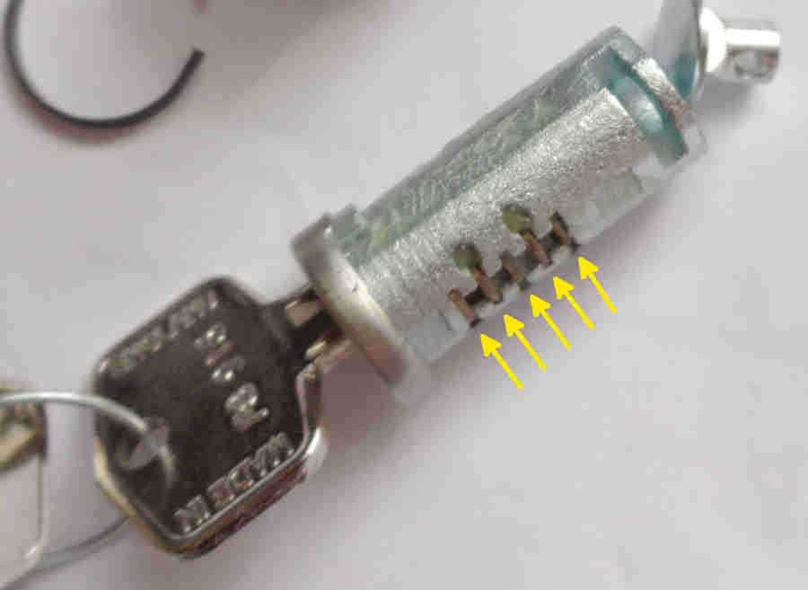 And failing that, the lock is a very simple three-tumbler affair that should be quite easy to pick - I managed it in a couple of minutes.
And finally, if you only have one key now, get another and hide it in the car where you can get at it without any keys!
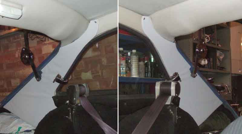
GT C-post Liners November 2014
 When I bought Vee 20 years ago come January bodily she was in very good condition, and apart from one thing the interior was also good - patinated but very original. The exception was the C-post liners, where the nuts on the back of the tail-gate spring stays had been allowed to gouge the vinyl of the C-post liners. Really annoying, as all it took was a little force to bend the pivots in towards each other a little bit so they cleared the liners. That left what to do about the liners. Never in a rush to do things (it took me 18 years to replace the plastic covers on the tail-gate struts ...) I decided now was the time, so as I had built up a list of things I wanted to do on both cars over winter I went on a shopping trip to Motaclan/Leacy's.
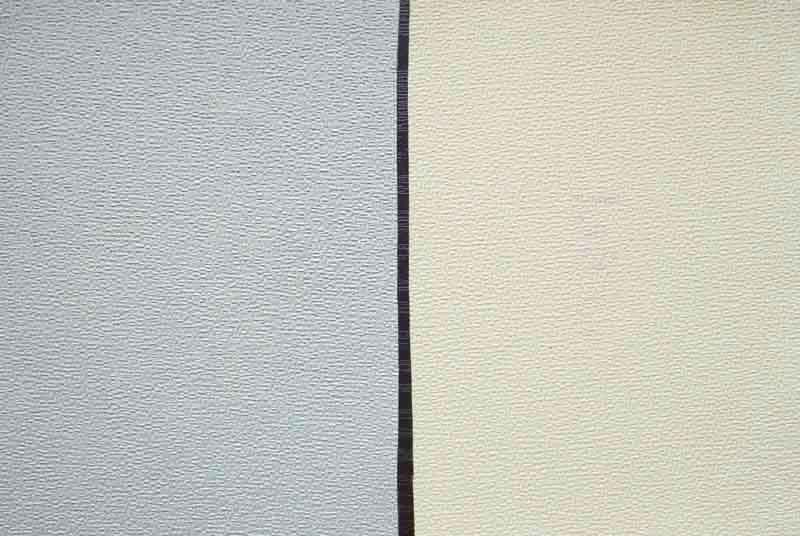 There are two colours - cream and grey, and looking at mine I couldn't tell for sure what I had, but I managed to get a sample of each, to find I had grey. Removing the old is pretty straightforward - one screw with cup washer at the very top, two screws for the rear window latch, three screws for the rear shoulder rail that has to be slid forwards, and five spring clips. On the first side all five of these came out easily, but on the other (only started when the first had been finished) one snapped, and another fell out and hid. The old boards were quite significantly warped, but otherwise in pretty good condition.
 Comparing old and new it is apparent that the size and shape is slightly different, and the foam padding is probably only a quarter as thick on the new. The spring clips lower into holes in the back-board and slide on, and on the old were all orientated in the same direction. The holes in the new boards are slightly smaller than the clips, so the open end needs to be slotted in, then a screwdriver used to open up the end so it can be slid onto the board. I orientated them the same way as on the old boards. I made sure I had clean hands before handling the boards. I was using various tools from time to time during the fitting process, and whilst they are generally 'clean' my hands still get a little grubby from using them, so I kept a man-size wet-wipe handy to use when handling the liners after tools.
Care is needed as the board has to be slid behind the bracket on the hatch opening for the spring stay. The rear edge of the upper half then has to be twisted so that it can sit on top of the rear padded section above the hatch, as will be seen from the witness marks of the old liner, so this is part of the reason for the warping in the old boards. Using the cut-out in the liner that goes round the stay bracket as a guide I peer behind the board to find the lower two clips are nowhere near the holes. I can't move them with my fingers behind the board, so the liner has to come off again to adjust first one then the other of the lower clips, and there are three more to align!
 At this point I realise the new liner is showing the effects of being fitted, removed and refitted behind the stay bracket, so wrap the bracket in masking tape to protect the liner. The upper three clips are more awkward to align - I'm either having to peer down from the edge of the hatch opening through a narrow gap, or outwards from inside the load space, to get a glimpse of the ends of the clips in relation to the holes. I'm also having to push at least one of the lower clips into its hole and unclip it again each time I tweak the upper clips as that is the only way to get a consistent position of the liner relative to the body. There is some up and down flexibility of the whole board, but you have to be aware that the top fixing screw is very near the edge, and in practice the liner has to be pushed up pretty-well as far as it will go. Eventually I get all five lined up, but a couple of the upper three are now sitting in the hole rather than being slid onto the board, and pressing them into the holes in the body is leaving the square imprint of the base of the clip in the vinyl - hopefully that will vanish in time. It's obvious the positioning of the holes in the new liners is perhaps 1/2" different in various directions compared to the old.
There are no holes in the new liners for the top screw or the rear window latch screws, so how you get particularly the former in the right place as there is very little room for error, only a cup-washer? The latch is easier as there is a rectangular plate with two holes, which will give quite a bit of room for manoeuvre. Funnily enough pal Terry had asked me the same question when fitting his early front door liners, which are screwed to the door in the same way, and after a little thought I suggested screwing a self-tapper out from the back, then pressing the board against the sharp point will leave a mark which he could feel and use as a drilling reference. Terry did that, but a couple of them were not accessible from the back, so he took it one stage further and cut the head off, and screwed the shank in from the front, which still left the point sticking out to make the mark. Can't get a screw in from the back, so off with it's head. However it's so near the edge and mixed up with folds on the vinyl and staples that I can't see the mark, so use a blob of pant on the end of the screw instead. For the latch holes position not being critical I use the old liner as a template ... but when I get the liner clipped into position and with the top screw in, despite angling the screw in all directions I can't find the holes. Also even with the screws through the liner only and not through the latch, they are too short for me to be able to see the tip in relation to the hole in the body, to know how far to move the hole. However the screws I had removed from the shoulder rail are about 1 1/2" long, and with those through the liner I can see they are about 1/4" out! Never mind, the latch will cover a multitude of sins, and I can redrill with the liner in-situ. The next problem is that the new liner is about an inch or so away from the body panel, and has to be pressed in very firmly, with a screw through the latch and the liner, wiggling it around to find the hole. Screwing it in enough to bite is proving very difficult, so again I use one of the longer screws to find the hole and pull the liner in to the panel, then put one of the correct screws in the other hole and tighten, then I can remove the long screw and replace it with the other correct screw. Phew, that was a struggle, given the position and having to clamber in and out of the load space all the time, and took about one and a half hours. Still, it's kept me warm in what otherwise would have been a chilly garage.
The second side is much the same, except I opt to mark one of the holes for the latch with the painted screw stub same as for the top, then use the old liner and that hole as a template for drilling the second hole. With one broken and one missing clip I only have three, so opt to use them in the bottom two holes and the middle of the upper three, as the latch and the top screw prove to be plenty good enough for holding it in place. With that and familiarity that one only takes half the time. Step back to appraise my handiwork, looking in from the drivers door to examine it from that angle as well, and immediately espy the errant spring clip sitting on the wheelarch right in front of the seat belt reel, so completely hidden when looking in from the load space. Oh well, I'll keep it in a safe place.
 Then when I lower the hatch to make sure the stay nuts are going to be well clear of the new liners, I suddenly realise that edge-on they are nowhere in sight! As well as being thicker, the old liners sat on the side of the flange around the opening, whereas the new ones are behind the flange. If there was any contact now it would be with the flange before the liners.
 One of the things that put me off replacing them for so long was whether they would look like a diamond in a goat's bottom i.e. make the rest of the trim look really shabby. But I could see from the colour samples that they weren't that bad, and whilst the new liners are cleaner and brighter it's not showing the rest up too badly.
February 2018:
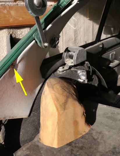 Tom Brearley asked on the MGOC forum about a chunk of foam if found wedged up inside the C-pillar, wondering if it was supposed to be there. It is - but the picture he posted showed his C-post trim with a screw right where the gouges had been on mine. It's a 74 model, but he couldn't say whether the screw was original or not. Clausager shows a 73 and an 80 without it, and my 75 V8 doesn't have it, so it looks as if a PO has added it - either to protect the panel, or because they had removed and had trouble refitting the panel just with the clips! It certainly pushes the panel back out of the way
GT Headlining Added October 2009
 The main headlining on my V8 is not much more than compressed orange fluff about an inch thick - known as 'the biscuit' - with a layer of card between that and the visible vinyl covering. It slides about on the cant rails and is self-supporting. When stripping Vee the mechanic said to be very careful moving it around as they can crack, although whether that was because mine has a glass sunroof to the amount of headliner to the sides is rather narrow, or whether that applies to all, I didn't enquire at the time.
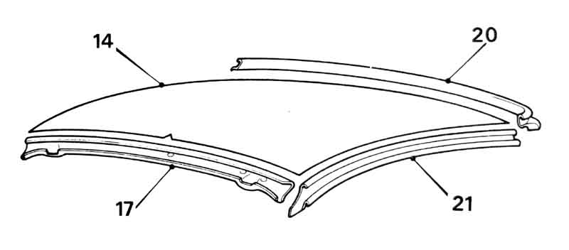 The Leyland Parts Catalogue shows drawings and part numbers for five parts - the main board, the front and rear header rails, and the left and right cant rails. The drawings appear to show that the front header and cant rails are of a similar size and pre-formed type to the rear header, for all eras of GT. I wasn't able to find any reference to the front and side rails from any source, new or used, via Google, and only one to the rear section.
Cutting a panel from sheet is definitely feasible for the main board, recovering kits are available at the rather shocking price of �40-�60. The only other possibility seemed to be breakers and abandoned projects. In jest my pal suggested I take mine out and have a look at it, and was horrified when I said I had already decided to do just that! I then remembered the sun-roof and realised I wouldn't be able to remove the main section to use as a template, but at least I could remove the rear section and have a look around.
 To do that the C-post trim panel really needs to be removed, which involves removing the screws from the rear window catch and another screw right at the top. I then discovered five spring-clips which need careful levering if they are not to rip the hardboard. The plastic covering on the trim panel had pressure bonded to that around the rear window, but peeled apart without ripping with a bit of careful pulling.
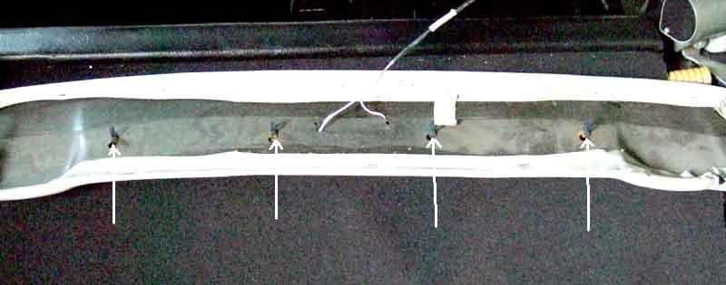 The rear header is a pre-formed, padded and vinyl covered panel attached with two screws through the load-space light plus four spring clips. There appear to be two holes at the ends of this rail for more clips, but only four are shown in the Parts Catalogue and the top of the C-post trim panels support them anyway.
 With the header rail removed it became apparent that far from my 75 V8 cant rails being rigid pre-formed they are covered with the same adhesive vinyl as the main headlining stuck to the structural members of the roof. The front header rail is the same, as the rear-view mirror screws into it with short screws, the edges of the holes being at earth potential when tested with an ohmmeter, i.e. part of the body.
 However Geoff's 78 cant rails are pre-formed plastic, with the frame underneath visible through the mounting hole for the swivelling sun-visors, which use a screw through the mount into a spire clip in a hole in the frame.
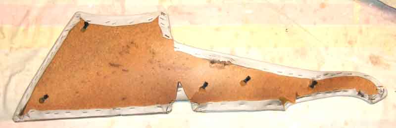
The front and side rails form a 'shelf' running round the roof that the main headlining sits on. A pal managed to get a set of old side and front pieces, which amazingly someone had been able to peel off the body without ripping. Comparing these to the strips in the recovering kit reveals the new pieces to be extremely thin and flimsy by comparison, even taking into account that the originals will have hardened over time and have a coating of glue on them. However I suspect the originals were heat-formed to fit round the box-sections to make attachment easier, and the ends of the front section have stepped ends (also heat-formed) for the ends of the side pieces to sit on, to make a smooth transition from the one to the other.
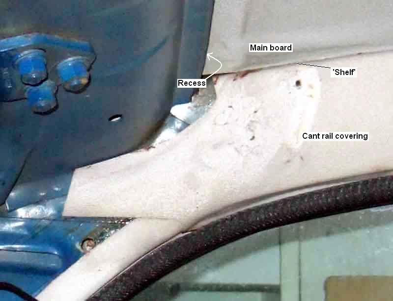
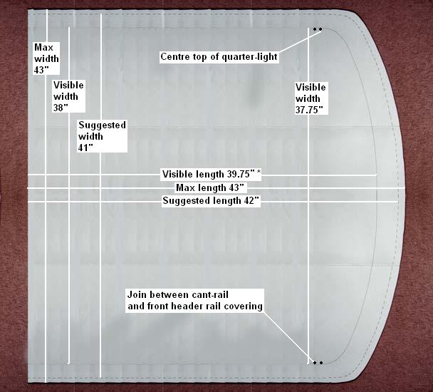 I'd always imagined that the main board just pushes in from the rear above this shelf, the rear panel covering the back edge. The back edge on mine is tucked into a metal recess which is part of the body structure, that may be as a result of having slid back a bit when the sun-roof was fitted, and would need prising forwards and down for removal. As far as cutting a panel to fit goes you wouldn't want to go the full width available above the shelf as I felt various protrusions i.e. reductions in width at various points. Neither would you want to cover less than half the width of the shelf, because if the panel moved over in use it could leave a visible gap, so maybe covering 2/3 or 3/4 of the shelf is the way to go. The amount of board that is 'hidden' above the shelf is surprising - 2" to 2.5" at the sides and just over 3" at the front! However the mechanic stripping Vee said when it is slid fully to one side the other edge drops off the shelf, so it can be removed and replaced through the hatch opening when tilted. But I'm pretty sure I measured the maximum available width at 43", and the visible width at 38", which means the headlining would have to be a maximum of 38" or it wouldn't fit as suggested without bowing, which he warned against.
The maximum size of the tailgate opening at the top is 39", and at the bottom is 41.25". As can be seen above the maximum width available for the board is 43", so some bowing of a board this wide would be required to get it in. Even with a suggested width of 41" it would still have to fed in from quite low down or bowed along its length, and because the highest point of the tailgate opening is lower than the shelf the board would have to be bowed from front to back at the same time. The other issue relates to the upward curvature of the roof. To follow this curve either the board has to have a 'natural' curve produced by steaming or damping and then drying in a mould, or it has to be slightly wider than the maximum available so that the board can then be forced to curve upwards. But that would require a precisely cut board - too wide and it wouldn't go in even bowed up, too narrow and it will flop down again. I don't actually know whether it is a natural bow in the board or a precise width that forces it to bow up, as I say at the beginning my V8 has a glass-panel sunroof the surround of which holds mine up against the roof as well as preventing removal without interference to the sunroof which I'm not prepared to do at this point.
GT Load-space and Rear Seat Back
Luggage cover
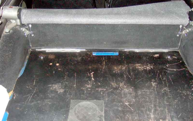
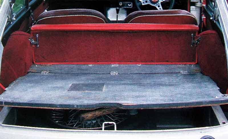 There is a large flat area above the spare wheel and tools which gives a reasonable load space, especially with the rear seat back folded down which extends the flat area. With the additional carpet it is also neat in appearance while empty. Originally there was a two-piece hinged board, with a short section that screwed to the body, and a larger section that hinged up. Simple hinges (AHH 7527) were used here as well as on the seat back, and were screwed to the short section.
 Then in October 1973 the board changed to a one-piece, with more complex hinges (BHH 976, no longer available) that provided the pivot for both the seat back and the board. If needing to reproduce this type of hinge, note that although the pivot and the plates that screw to the board and the seat-back are above the board, additional sections are needed to go down past the edge of the board, then turn at right-angles underneath it to be attached to the body.
Accessing the spare wheel and tool area:
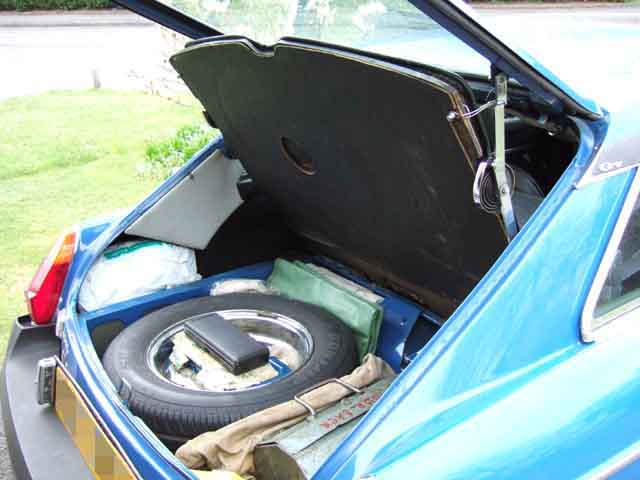 After getting the V8 I very soon tired of supporting the spare-wheel cover on the top of my head when getting tools out of the space underneath - I blame it for my hair-loss ... With the cover raised I noticed that the toggles that fasten it down are very close to the hatch struts and realised how simple it would be to fabricate a simple hook to hold it up. In the end I just formed a piece of stiff wire into a suitable shape and Hey Presto! Click on the thumbnails for a full-sized image.
Luggage Cover: The Navigator has always been bothered about leaving the V8 parked whilst touring as all our worldly goods are on display in the load-space. I've thought about making a cover from a window roller-blind fitted with black fabric and attaching to the top of the rear seat-back, and the free end to a couple of hooks on the tail-gate so it was lifted up out of the way, with the locking mechanism disabled. The MGOC still advertise one in their Accessories Catalogue (Part No. E015) at �55 but apparently it hasn't been available for some time. Too pricey for me anyway, and it doesn't lift with the tailgate. I think they also sell a hard moulded cover, like many modern cars have, but at some huge price several times that of the unavailable cover. Not only is that less convenient as you couldn't use it with anything that sticks up higher than the top of the rear seat, but if I were going down that route I think I'd be looking for one off a similar sized car at a scrappers even if it had to be trimmed a bit.
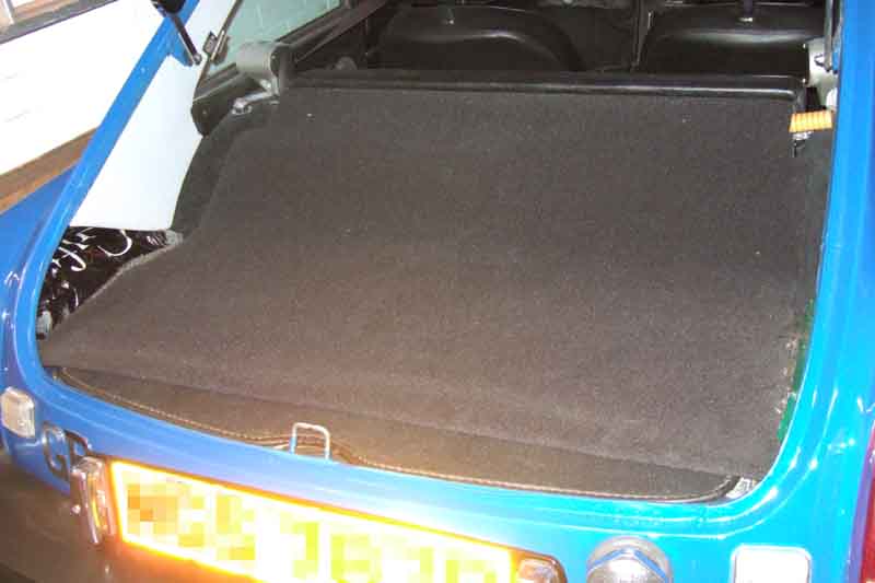 Then one trip away I had the idea of putting the load-space carpet over the luggage instead of underneath it
and that together with the tinted windows meant you had to look pretty closely to see anything. The only drawback with that was that the luggage then slid about all the time on the shiny spare wheel cover which was irritating. However it gave me the idea of getting a piece of carpet to do the same job. Next Stoneleigh MG Spares Day I spotted someone selling load-space carpet quite reasonably at about �15, but also selling sheets of carpet a couple of metres square for just �10,
so I got myself one in black. It was described as 'Volvo quality' but was significantly inferior to the load-space carpet from the same vendor and other carpet squares from other vendors, but as it wasn't for 'walking' on and only a load-space cover I reckon it will do just fine. It will also allow me to make one long enough so that with the back seat lying flat with large loads I can still cover it all.
Then one trip away I had the idea of putting the load-space carpet over the luggage instead of underneath it
and that together with the tinted windows meant you had to look pretty closely to see anything. The only drawback with that was that the luggage then slid about all the time on the shiny spare wheel cover which was irritating. However it gave me the idea of getting a piece of carpet to do the same job. Next Stoneleigh MG Spares Day I spotted someone selling load-space carpet quite reasonably at about �15, but also selling sheets of carpet a couple of metres square for just �10,
so I got myself one in black. It was described as 'Volvo quality' but was significantly inferior to the load-space carpet from the same vendor and other carpet squares from other vendors, but as it wasn't for 'walking' on and only a load-space cover I reckon it will do just fine. It will also allow me to make one long enough so that with the back seat lying flat with large loads I can still cover it all.
GT Rear Windows October 2017
These were originally chromed brass, changing to stainless in May 1972 (some 5000 cars after the quarter-light were changed).
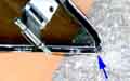 Probably as part of this change the rear lower corner of the window was redesigned from having a join to being a continuous curve, and a trim-piece added to fill in the resultant gap to the body. The hinges, catches and B-post trim strip also changed at this time.
The earlier hinges were handed, and seem to have been full-length - one per side - probably similar in design to piano hinges, and probably in brass or chromed brass. The later stainless windows had a much simpler system which was just a rectangle of thin stainless steel bent into a 'U' shape (BHH698), as the amount of movement at that end between open and closed is negligible. Two per side, and they are not handed. What follows relates to the later design.
 I removed these as part of Vee's restoration. Quite straight-forward - remove the screws holding the catch to the C-post at the rear. Pull the door seal away from the flange and you can get at the screws that hold the B-post trim strip on. With that off you can remove the screws that hold the hinges to the B-post. Replacement is inevitably the reverse.
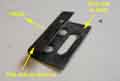 One of the hinges on the off-side was detached from the frame - I think the rivets had pulled through the hinge and were still in the frame. I've replaced a hinge on a front quarter-light opening vent, and that was quite easy, just using an ordinary pop-rivet. However the folded-over shape of these hinges means that at the very least you would need a tool with a long tubular nose, and possibly a rivet with a longer shank, to get across the folded-over part. There may also be a problem in getting into the frame, I can't recall. If replacing them, remember that the curved part of the 'U' of the hinge goes towards the inside, and the open part towards the outside!
Alternatively you might be able to do what has to be done when replacing the front vent hinge-pin, and that is to remove the glass from the frame, in order to put a screw through from the inside, and use a nut on the hinge. Bit trickier with the rear window, though, with the frame going all round the glass as it does. As I never open the rear windows, and the other hinge was fine, I opted to leave it alone. If both hinges were suspect though, there is a risk that air-pressure would blow the window out.
 Corrosion of the lower leading corner angle bracket is not unknown, Sven Hinrichsen from Germany took a series of photos of the repair he carried out.
January 2023: The stainless steel frames are assembled with pop-rivets but the earlier chromed brass use screws. Not listed in the parts catalogue or by the usual suspects Brendan H on the MGOC forum got some from Martin Williamson and confirms they are 6-32 x 1/4" UNC stainless steel countersunk Phillips machine screws. The glazing seal changed with the frames, and although said usual suspects specify the later pre-formed rubber seal is suitable for all years it isn't, probably because the chromed brass material will be thicker than the stainless hence a smaller channel in the brass. Might be worth trying the QL vent glazing seal 27H8705 which is flat rubber strip, or maybe Woolies 88-2-1/32 which looks thicker.
Hardtop Added January 2010
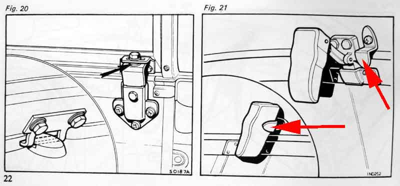 Original accessory as well as quite a few after-market variations, each with their own parts for glazing and seals, but the method of attaching to the car should be common so that's what this section is about.
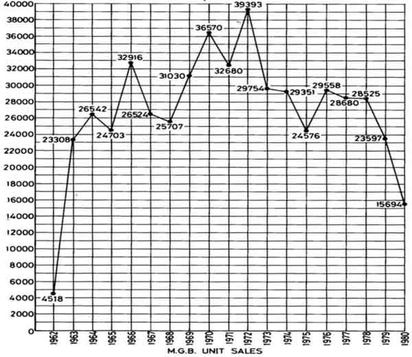
See also this price information.
Clausager has much information on this in his book, but for some reason omits the total numbers for each market for the basic roadster and GT, even though he includes them for the MGC and GT V8. They are as follows:
| RHD Home | RHD Export | LHD North America | LHD Other Export | LHD Sweden/ Germany | LHD Japan | RHD CKD | LHD CKD | Total | |
| Roadster | 49699 | 6507 | 298052 | 19217 | 1929 | 1379 | 9278 | 900 | 386961 |
| GT | 64980 | 6989 | 47188 | 4889 | 916 | 0 | 216 | 104 | 125282 |
| Total | 114679 | 13496 | 345240 | 24106 | 2845 | 1379 | 9494 | 1004 | 512243 |
And whilst on the subject of numbers, see this info on how many UK cars are still currently taxed or on SORN with the DVLA. It's interesting to see from the DVLA figures the effect of the reintroduction of the rolling 40-year Historic classification and zero-rated road tax, particularly for the V8.
 There is a steady decline in licenced cars from a peak of 712 in 1994 Q4 to 323 in 2014 Q1. However in 2007 Q4 SORN figures come into play and a period of significant 'winter SORN summer licenced' switchbacking begins, with a continuing decline in the 'licenced' peaks and increase in the 'SORNed' peaks with 2013 Q4 showing 535 SORNed and only 347 licenced. However after that and as the Historic classification kicks in the picture changes and there is a steady rise in licenced V8s and a corresponding drop in SORNed until 2019 Q3 when there were 696 licenced which is almost back to the 1994 Q4 level of 710, and only 274 SORNed, and nearly 1000 out of the original 2591 still 'on the books'. Since then the number of SORNed has remained fairly static, and the number licenced dropped back to 680, indicating that either some have been scrapped, or more hopefully exported. What is particularly interesting is that when the SORN system arrives in 2007 Q4 the number of licenced cars only drops by 8 from the previous quarter, but suddenly 418 SORNed cars appear, perhaps having languished untaxed in garages and barns 'awaiting restoration' for decades. Comparing 2008 Q3 i.e. the first summer in the SORN system to the present day there were 282 SORNed then and 276 now, so very nearly the same number still waiting! To me that is a surprisingly large number.
November 2023: From a peak at 14156 roadsters Licenced in 1994 Q4 (from when records were first available) there was a slight decline to 11898 in 2013 Q3 but by 2023 Q2 that number had gone back up to 14,111, almost exactly the same as the previous peak. This is plus 4756 on SORN. By contrast GTs were at 19498 in 1994 Q4 (i.e. more GTs than roadsters) but then began a steady decline to 8643 by 2013 Q2 (i.e. significantly less than half) with an almost equal number on SORN, then only a slight recovery to 10774 in 2023 Q2 plus 7768 on SORN. V8s were 710 in 1994 Q4, falling to a combined total of 822 in 2013 Q1, then a recovery to 739 Licenced in 2023 Q2 plus 248 on SORN. V8 figures are complicated by engine conversions as above.
Originally, very strong. But the bulk of the strength is in the sills (just open both doors, squint through the gap and see just how little metal is joining the front and the rear of a roadster together!) and chassis rails and corrosion of the former at least is very common and weakens the structure to such a point that it sags and the bottom of the doors can rub on the tops of the sills. In this state the body is very weak indeed and you could get significant crushing of the cabin space in even a relatively minor impact.
 This from MGBs Made in Australia.
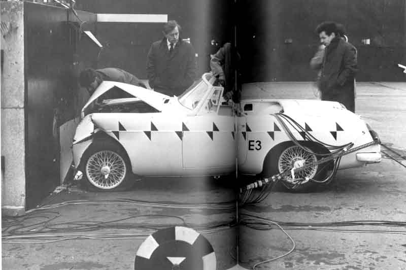
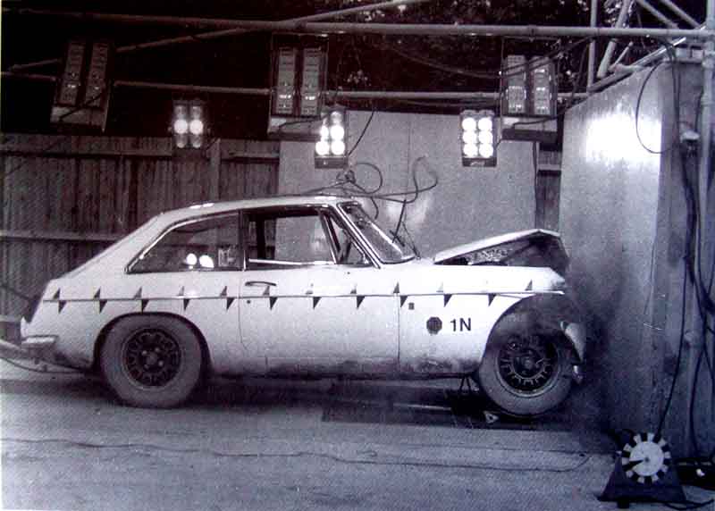 But going back to the original strength Abingdon were carrying out impact tests in the 60s and 70s, pages 216/217 of 'MG by McComb' and 142 of David Knowles's 'Untold Story' showing the results of just such impacts into a concrete block at 30 mph by a roadster and a GT. Even now Euro NCAP only tests at 40mph (albeit as a partial frontal and not a full frontal as this is) but the damage is usually much more severe than this. Apart from the crumpled bonnet there appears to be no damage behind the front arch.
BMC crash tests a Mini, 1100, 1800 and at 9:33 an MGB. From underneath at 10:48, and steering wheel intrusion at 11:58.
See also this factory video of a test of air-bags in an MGB.
There is also this well-documented case of an MGB at Silverstone hitting a concrete barrier at an estimated speed of 90mph and experiencing a deceleration of 75G in not much more than a couple of feet. The driver was unconscious but this was from the effects of deceleration, not impact of his head with any object. And although the driver suffered a broken bone in his foot this was purely from the force of his foot flying forwards and hitting the toe-board or pedals, there was no intrusion into the footwell.
 Modern cars have carefully designed crumple-zones at the front and the rear to give a more gradual deceleration than the Silverstone case, and a strengthened passenger 'cage'. However this means that even in relatively minor accidents the crumple zones will be deformed to the point where the car is declared a write-off (although there is a legal cottage industry specialising in the repair of many of these). Also, and more importantly, above a certain impact speed the passenger compartment will crumple like tin-foil. This is obviously an extreme case, and the fact the 'other vehicle' was a truck doesn't help, but remember the next time you are bowling along a single carriage-way, that even at legal speeds your closing speed with someone coming the other way is 120mph.
 And nothing is going to protect you (short of a tank) if you pull out of a side turning while talking on a mobile phone.
Identification Numbers (was 'Body Numbers') Updated May 2010
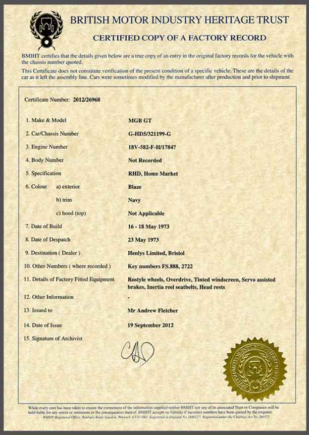 Get a Birth Certificate for your B (and other MG models and marques), direct from The British Motor Museum.
Body Numbers
Chassis Numbers
Commission Numbers
Replacement ID Plates October 2013
Australian CKD MGBs
Body Numbers:
Clausager has quite a lot of information on this, but not entirely correct as we shall see. To summarise his information:
- MGB roadsters originally had two body numbers.
- One with no prefix, starting from '1', stamped into a steel strip, spot-welded to the inner wing behind the radiator on the dynamo side. This number was written into the Abingdon records.
- The other with an 'MGB' prefix, starting from '101', stamped into an alloy strip, screwed to the inner wing by the carbs, not recorded by Abingdon.
- On Mk2 roadsters (but see below) the MGB tag moved in front of the radiator, still on the carb side, riveted in a vertical position. Rubber bumper prefixes changed to GB23T for RHD roadsters and GB23D for RHD GTs.
- Mk2 roadsters for North America had body tags prefixed MGBU, those for Germany and Sweden from 69 to 74 were GBSN, and both had their own series of numbers. Rubber bumper prefixes for North America changed to GU23T for roadsters and GU23D for GTs (only 1247 North American rubber bumper GTs as they were only produced through the '1974 1/2 model year' period).
- From 1969, roadsters with Swindon/Cowley bodies just had the MGB tag, which was now the one recorded by Abingdon until 1972, after which body numbers ceased to be recorded.
- GTs and V8s had different prefixes - GBD for the chrome bumper 4-cylinder cars then GB23D for rubber bumper, except GBDU for Mk2 for North America, GBSD for Germany and Sweden from 1969, and GB75D for the V8, each with their own number series.
- Until GT production started body numbers stayed pretty close to chassis numbers, for example Clausager dates chassis number 66580 to July 1965 and body number 66808 to August 1965. With the separate series for GT, North American and Germany/Sweden, but all cars using the same chassis number series, they got further and further apart.
- Rubber bumper cars had the body number on a larger strip welded into a depression on the bonnet slam panel.
- Australian CKD cars were very different in several aspects.
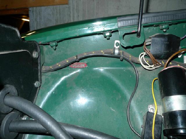 However going by actual examples it was sometime between April 65 and October 66 that the 'MGB' tag moved to what Clausager says is its Mk2 position, and almost certainly at the same time the unprefixed tag also moved, to the very front edge of the inner wing on the dynamo/alternator side, orientated vertically, between two bolts for the outer wing. GT production started in September 65 so it's possible that was the actual change point. There does appear to be an example of a one-owner, unrestored (going by its present condition) 63 roadster that has the MGB number but not the other one.
Why two body numbers? Some cars (MkII roadster bodies built at Coventry) - could have four tags - two body number plus the Commission and Chassis numbers. MGBs were built in at least three plants, possibly four, being shipped between them so some means of keeping track at each stage was required. The spot-welded, un-prefixed, steel tag was almost certainly attached during body assembly, certainly before painting. As the MGB-prefixed tag was originally screwed, but also painted, it was probably attached at the paint and trim plant i.e. at the next plant in the sequence. This could well explain why the two numbers could drift apart, for example a 1966 example has its two numbers over 500 apart. The Commission number plate was riveted to painted bodies i.e. at the trimming stage before shipping to Abingdon. The Chassis number plate was riveted by Abingdon after final assembly. This still doesn't fully explain two body numbers, but there must have been a reason, they wouldn't have done it just for the hell of it, it's simply lost in the mists of time.
Not strictly identification and Clausager doesn't mention it, but earlier bodies seem to have a Pressed Steel Fisher patent plate spot-welded onto the shelf between the battery cover and the left-hand arch, from comments it seems to have vanished sometime between 1970 and 1972. Clausager says that body production moved from Swindon to Cowley in 1970 which could be when it stopped, but an example from a 1970 is stamped COWLEY. On the face of it that seems to indicate they were still being fitted at Cowley, but then one example from a 64 is also stamped Cowley when Clausager says they were being made at Coventry! Another example was attached upside down, maybe by a disaffected employee.
Chassis Numbers:
Similar confusion over the plates for these, it seems. From Clausager:
- "Until January 1967 a small rectangular plate with the MG octagon logo was used", and his pictures shows them stamped from the front.
- "In January 1967 a new type of plate, rectangular with rounded ends, headed The MG Car Company, also used on MGCs". The statement has been made that this was also front stamped, but his picture appears to show it as rear stamped. Also the credits indicate this is a 69 model, and Clausager says that plates were screwed until 1970 then pop-riveted, but this MGCs plates are pop-riveted.
- For UK cars, "In the autumn of 1972, and certainly on all cars from January 1973, the name of the manufacturer was changed to 'Austin Morris Group', also used on the V8, and this style was used until 1979", and his picture (74 V8) shows this reverse stamped.
- Also for UK cars, for the final year of production a deeper, square-ended rectangular plate was used, headed "BL Cars Ltd.", and with paint and trim codes included. Clausager shows this as front stamped.
- For North American cars a second strip-plate was introduced from 1st January 1969 viewable through the screen from outside the car, and from September 1969 a special identification plate was introduced riveted to the shut-pillar of the left-hand door. Originally "The British Motor Corporation Ltd.", the company named changed to "British Leyland (Austin-Morris) Ltd. in 1970, and in 1972 to "British Leyland UK Limited"
All fair enough, but there has been a statement that the direction of stamping changed in the autumn of 1972 along with the plate type. However 73 model-year cars started to be manufactured in August of 1972 with chassis number 294251 for roadsters and 296001 for GTs, and my September-72 built 1973-model roadster has the MG Car Company plate (i.e. the old one) stamped from behind (i.e. the new way). So the direction of stamping changed before the plate type, which could have been as late as January 1973. I've pondered the possibility of both types of plate being used for a while during the cross-over period, as parts sometimes were. But that would mean two or more people stamping them, probably in different locations, which seems very unlikely, given the need to avoid any possibility of stamping the same number more than once.
Moss Europe also causes confusion by stating the UK plate changed from 'MG Cars' to 'Austin Morris' in 1970. The North American plate did change in 1970, so either it is a typographical error or they simply assumed the date of the change was the same for both markets. All the other evidence points to the UK plate not changing until after the start of 73 year model production.
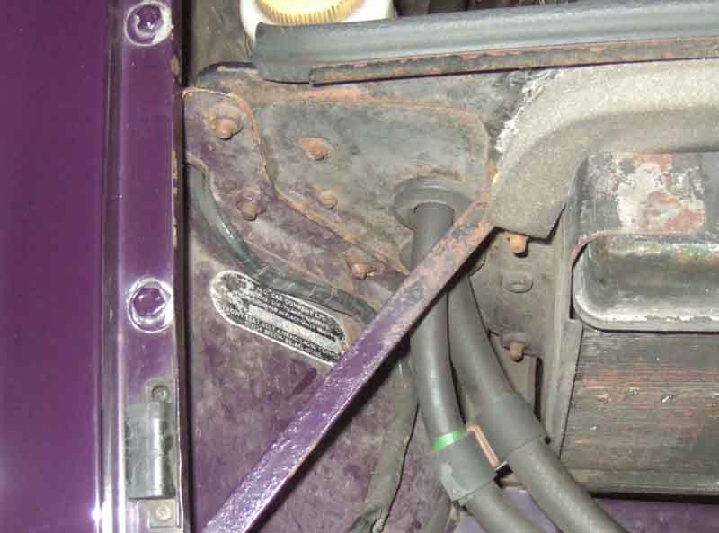 What doesn't seem to have changed much is the fitting position. Clausager implies that until the final year of production 4-cylinder cars plates were always on the right-hand inner wing (on the left as you look in from the front), just in front of the radiator. The final year used a larger plate on the same side of the bonnet locking platform. The MGC chassis number plate seems to have been on the left-hand inner wing (i.e. carb side) behind the radiator. V8s are immediately behind the oil filter.
 I've never seen a picture of a Chassis number stamped into the body of a UK-built car, and Clausager indicates this is a very confused and uncertain feature. However he states (p151) "October 79 VIN number now stamped in right-hand sidemember of boot floor on all cars" and Maurice Irwin says his 1980 GT has "a stamped number on the top of the rear offside chassis leg, just under where the boot floor board is". Australian CKD cars had a special (BMC Australia) plate with the body number as a suffix to the chassis number, as well as the engine number and body colour. On an example of a Mk2 this plate was on the inner wing in front of the radiator by the oil cooler pipes. The body number was also stamped into the actual shell, just behind the opening for the pedals on the carb side in one case, beside it in another, and the chassis number was stamped into the top of the carb-side chassis rail at the very front. There also appears to have been a 'diecast' plate behind the wiper motor giving the date the kit of parts was put together, presumably supplied by Abingdon, the actual build date being later of course.
Commission Numbers:
Much less confusion over these ... but still some. It seems these were generated from the beginning of production, but Clausager states they were only attached to vehicles with the start of MkII and MGC production in 1967 - to the bonnet-lock platform of MGB and GT V8, by the chassis number plate on MGC. They continued to be generated and attached to vehicles until at least June 1976, but Abingdon stopped recording them in April 1971. This would be the only place off-car they were recorded, so if yours is lost you should be able to retrieve it from The British Motor Museum records at Gaydon if manufactured before April 71, but not afterwards.
Replacement Identification Plates
November 2016: I've just been made aware of the full range of identification plates available from MiniMail, covering B-series engines as well as A-series. Far more comprehensive and with more background information than any of the other sources.
October 2013: I note that some of the usual suspects have decals and blank identification plates of various types. Moss Europe seems to have the full range of chassis number plates but for some reason commission number plates for 62 to 69 Coventry-built roadsters ('F' suffix) and 70 to 76 Cowley built roadsters and GTs ('Z' suffix) only, and not for Swindon built 69 and 70 roadsters or GTs up to 1970 ('P' suffix). SC Parts have 'P' GT plates as well as 'F' and 'Z' roadster plates. Moss US has two types of commission plate - for what they describe as '68-69' and 'Roadster, 70 on' at almost twice the price of the first one, but the image shows one completely blank plate. Completely blank plates are also available from a Mini supplier on eBay, but you would need to confirm the size is correct. You could get an 'incorrect' plate and remove the screen-printed suffix - or a blank plate, then stamp or engrave and paint-fill the correct suffix.
For stamped plates I'm aware of three sources in the UK - and for the chassis number you will usually be required to send the old plate if legible, or a copy of the V5 registration document showing the same name and address as the delivery address: Welsh MG who can supply the plate as well as stamp it, Retro Minis and Classic Plates, plus Clarke Spares and Restoration in the USA. However Classic Plates require you to supply the correct screen-printed blank for chassis and commission plates, and although they say they can stamp plain alloy e.g. for the engine number which you could then cut to size and punch the holes, when Bill Etter contacted them about an engine number tag they didn't offer him this option! Retro Minis have blanks of screen-printed and engine number tags, and the rivets, although whether they are the correct size and format for MGBs is another matter. They give the dimensions for their engine number blanks but comparing them with my 18V their overall length and rivet spacing is slightly bigger, which is perhaps a little odd given the Mini A-series engine is smaller than the MGB B-series:
| Dimension | My 18V | Retro Mini | Note that for rivet spacing Retro Mini state: "holes on drilled at 2.64 inches 67mm centres" in addition to "holes 2.49 inches 63.1mm apart", I don't know why. |
| Length | 3.08 | 3.24" | |
| Width | 0.59" | 0.490" | |
| Rivet spacing | 2.45" | 2.49" |
Moss US have engine number blanks and rivets available, but indicate the plates are only suitable for 18G to 18GK engines.
All three stamping sites show embossed i.e. reverse stamped to give raised characters. However original plates varied as to whether they were impressed or embossed according to plate type, market and year, although engine numbers may have been embossed right through.
January 2016: Classic Vehicle Spares have (albeit listing ended) engine plates for what they say are MGBs up to 65 (however the 18GB ran from late 64 through to late 67 and Moss US indicate the same plate is suitable for all 18G engines i.e. up to March 71) but don't state the size although they may well respond to a question. They also have a stamping service at �10.10, which appears to show impressed characters, not embossed.
Character size also varies. Bill Etter was told by Classic Plates in his enquiry about an engine number plate that they use 5/32" stamping. However mine measure 0.193", which given that the raised characters on the plate will be slightly larger than the embossing on the die, probably equates to 3/16" or 0.1875", which is the size on another engine with an original plate that Bill has. It's also the size that Clarke's use, although Bill finds the spacing on one of theirs he has is too close compared to his original. I then checked my chassis number plate, and although embossed as well they are smaller at 0.170" which is closer to 5/32" than 3/16". No doubt a factor of engines and bodies being made in different places since time immemorial.
April 2014: Bill got his plates back, nicely stamped. However to get all the characters in they used a longer blank than the ones that Bill had provided so now it won't fit the engine! There is also the question of whether hyphens and slashes were used. Bill's contain hyphens, as Clausager shows them (although he shows one after the '18V' as well). Even when slashes between the prefix and the serial number weren't used there was a space, and where slashes were used these have occasionally been interpreted as a '1' by the DVLA.
I've also just discovered that apparently Australian CKD cars had the tag removed and the number stamped directly into the block. V8s are like this, but then they have an alloy block. How hard the stamp had to be hit to make an impression in cast-iron, and how long the stamps lasted, can only be guessed at. Or maybe they were engraved, the information I read used both terms.
Jacking September 2019
Wheel removal
Herb Adler's jack storage bracket
Safety First 1: Never work with any part of your body under the car when it is supported solely by the jack, always use axle stands or drive-on ramps. For that matter I would never use four axle stands i.e. one at each corner as I'd be concerned about pulling the car over. When using a combination of wheel ramps and axle stands wherever possible put the rear wheels on the wheel ramps with the handbrake on for the same reason.
Safety First 2: I've read that unless your car has had full replacement of the sills in your ownership, to the correct standard and with appropriate corrosion protection, you should never rely on the factory jacking point even to change a wheel. Linton Husband reports on the MGOC forum that as a trainee mechanic at a BL garage in the 70s they were told never to jack an MGB using the factory jacking point, always separately at the front or rear. Bee had sill replacement before my time and I did try using the factory jack when I first got her, but the creaking convinced me to go no further. As part of the restoration and repaint I did ponder replacing them, but as externally they showed no corrosion I decided to leave them until they needed doing - that was 30 years ago! As well as sills collapsing the ends of the chassis outriggers that the jacking tubes are welded to can rot and the tubes tear off, there are short and long repair sections for these as well as the tubes themselves from the usual suspects. I keep a scissors jack, wood block and a telescopic in Bee (which leads me onto the 'Tip' below) and a 2 tonne trolley jack in Vee, but for long journeys Bee gets the trolley jack.
Safety First 3: If you jack under the rear of the car or use the factory jacking point, make sure the front wheels are chocked. A pal had his car roll when raised on the factory jack and it speared into the sill.
Tip: When using an alternative to the factory jack make sure that it will lift the car high enough to remove a wheel with a flat tyre and fit an inflated one - I speak from personal experience! Bee's telescopic jack was fine for raising the car enough to remove wheels for cleaning, but one day bringing her back home from the remote garage I had a rear puncture. With the car lower I couldn't unscrew the lifter from the telescopic part as far as usual, so the full extent of the hydraulics wouldn't lift the car enough to get the wheel off. I was just pondering using the spare as an interim support somewhere while I lowered the hydraulic, unscrewed it some more, and jacked up again, when another MGB happened to pass and we could use whatever jack he had (also not a factory jack) to raise the car enough. I say 'pass' but I was in a residential side road, he was driving past the end of the road a couple of hundred yards away and just happened to look down the road! You have been warned. Hence why Bee now carries a screw and a telescopic - tested! - unless we are on a long trip with the trolley jack.
 I've also extended the crank handle of the scissors jack by 15" so I can jack from the ends of the car (the wheels being in the way of jacking from the side) without having to crawl underneath.
Also when using an alternative jack you need to consider carefully where they are going to be positioned. At the front under the spring pans will raise one corner to remove a wheel. To lift the whole of the front of the car the centre of the cross-member can be used, but the jack needs a raised tab positioned behind the cross-member or it will slide forwards as the car is raised. I would never jack under the chassis rails at the front of the car for the same reason - as the car goes up the angle to the horizontal increases, again with the risk of the jack slipping forwards. If working on the car axle stands should be placed under the spring pans, or under the brackets that attach the A-arm mounting points to the cross-member if working on the suspension.
At the rear I jack under the rear spring front mounting point in order to remove a wheel on Bee as when jacked under the axle the wheel is tucked up inside the arch and cannot be pulled off the hub. Under the body needs more jacking as the axle and hence the wheel drops as the car is raised of course. For Vee with the higher ride height I can jack under the U-bolt plate which lifts wheel, axle and body together and the wheel can be pulled straight off. Sometime I have jacked under the spring itself, but only ever the front half i.e. in front of the axle. If you jack under the rear half the jack can slip as the car is raised and the angle of the spring to the horizontal increases. Jacking under the axle tube near the wheel is also fine, if working on the spring. Or under the diff casing to raise the whole of the rear, but care needs to be taken in placement so it cannot slip, and again axle stands should be used once raised. Also I err on the side of caution and don't 'bounce' the car on the jack when lifting by the diff casing, i.e. lift slowly and carefully as it's putting much more stress on the axle tubes than jacking by the wheel, or in normal driving.
All the above is written with the best intentions but is subject to Errors and Omissions Excepted, i.e. I will not accept any liability for anything you may or may not do or cause, YOUR safety is YOUR responsibility.
 Clausager describes three different jacks supplied with the MGB over the years: He says a red 'King Dick' was supplied originally, a stronger blue type 'from the same maker' in May 73, and a black Metallifacture jack from Feb 74. However in depicting his three jacks the foot of the red one is significantly different to the other two - the blue and black being the same. I have blue and black jacks that came with my cars, although which jack came with which car I can't remember, let alone know if they were original to the car. As Bee was built in September 72 then maybe she should have a red one. I'm also doubtful about the change in maker as my blue and black jacks are pretty-well identical in terms of the component design and assembly method. Another poster on a forum has the same construction of blue jack as mine with covered gears, whereas Clausager's blue jack has exposed gears. There are other differences as detailed by clicking on the attached thumbnail.
Fixed cross-member and jacking points: July 2021
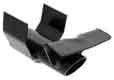 The fixed cross-member carries the factory jacking points and runs the full width of the car. I have seen (somewhere) factory or workshop instructions that say not to use the factory jacking point if the car is more than five years old and the condition of the sills is unknown. Ex mechanics have also said that in their workshops they never used them, regardless of age or condition. The outer ends of the cross-member rot over time but repair sections MB31 are available, as are longer 'half' sections HZA464H, and the jacking-points themselves HZA492. The central section wouldn't normally need to be replaced given the amount of oil and grease that seems to collect. If you look at a complete crossmember HZA464 it is an open channel and not a box-section, but if you feel above the crossmember in the tunnel it seems to have a 'lid'. This lid is in fact a strengthening/reinforcing piece that is welded between the two sides of the tunnel and I suspect was more about preventing the tunnel from deforming before it had the other panels welded around it in the factory, than preventing water, dirt and salt from entering the crossmember - enough of that happens from the open ends.
Wheel removal: For the reasons above I've never used the factory jacking point, and have a small trolley jack when doing any work on the car - with axle stands when in the garage, carry that trolley jack round when travelling long-distance, and keep it in the V8. For local journeys in the roadster I keep a small hydraulic bottle jack in the boot and that is enough to change a wheel ... however! When I had a puncture, because the car was lower and I couldn't screw the lifting pad out as far as normal, it wouldn't lift the car far enough to get the wheel with the flat tyre off and the spare on! I was just pondering if I could use the spare under the car somewhere to hold it up a bit while I repositioned the jack to raise the car higher, when an MGB happened to drive past the end of the road and the driver spotted me. He turned round and drove up, and with his jack we managed to do the job. Lucky or what? The roadster came to me with a scissors jack, which needs to be on a block of wood to raise the rear of the cars high enough to get an inflated wheel off, but again won't work if the tyre is flat. So now I carry both jacks plus the block of wood in the roadster - having tested them with a flat tyre - unless we are going long-distance when the trolley jack replaces the bottle jack.
A tip from Stephen Strange when removing a rear wheel, particularly on a chrome-bumper car with centre-lock hubs. If you jack under the axle as would normally be the case the tyre will go up into the wheel well even more than it may be already. You can jack under the spring front hanger but will have to jack much more to get the tyre off the ground. You can jack under the spring between the axle and the front hanger, but only ever with a jack that has a claw-type lifting pad that can fit round one of the clips that holds the leaves together. But whether that is good practice is debatable as it may distort the spring. Don't jack under the rear half of a spring even under a clip as the angle will change and the jack has a good chance of slipping. Never jack just under a leaf as the risk of slipping is too high. Stephen's alternative is to have a block of wood handy that just fits between the bump rubber and the bump stop, then as you jack under the axle the block of wood will lift the body at the same time that the jack is raising the tyre off the ground. However even this may not be enough to get a centre-lock wheel off a CB (or lowered RB) car if the tyre is already tucked up into the arch when on its wheels. You may need to fashion a block that fits after the body has been raised a little so the tyre clears the arch, then you can jack under the axle. Don't forget to take the block out before driving off ...
Adjustment
Repair
Door/wing mirror provision was pretty variable over the years, originally optional unless a boot rack was fitted, then when standard sometimes one and sometimes two, and with the North American recessed or 'fishmouth' grille a door mirror on the driver's side and a wing mirror on the passenger's!
Positioning: May 2021
Following a question on the MGOC forum about position because someone of 6' 2" height found he was having to duck and lean. I used to be 5' 11 3/4", probably shrunk a bit now. With the roadster hood up I do have to duck my head a bit to look out of the driver's side window at something higher up because of the hood flap inside the drop-glass, but not the mirrors. New seat foams as supplied will make that effect worse, mine are originals in both cars.
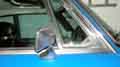 The V8s are positioned so that the bulge on the back of the mirror very slightly overlaps the drop-glass channel when looked at square-on from the side. Rotating my head both are in full view, no dipping or leaning.
The roadster ones are slightly further forwards as I used them and a backing-plate inside the door skin to strengthen the skin after a Crack of Doom repair. For that reason they do obstruct full opening of the vent, but who needs vents in a roadster? Even with the hood up the driver's side is in full view, the passengers slightly obscured by the drop-glass channel, but it's never been an issue.
Adjustment: I find most people adjust these so they can see more or less the same as in the interior rear-view mirror which includes quite a chunk of the side of the car. As someone else almost said "If you are in the car you should know the sides are there even if you can't see them". I have mine adjusted so that by moving my head one side or the other from my normal driving position I can see the sides of the car for manoeuvring, but not in normal driving. This means that the rear of even small cars is still visible in the interior rear-view mirror when the front appears in the side mirrors, and is similarly visible in the side mirrors when the front appears in my peripheral vision, and should be to most people when glancing in the side mirrors. Close Encounters not-withstanding you should also be regularly checking the internal rear view mirror for people coming up behind you, including other lanes of multi-lane roads and it shouldn't normally be a surprise to see someone for the first time in a side mirror, or your peripheral vision. But of course other drivers can often do silly and unexpected things which is why you do need side mirrors, and need to use them before indicating to change lanes or overtake. FWIW I also glance to the appropriate side before changing lanes as well, there is always the chance that someone on a uni-cycle is about to overtake you.
If that isn't enough you can get small, convex stick-on blind-spot mirrors that can be attached to a flat-glass door mirror e.g. as here. They are called 'blind-spot' mirrors but some of them are so convex that you can see almost as much as in a flat mirror, but everything is made exceedingly small. They should be fitted to the outer upper corner of standard mirrors. And of course most cars these days come with the outer edge slightly convex anyway so don't need them. My Toyota came with one on the drivers side, but I took it off as adjusted as above I found I didn't need it and it just reduced the clarity of what was in the mirror.
Recently someone took the rather superior view that Americans always have their mirrors adjusted correctly as they can be passed both sides. For a start what is important is to be sure there is no one in the lane you want to move into before you move into it, which side you can be passed is irrelevant. But Americans have those annoying 'bifocal' door mirrors, which are fitted precisely because they are no better at adjusting their mirrors than anyone else, and nanny state has decided to intervene. These mirrors use a convex lens effect on the outer portion so that even when they are adjusted such that the plain part shows what is behind the car the convex part shows what is on the rear quarter. Hopefully. Of course that gives a distorted view across the mirror as a whole, so they also need to be shouted at with 'OBJECTS IN MIRROR CAN BE CLOSER THAN THEY APPEAR'!
Door mirror repair: April 2019
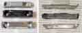 Walking round the car during servicing I was vaguely aware I had bumped the passenger side door mirror slightly but didn't take any notice. The when reversing her back into the garage noticed the mirror was too high, went to adjust it, then discovered the whole mirror was tilted back as the rear edge had become detached from the 'wedge' and plinth that is screwed to the skin. Lucky it hadn't fallen off, as I broke one that way many years ago. The taper at the rear edge of the plastic wedge had broken off, and in fact when unscrewed it fell apart into several pieces ... there was a clatter as something fell down inside the door ... and I remembered that 30 years ago the holes in the passenger skin were too big to grip the plastic pins of the plinth when the screws were in, so I had to make a plate that the screws could go into more firmly, and it was that which had fallen down. So waist-rail, pull-handle, window-winder off and trim panel removed to retrieve the plate. The wedge is quite a simple shape and I reckoned I could make one, but did some Googling and found repair kits for TEX mirrors such as this M99985. But is it the right size? Also I only need the block, �6 seems expensive for that, and it's still plastic.
 I have a sweetie jar of assorted metal and plastic bits garnered over the years, and rooting through that for a likely chunk of metal to make one from, and found one I vaguely remembered having broken many years ago. I had in mind a square-section spindle that goes through a door latch between two handles, and found one, but although plenty thick enough it wasn't really wide enough given the size of the screws. The old broken one is metal so theoretically stronger, but a relatively thin flap at each end to form the taper and one of those had broken off just like the plastic one. But at least it can be used as a pattern for the shape, size and drillings as it is the same basic size and shape. Nothing else suitably in the sweetie jar, but I have an old washing-up bowl full of larger metal off-cuts and know at one time I had in there some really chunky slabs that had been used to hold the inertia reels to the tonneau panel when Bee came to me ... which needed the reels to be removed and re-attached each time the hood went up or down! I soon replaced that with purpose-made brackets on the inner wings. I know I'd used chunks of at least one of those slabs for various things in the past, and found the remains of one of them just big enough to cut a wedge from. Marked out the new wedge, no way was I going to hacksaw through something almost 1/4" thick so cut it out with the angle-grinder. Used the broken metal one to mark the holes, and drilled and counter-sunk those, and ground tapers at each end. To check the fit I screwed it to a block of wood, fitted the mirror, but the grub-screw was proud by quite a bit, so ground back the tapers and trial fitted a couple more times until the screw head was flush.
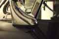 By this time I'd refitted the reinforcing-plate behind the skin with just the screws going through the plinth, discovering in the process that I'm probably not as flexible as I was 30 years ago! At that point I was more concerned with whether I would be able to fit it or not, forgetting that I'll have to remove the screws to fit the new wedge. But maybe by removing one screw and fitting the wedge with that with the screw going back into the plate, I can use that to support the plate while I remove the other screw, swing the block round, and refit the second screw. In the event it was easier than I thought - the first screw through the new wedge just nipped up, with the wedge at an angle to clear the second screw. Remove second screw, then with a screwdriver back in the first screw preventing it from turning, and maybe turning the reinforcing plate with it, swung the wedge into the correct position and fit the second screw. When fitting the mirror after tightening the screw I slowly slackened it again while trying to lift up that end of the mirror from the plinth. You are looking to see if the mirror slowly lifts up as the screw is turned, but if it pops loose as soon as the screw starts turning it's not fully locked in place.
Mk1 or Mk2? June 2020
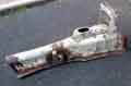 Lots of detail differences, several of those being fittings which could have been changed, but the most obvious to see and the least likely to be changed is the tunnel. The Mk1 has a pronounced hump round the gear lever, whereas the Mk2 and later is flat. You can't go by what gearbox you have i.e. 3-synch or 4-synch as it's not that uncommon for a Mk1 shell to have been fitted with a 4-synch gearbox, in which case the large removable panel on top of the tunnel has to be extended to move the gear lever hole back.
Mud-flaps September 2017
After body paint and engine rebuild over 2016/17 I debated whether to refit them. Vee is used more as a daily driver than Bee, so even though I have never fitted them to Bee I decided to refit them. Vee being a rubber-bumper GT they don't look as 'heavy' as they would on chrome-bumper wire-wheeled roadster. Even though one pair of the original flaps was sound, they were very shabby, so I opted for two sets. This time with a monochrome MG octagon in white on black rather than the red and white of the originals. There are also MGB and particularly V8 variants, but I didn't fancy those.
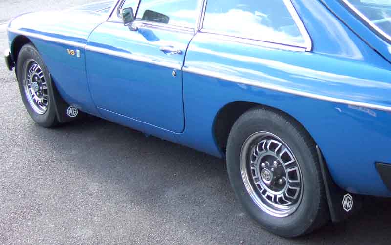 Fitted with a choice of clamps or massive screws and washers which would mean drilling through the arch flanges, I opted for the clamps, but found only moderate resistance when tightening the screw, until the head 'bottomed' on the face of the clamp. Fitting to a curved face, there is a wide range of positioning available, but anything other than the outer vertical edge being truly vertical looks odd, to say the least, so a carpenters spirit level sliding on a metal ruler was used to judge that. A bit of a fiddle holding the flap in the right place, and the clamp going round the flange and the flap, and tightening the screw first on one then the other, and that only enough to hold the flap on while one applies the spirit-level, and slides the flap round the curve one way or the other to get it vertical.
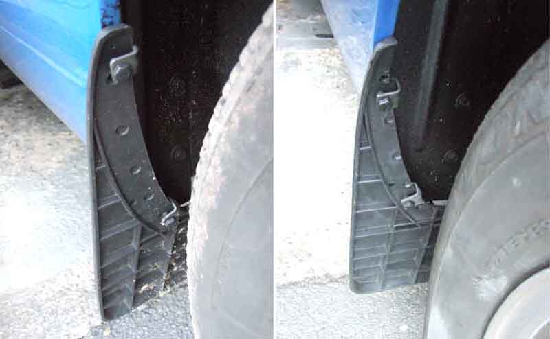 Fitted, they stick out a bit and look quite clunky, as the flange on the flap is a good inch whereas that on the wings is about half that. So off they come with a view to trimming off a centimetre or so. But I thought I'd practice on one of the old ones first - to find they have a metal insert in the curved section that goes against the wing flange, which means that the screws can only cut into a relatively thin bit of rubber before they encounter the metal, and pressure from further tightening of the screw clamps the remaining rubber firmly between two sheets of metal - the insert and the wing flange. The new ones have no metal insert, so the screws in the clamps cut into the rubber until the head 'bottoms' against the clamp. One wonders how long it will take for the rubber to extrude out from under the screw, clamping force being reduced, and for a flap to fall off!
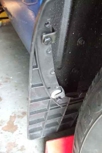 Hunting through my several containers of miscellaneous bits and pieces I find a number of thick 'washers' with a tab on one edge, and a small hole in the middle. Had them so long I can't recall where they came from. I find five, so four of them will be enough for one per flap, which should be more than enough to keep hold of them. Cut the tabs off, and fit them under the screws in the lower clamps.
Number Plates September 2019
September 2021: For foreign travel from 27th September 2021 (except to Ireland) you will need to display a UK sticker clearly on the rear of your vehicle if your number plate has any of the following:
- a GB identifier with the Union flag (also known as the Union Jack)
- a Euro symbol
- a national flag of England, Scotland or Wales
- numbers and letters only - no flag or identifier
If your number plate includes the UK identifier with the Union flag (also known as the Union Jack), you do not need a UK sticker.
If you're in Spain, Cyprus or Malta, you must display a UK sticker no matter what is on your number plate.
If you have a GB sticker, cover or remove it. (This last is a bit of a beggar as both Bee and Vee have stainless 'GB' badges with holes drilled for the mounting studs. I doubt 'UK' would use the same fixing holes ... even if I could find any!) More fall-out from Brexit. The letters 'GB' have historically been used in many areas of life and technically that excludes Northern Ireland. The EU were using that to say the UK should have different rules for Northern Ireland compared to mainland Britain, hence the UK Government replacing 'GB' with 'UK' in their argument that we are a single entity.
February 2021: Having said that Roger Parker writes in this month's Enjoying MG that there have been some changes partly as a result of Brexit: From 1st January 2021 vehicles built after 1st January 1980 will not be able to display black and white/silver/grey plates when they eventually become eligible for the Historic class. Whilst legislation dated 2015 states that only vehicles registered in the Historic class will be able to show black and white plates, the MOT Manual only states that cars first registered prior to 1st January 1980 can show them, it doesn't mention that they have to be in the Historic class. Also plates purchased from 1st September 2021 will not be able to show the 'Euro' stars or national flags, although existing plates can continue to be displayed while they are still legible and undamaged. For foreign travel (Ha!) a GB oval (but see above) must be displayed with the new plates. Also outlawed will be '3D' or two-tone digits, only solid black will be allowed. Mind you, fancy fonts were outlawed years ago but they haven't been 'driven off the road' yet. It's not completely clear (ho ho) whether 'lipped' plates are still allowed or not, for insertion of a legend of your choice. The British Number Plate Manufacturers Association site contains info on the new standard but does not mention that feature. It is covered elsewhere on the site but under the previous standard BS AU 145d so I suspected that is something else which has gone by the board. However I enquired of the British Numberplate Manufacturers Association and secretary Stephen Beasley wrote back "The Association is not aware of any changes to lipped plates as a result of 145e".
 Vee's rear plate had delaminated quite badly when she came to me, dirt had got in between the clear acrylic face and the adhesive backing with the characters making the number partly illegible, and it was picked up on an MOT. I had a new one made, which was constructed the same, and that started delaminating as well. After painting Vee in 2017 I pondered replacing it again, but decided not to until I was forced to as the same construction was quite likely to go the same way. However it just did not look right given the quality of the finish everywhere else, so I took the plunge. Trotted along to Halfords with my documents, and I noticed a completely different construction method. Whereas before a grid over coloured film was used to space and position the letters correctly and individual letters picked out of pigeon-holes and placed in the grid. Then a clear acrylic plate was laid over the letters and a roller run back and fore to stick the two together. Now, and inevitably, it's done on a computer! The registration is entered using a keyboard and screen, a button pushed and a laser or thermal printer produces a strip with the characters on coloured reflective film, or on clear film, depending on the specific process. With the coloured film a clear acrylic plate is put adhesive side down on top of the film and the two rollered together. With the clear film a coloured reflective backing plate is used, adhesive exposed, the film placed on top and rollered. Halfords seem to use the latter process as the backing plate looks to be alloy (Metatek?) with the numbers right on the outer surface, rather than behind clear acrylic as before. Hopefully delamination will not occur as it's one of the tests the new plates (to BSAU145d) have to pass.
 The character spacing is obviously different to how it was before - so care is needed when fitting your new plates. With the previous new number-plate and backing-plate I opted to put the screws through the yellow part rather than the characters, drilled the backing-plate to suit, and used yellow fixings. Keeping the backing-plate (repainted as part of the restoration) I used the old number-plate as a template to drill holes in the new number-plate ... to discover the holes were in the characters! Easily dealt with, I just painted the yellow fixings satin black before using them, but it would have been really annoying to have drilled through the edge of a character! Had I spotted it before drilling I might have opted to drill two new holes in the backing to stay in the yellow, but I prefer this way. If the screws start peeling and showing yellow I can always splash-out on a couple of black ones.
Passenger Foot Brace (aka 'Numpty Board')
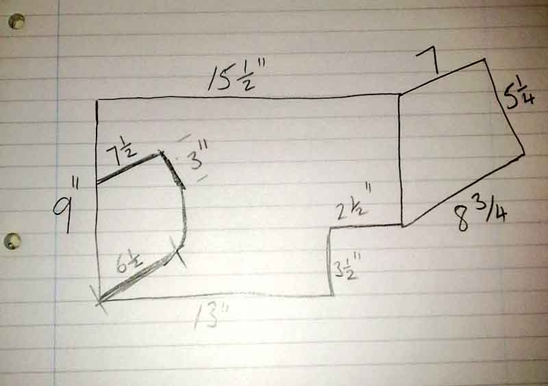 Michael emailed a sketch to me as a starting point, and I fabricated a trial unit using hardboard for the sides and an angled piece of wood for the foot-rest. The shape of the MGB footwell is quite convenient in that the side pieces can be shaped to 'dig in to' the angle between floor, sill/tunnel and toe-board so it doesn't need to be bolted in and can be removed in a moment for vacuuming or transferring between cars. As leg length varies from person to person, the seat adjuster gives quite large steps, and I like to keep the two seats in line (OK, I know it's a bit James May, and I do like to keep the dashboard fresh-air vents straight and level when closed but at least I don't carry a toothbrush to clean the slots ...) we got the basic fore and aft position of the board by her sitting in the seat and holding her feet at a comfortable position, and I stuck masking tape on the sill and tunnel carpet to give me a measuring point for the length of the side pieces. I then used card trimmed bit by bit to get the basic shape as there are several angle changes of the bottom of the side pieces from front to back, and finally transferred that shape to hardboard. Now I know hardboard isn't very strong and heavy braking (from me or the Navigator ...) is likely to break it, but this was just a trial to get the right positioning before constructing something more robust.
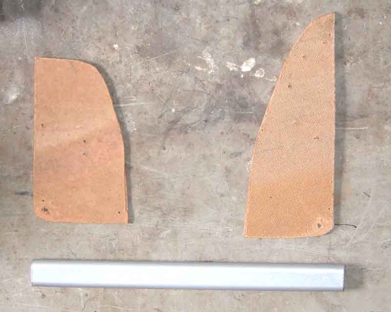 However whilst the Navigator found it useful she does like to move her legs and feet around which the angled wood didn't really allow for as it kept her knees and ankles at the same angle all the time, so the MkII test unit was born. This has a length of wardrobe rail as the foot rest between the side-pieces, which allowed her to rest either her soles, instep or heels against the bar, or indeed have her legs at full-stretch and the backs of her heels on top of the bar, all of which allowed her to change the angle of ankles, knees and hips as and when. As the foot-well narrows on the tunnel side as you move forwards, and the bar is the full width between the sill and tunnel, the tunnel side piece angles in slightly, hence the end of the bar that side is angled to suit. The wardrobe rail used for the bar is hollow tubing so I cut wooden inserts to slot inside for about an inch, then a screw through the side pieces into the end of the inserts expanded them to wedge tightly into the ends of the tube. That is, until the wood dried out and shrank a bit, but it's still tight enough to hold the bar firmly.
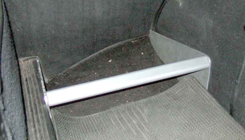 After a couple of weeks of long and short journeys she pronounced herself satisfied, so the shape of the side-pieces was transferred to offcuts of 3/16" aluminium sheet I happened to have, and the gold-coloured bar painted flat silver to match. Oddly, when installed this put the bar at a bit of angle, with the left-hand deeper into the footwell than the right-hand than the test unit seemed to be, so I had to extend the left-hand piece by about half an inch by MIG-welding a bit to it. Subsequently I made a second one for the V8.
Sill Quarter-panel Replacement
This is because they cover the end sections of the sill panel, which runs from the back of the front wheel arch to the front of the rear wheel arch, and there is only a gap of about 1/8" or so between the two panels. The narrowness of this gap means that even if they are treated with Waxoyl by spraying from above (by removing the splash panel in the front arch and the trim panel behind the doors) it will almost certainly just form a bridge across the top of the gap and not penetrate it. So even if the sill itself has been painted after fitting the back of the cover panel cannot be, and with the oxidation caused by arc or MIG welding corrosion starts eating away at the new panel almost immediately. Closing the gap quite possibly accelerates this process as it will prevent circulation of air, so any moisture that gets into the cavity from below e.g. as a result of road spray cannot dry out easily.
Eventually the corrosion will become visible on the outside of the cover panel as bubbles with rust streaks running down. This usually happens near the bottom of the cover panel where it curves round underneath, which makes it easy to miss and even easier to ignore for a while, until it gets bad enough to be worth doing something about.
Once the cover panel starts to corrode inside the cavity it actually becomes thicker - the products of corrosion having a greater volume than the original metal - and this gradually fills up the gap between the cover panel and the sill. Flakes from further up also fall into the bottom of the gap, eventually bridging it, and the rust debris comes into contact with the sill panel. The debris gets wet from the aforementioned road spray and takes a very long time to dry out - possibly never in a daily driver in anything other than a desert environment - and this starts rotting the sill panel too. If you leave replacement of the cover panels for too long, when you finally 'get a round tuit' you may find considerable corrosion or possibly even holes in the sill too even though the sill may have been protected by spraying the inside of the box sections.
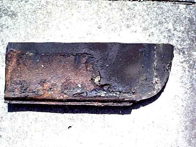
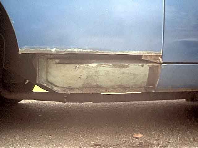 In the first of the pictures here you can see that the lower part of the cover panel that was adjacent to the sill is heavily corroded bare metal, whereas the area immediately above and in front of the sill is completely covered with a waxy protective coating and has no rust at all. Although I left replacement perhaps longer than I should have, the sills were almost completely rust free with just one or two very small patches of surface corrosion, otherwise being painted a curious metallic silver-green as can be seen in the second picture. I was lucky.
 There are some special fittings used in wing fitting, as shown here.
I don't intend to go through the full description of replacing body panels, just a few points specifically concerning these two. I chose to cut the existing panels just above the top of the sill in an area that was rust-free, in order to keep the repaired area to a minimum. If replacing the sills at the same time you will probably have to cut higher for access. I used a nibbler in a drill and flanged the repair panel to fit behind the bottom of the existing panel to keep distortion of that panel to a minimum - that is your datum. The rear panel is easier to deal with as it is welded to the rest of the car on all bar one of its edges and this should give you the correct fitting relatively easily. The exception is the leading edge that curves round the sill. This should have a right-angle flange to it but on all of mine it was too deep and even though it fits into a recess on the sill panel it was still proud. Rather than grinding it down I choose to fold it further onto the back of the panel, carefully so as not to distort it, trial fitting it until a straight edge runs cleanly across the sill and the repair panel with no gaps. Test the coating on the repair panels with cellulose thinners. If it comes off easily then it is just a shipping coating and must be removed before welding in place. If not it is a primer that can be left, although the edges that are to be welded should be cleaned back to bare metal. In both cases coat the whole of the back of the repair panels with a zinc-rich weld-through primer before fitting. After welding, the curved join between the sill and the repair panel should be treated with seam-sealer, but do not flush it over, leave a shallow vertical groove.
With the front panel the front edge is unsupported so you have to be careful to get the correct curvature. As you want to keep a gap between the sill and repair panel I placed a strip of wood about 1/8" thick along the top edge of the vertical face of the sill for the repair panel to butt up to. Screwing along the bottom edge and welding along the top edge, then removing the wooden strip, leaves this gap. Without the temporary wood packing you could end up with no gap between the sill and repair panel which will cause problems later. But before welding careful work with angle-grinder, hacksaw and files is needed to get a good join where the horizontal welded joint meets the vertical door opening. The join between the rear edge of the repair panel and the curved part of the sill is not treated with seam-sealer but left open.
After welding, shaping, and painting we want to limit the possibility of corrosion occurring again, if no action is taken the welded edges will start rusting almost immediately. Unless you are in a very hot climate and the body panels are equally hot a product like Waxoyl, although you may be standing it in a bowl of hot water to liquidise it, will return to its normal 'tacky' state immediately when sprayed and not run down the 1/8" gaps between sill and cover panel but simply lie along the top of the gap. Either thin the Waxoyl with white spirit to a liquid and spray it in a jet rather than a fan until it runs out of the bottom of the sills (onto newspaper for example) or spray clean engine oil into the gap which will similarly run out. Get a strip of card (not metal which will scratch) and poke it into the gap to ensure the Waxoyl/oil is fully distributed along the length and height of the gap, then spray some more in. With Waxoyl you may find that it drips again in hot weather, whereas with oil it shouldn't. Don't be tempted to put the Waxoyl that has dripped out back into the pressure can for reuse, it may contain particles that will block the jet sprayer, but you can use it for brushing on behind the front arch anti-splash panel and elsewhere. Dinitrol is often mentioned as a superior product to Waxoyl, and it is true it runs much better as it is thinner, but by the same token it is more likely to run straight down the narrow gap and not spread sideways. I still prefer Waxoyl for this area, but the long cavity nozzle that is available for Dinitrol is far superior to the 'nail in a tube' of Waxoyl for other cavities, and Dinitrol comes in aerosol cans so is far easier to work with than the Waxoyl pump system, never mind standing it in hot water or waiting for a hot day. Once spraying though, Waxoyl does go on thicker, Dinitrol runs everywhere including out of the tiniest hole, although that does show it is getting into the tiniest cavities.
Don't be tempted to seal the bottom edge of either front or rear repair panel with seam-sealer or equivalent. You must allow any water or moisture to run out and not gather, and you will notice that the sills and castle rails have drain holes (see 'Sill Construction and Drainage' below) for the same reason. It is better to protect the cavities and allow some water from road spray to get in then drain freely out, than to try to prevent any getting in and end up trapping it which will accelerate corrosion.
Note: Even if your 1/4 panels do not need replacement I strongly recommend you make sure the top of the gap is clear then squirt a jet of clean engine oil into the gaps and distribute it with a strip of card. Do this even if the panels above the gap show signs of treatment to ensure it has got right to the bottom of the gap. Although Vee had been comprehensively treated these areas had been missed (although I squirted oil in them some years ago), and they aren't even mentioned in Lyndsay Porters Guide, a significant omission in an otherwise excellent reference book.
Folding the hood/top
Front bow fouls the body
Header rail seal
Replacing the hood/top
Hood/top fittings
Interchangeability of tops and frames
Frame mounts
Decals
Originally as standard the MGB had a pack-away hood that was completely removed from the car and the frame dismantled into two parts, as well as an optional folding frame. The pack-away frame slotted into two sockets screwed to the inner panel aft of the doors, and the folding frame screwed to the same welded nuts on the back of this panel. In 1970 both of those were replaced by an improved folding frame, and the bulk of his section describes that.
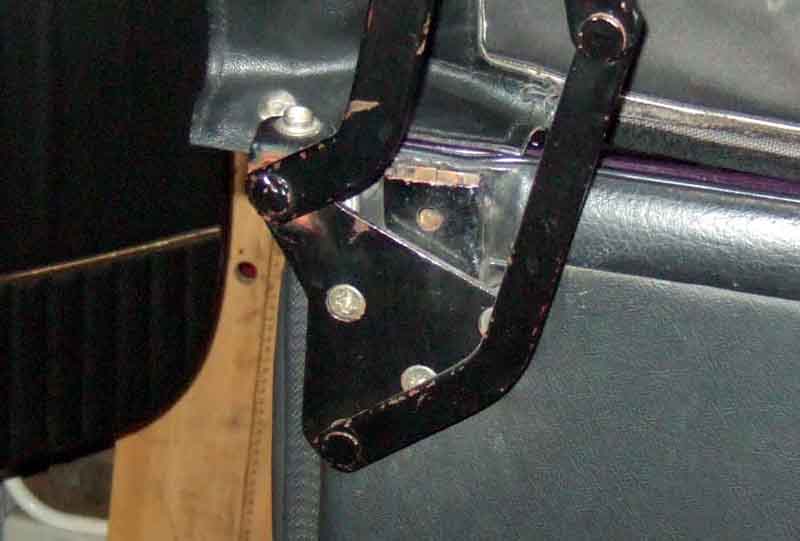 The pack-away frame sockets can be installed with either of the folding frames to be used for the tonneau or hood cover sticks, the sockets are also used for the hardtop.
Octagonal Origami (or, the art of folding the MGB hood)
Hood straps
Front bow fouls the body
My hood/top doesn't fold low enough
I posted the following on the MG BBS in response to an enquiry, and one person was kind enough to contact me and say it had helped him, so I decided to include it here. It relates to the 1970-on Michelotti hood, not the packaway or earlier folding types for which see here.
By the way I keep seeing exhortations not to fold the hood if it is damp. Fair enough, I wouldn't put the car away with a damp folded hood, but are you going to keep driving with the hood up after a shower now the sun is shining again? Nor am I, but it does go up again when I get to my destination. In fact I always erect the hood when in the garage, just in case the roof decides to start leaking.
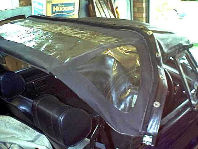 With all fasteners (front and rear) undone I pull the header rail back just enough for the hood to clear the slotted chrome teardrops (officially 'plate-retaining hood-rear') behind the cockpit, then push the header rail forward again. At this time the rear window is dangling down behind the rear seats,
I lift it up and forward and lay it over the central part of the hood.
With all fasteners (front and rear) undone I pull the header rail back just enough for the hood to clear the slotted chrome teardrops (officially 'plate-retaining hood-rear') behind the cockpit, then push the header rail forward again. At this time the rear window is dangling down behind the rear seats,
I lift it up and forward and lay it over the central part of the hood.
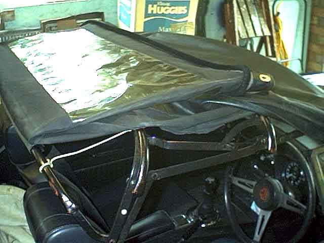 The quarter-lights are now sticking out at the sides. I lift the rear window part and tuck each rear quarter-light under the rear window so that they lie between the rear window and the main part of the hood. If you get this right the three pieces of clear plastic (rear window and two quarter-lights) will be lying flat, unfolded, uncreased and all the folds will be in the black vinyl. You can see one of the cords that pulls the rear bar into the correct position when the hood is erected.
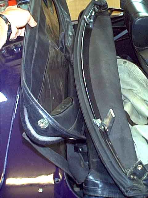 I now pull the header rail back lift the rear bow by pulling up on the trailing edge of the vinyl (the part that hooks into the chrome thingies behind the cockpit) so that the rear bow doesn't wedge on top of the inner arches, and lower the whole thing down into the space in front of the rear cockpit rail.
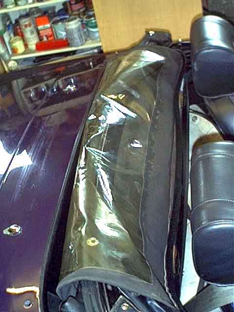 Finally I drape the rear window part, complete with tucked-in quarter-lights, forward over the header rail, making sure the header rail clamps are closed. If you fold the black vinyl edges correctly it is these that lie over the screen fasteners and not the clear plastic.
I have seen two pieces of cloth employed at this point - one between the clear plastic and the header rail and the other between the tonneau cover and the hood to protect the clear plastic but personally have not bothered to do this - after nine years and 25k wet and dry miles my windows are still in pretty good condition.
With the rear bow attached to the hood material using the two strips that are provided for this purpose I found the bow wasn't in quite the right place when the hood was erected, but too far to the rear. I now have two cords, one each side, tied between the middle and rear bows, and adjusted so that the rear bow is pulled up right under the seam as the header rail is pulled forward. See the 2nd picture above. Subsequently I discovered the early folding frame had something similar as standard. It was two lengths of webbing joining the front and rear bows and going over the middle bow. One can be seen clearly in Clausager on page 54, 2nd picture down, as cream webbing contrasting with the black hood material and grey frame. Also a glimpse of it in the bottom-left picture, which also seems to show the rear bar sewn or glued into hood material flaps the same as the later hood.
Hood straps: November 2020
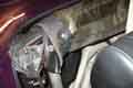 You should have two hood straps (or rather two ends of one strap each side) that allow the rear part of the hood to be rolled round the bottom part of the whole folded arrangement and held up out of the way of anything on the shelf, but although I have these straps I use the full-length tonneau cover as a hood cover fastened to the rear heel board so there is no need. Some people seem to really struggle with these saying they are difficult to find and fasten, and unless they are used the hanging hood interferes with the inertia reels. None of which is a problem for me, but I can understand that with a mohair or lined hood the additional thickness may well mean that the original strap press-studs may not meet, or pop-apart. Some say they have provided longer, loose straps, but they get lost. I really can't see what is so difficult in replacing the originals, or extending them, and using Velcro so press-stud positioning isn't critical.
Front bow fouls body: April 2015
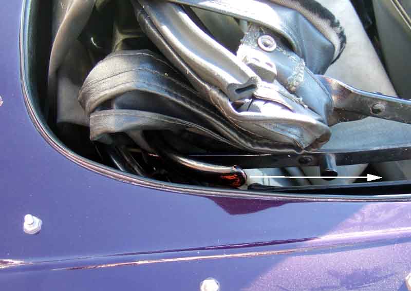 I've been folding Bee's hood for 25 years without a problem then suddenly one time last year the ends of the front bow were fouling the body both sides. It took me a few minutes to realise that for some reason this bow had pivoted, and stuck in a different position to normal. Normally when erected the ends of this bow point downwards, and when folded they should point straight forwards and tuck inside the cockpit rail with a clearance. If for any reason they are pointing too far backwards when the hood is erected, they will be pointing straight down when the hood is folded and foul on the cockpit rail. Since then it started happening more often, and now (September 2015) happens every time.
September 2015:
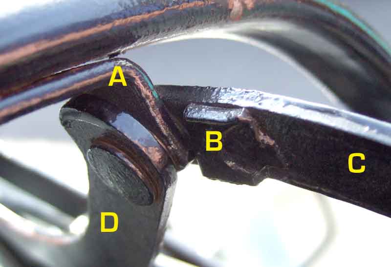 Looking at where the front bow pivots there is a block of metal welded beside it, which looks as if it was an afterthought to stop the bow pivoting at all, or only very slightly at most. But after 42 years wear has taken place in various places so that the block no longer restricts the movement of the bow. It seems that the sides of the bow support should butt up against the edge of the block, which would put the bow almost vertical. But in that position, when folded the ends of the bow stick up which isn't ideal for the hood cover or tonneau cover. With the ends of the bow pointing straight forwards when folded, they are pretty-much the same angle to the vertical as the middle bow when erected. However at that angle, because of the wear in the bow support and the block, the corners of the bow support are overlapping the block which can't be right. Looking at two pictures in Clausager the front bow does seem to be almost vertical when raised, which would put the side of the bow supports against the edge of the block. The bow support is sandwiched between two other parts of the hood frame - a short curved piece pointing backwards to the outside, and a longer curved piece facing forwards to the inside, but it only pivots in relation to this longer piece while being folded. It doesn't need to move in relation to the shorter outer one at all, so could in theory be welded to it. But I shall ponder for a bit whether to do that, or weld another block on top of the existing one, ... or ... something else.
February 2018:
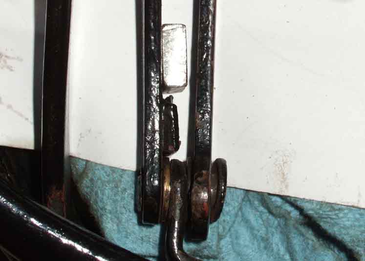 With Bee Hors de Combat while the head is converted to unleaded I decide to tackle the hood frame. After some examination off the car and pondering I'm minded to grind off the existing blocks, weld in a thicker one, and closer to the bow bracket, to overcome the wear in the pivot.
My hood/top doesn't fold low enough July 2008 This relates to something that happened when I restored the car some 19 years ago, so I don't have any photos and it is dependant upon memory to a large extent. I'm only including it now as someone has written to me with what seems to be the same problem, although it doesn't appear to be a common one as I can't recall anyone coming back when I mentioned it on the various lists and BBs some years ago.
When I first had the roadster it came with a full-length tonneau cover with snaps half-way along so it could be used as a hood cover as well, the front half of the cover being tucked up under the folded top on the shelf. However my hood sat so high when folded that the snaps were nowhere near the posts on the heelboard, whereas pictures of cars showed the top of the hood dropped right down into the space behind the seats. But what I could do was fold the hood back with all the rear fasteners still done up, which made it very quick and easy to erect. A friends car of the same age (73) was exactly the same, and he related how he could erect his top while driving along!
 When I restored the car I wanted to get the hood lower so I could use the tonneau cover as it does look much neater, and after some pondering realised that a couple of the struts in the frame were folding as far as they could, then jamming, and that was stopping the top and frame folding all the way down. After a bit of beating on these struts (time elapsed prevents me from remembering which) and changing the angles 'lo and behold' the frame and cover now drops all the way down as shown here, with the frame bows resting on top of the inner arches, and I can fasten the tonneau cover heel-board snaps and now have a neat hood cover. But I then discovered I can no longer fold the top back with all the rear fasteners in place as it traps and stretches the material. No matter, I'd rather have the neat folded appearance.
May 2020:
 Martin White asked about this on the MGOC forum even though his looked much lower than I remember Bee's being before I made the 'adjustment'. I described what to look for (a strut trying to push its pivot pin past the pivot where the frame didn't collapse any more, instead or rotating around it), and he reports back that having taken his frame off the car and put it on the ground as I did, he found the strut that was causing the problem, and adjusting both sides now allows the frame to drop down completely. He also writes that on his other roadster (which drops right down) this strut does appear to have been bent, he says by a previous owner, but given the variability between cars I'm wondering whether it is just manufacturing tolerances. Also looking at the piece in question, and his 'before' and my 'after' pictures, I'm wondering whether we made the same adjustment. But no matter, we are both happy now, and it may help others.
I've got the sticks, but it is a real stretch to fasten the snaps of the full-length cover when used as a hood cover, and it doesn't really make that much difference to the appearance anyway so I don't use them. I think they are mainly intended in that position to shape the separate hood cover which I don't have. Where the tonneau sticks are useful with the full-length cover is when both sides are fastened full-length, when if you position the sticks in front of the seats instead of behind it lifts up the centre of the cover so rain runs off the sides instead of pooling in the middle and dripping through the zip. I've never seen this advice anywhere else.
I don't understand why so few stick up in the air like mine did, unless it was a different manufacturer of the frames for a while, but even then I'd expect more cars to be affected. Having said that at the Stafford MG Enthusiasts run to Upton House in September 2009 I noticed quite a few of each type i.e. some low and some high. These were all the later Michelotti style, and there didn't seem to be any correlation with the year i.e. some early and some late with both appearances. No pics, maybe next year if I remember.
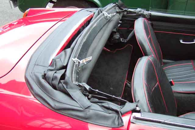 This 65 roadster has the (later Michelotti) frame dropped pretty-well all the way down, but also has the rear still fastened to the rear panel! However it is a later zip-out hood, maybe that makes the difference.
 I've seen complaints that the inertia reels prevent the hood from folding all the way down, but if they are fitted correctly that can't happen.
Header rail seal
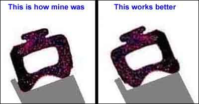 When closing the hood I'd always had to run a finger along the seal in the gap between the header rail and the screen top rail from inside the cabin to prevent the rubber seal getting trapped by the flange on the screen top rail, which was a pain. When I received the new seal I immediately noticed that it was slightly asymmetric front to rear in that the two 'bumps' on the seal that press down onto the screen top-rail are slightly off-set. I checked the old seal and found that this off-set was rearwards (i.e. to the left in this profile image) which could account for the seal getting trapped. Fitted the other way round the rear bump drops neatly onto the screen top rail without getting trapped. But the forward bump, instead of lying flat on top of the rail, now lies on the angle between the top and front faces. My first thought was that this can't be right, surely lying flat on the frame rail is correct, but then it occurred to me that being on an edge rather than a flat surface it probably conforms to the shape better giving a more effective seal. Since then it has never leaked even in torrential rain, whereas it had before. Someone subsequently stated that the bumps should be rearward as the original was, and they hadn't had problems of the seal getting trapped. The new seal may have been responsible by itself for the non-leaking now i.e. whichever way round it was fitted, but as it doesn't leak, and as I don't get the trapping problem either, it will stay as it is.
October 2004: Torrential rain and a howling gale on the way back from the MGOC Autumn Gold run (ditto while on the Lincolnshire Wander in 2005). Absolutely nothing came past the header rail seal.
October 2018: A certain eBay supplier is listing this seal using an image that looks like it has been filched from Motaclan/Leacy. Someone on the MGOC forum purchased one from eBay and found it significantly different in profile to the one pictured. Not only that but the eBay one was �8.35 whereas Motaclan/Leacy's is �4.26. Yes the eBay one is post-free and P&P is extra from Motaclan/Leacy, but if buying with other parts the P&P on that item will be marginal at worst.
Two things to be aware of here - buying a new hood, and fitting it.
I will deal with the fitting first as it may impact on which one you buy. IMHO you must read through a set of hood fitting instructions, such as those contained in Lyndsay Porter's excellent "Guide to Purchase and DIY Restoration of the MGB" before embarking on the task. It may incline you towards buying a hood without header rail already fitted or indeed the other way. Personally, I feel that buying without may well result in a better fit, albeit at the expense of extra effort. Buying one with header rail ready-fitted is a lot simpler but the resultant fit may not be as good if your screen/hood frame/rear fastening dimensions are not exactly the same as the template used by the manufacturer of the ready-fitted item. You don't want something that is going to look like Nora Batty's stockings (see Last of the Summer Wine).
Buying
The hood on my roadster was replaced shortly before I bought the car and is probably one of the cheapest you can get - single thickness vinyl. Although it is waterproof in itself its fit to the remainder of the car is less than perfect in one or two places so I have been considering replacing it with something of higher quality.
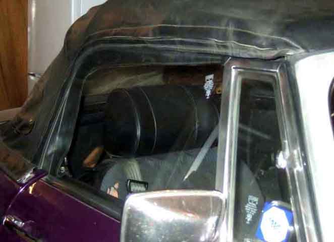 In May 1999 we stayed at a hotel in Guernsey for a few nights with a group of other MG owners from across the UK so the cars were in the hotel car park overnight with the hoods erected. I was amazed to see the variation in fit amongst the cars, and even more amazed to find that mine was one of the best. On my hood the gutter rail just reaches the top of the side windows and there is a flap of vinyl that hangs down inside the glass for an inch or so. On some of the better quality and more expensive hoods this flap barely reached the top of the glass and the gutter was way above it. Furthermore the flap was bowed in leaving a considerable gap between it and glass, which meant that with the slightest breeze any rain would blow straight into the car. Others I have seen have a much deeper flap inside the car, which although it seals just fine, is probably in the way when looking to the side. At least you could trim that back. This Prestige hood seems to combine both with the gutter a good inch above the drop-glass as well as a deep internal flap, but at least it lies flat. So, when considering buying a new hood, carefully measure from the top of one side glass, over the middle hood bow and down to the top of the other side glass, and compare with the gutter-to-gutter measurement of the new hood. Hold out for a good fit, new hoods are not cheap and you are likely to be stuck with it for some time.
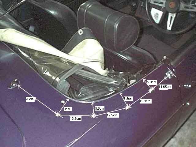 I've been asked a couple of times now for a diagram and dimensions of the hood fittings, so here it is. The hole to the left of the 8cm line for the rear-most peg is the tapped hole for the static shoulder belt attached with a quick-release fastener for some markets in various years. The front-most peg is measured from the front of the socket for the hood/top tongue, and has a press stud close behind it, which is for the tonneau cover.
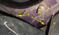
 And how to get at the nuts that secure them.
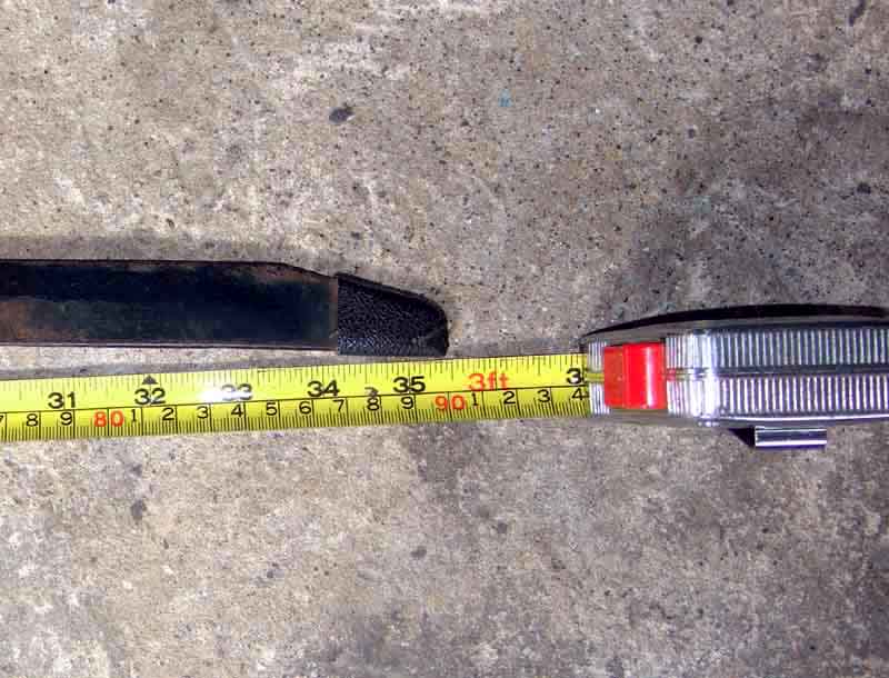 Another question popped up on the length of the retaining bar at the back of the hood. I knew it had chamfered ends to follow the curve of the hood material, and little boots on the end to stop it wearing through, but I hadn't realised the whole bar was curved, even though the pocket itself seems to be straight.
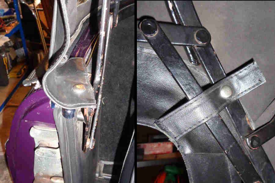 For the three press-studs each side round the drop-glass positioning of the females in the hood material is best done on the car using the position of the males on the hood-frame as a guide, rather than giving measurements.
Interchangeability of tops and frames February 2018
There are occasional questions from people wishing to upgrade their hood and asking if it's possible. I can understand people wishing to upgrade from the packaway hood as that takes a while to sort out in a sudden shower, and apparently when the early folding ('scissors') hood is detached from the screen it flops all over the place instead of being self-supporting like the later Michelotti hood, so not quite as easy to raise and lower especially if one's Navigator is sitting in the passenger seat at the time. It's almost certainly true that any frame type will fit any body, as all use the same fixing points at the top of the B-pillars either indirectly using the tonneau sockets for the removable hood or directly for the two folding hoods. The pack-away sockets can also be fitted with the folding frames so tonneau cover bars can be used. But it's after that it gets a bit complicated.
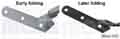 For the early hoods the header rail was the same for both - BHH496 - probably because the header rail has no attachments to the packaway frame, unlike the two folding frames. However the top including header rail is different between the two - AHH8516 for the packaway and AKE5372 for the scissors indicating the tops themselves are not the same. The rear fastenings should be the same as the early folding was an optional extra, so it probably means the fit is different over the two frames. Both the later folding hood complete with header rail, and the header rail itself are different part numbers again - BHH905 for the cover with header rail and AHH6437 for the header rail itself, however several of the main suppliers list the earlier header rail for all models, implying that the rails themselves are ostensibly the same and it is the tops that are again different. As far as rear fastenings go Kelvin Dodd of Moss US writes:
"In reality, the rear snaps moved around quite a lot when the V8/rubber bumper shell was built. I've done some research on this and have found that the stud location on the cars up to 1974.5 is pretty standard. From then on the snaps vary even from side to side. To allow the later tops to fit these later cars accurately the snaps and even the cut of the top from some manufacturers is slightly different.
"The changes in the rear lift a dot fasteners correspond to the re-shell, not to the introduction of the fold back frame design, but there may be slight differences in the later examples of this frame.
"Thankfully this is not enough to make it impossible to fit the earlier cars as the differences are in the order of a few millimeters, but it does require some stretching to fit all the rear snaps.
"The other thing that is interesting is that installing early stow away bows and top on a post 1975 car results in the rear seam not being in line with the rear bow as would be original for the early cars. So far my best guess for this is that the location of the tonneau bar mounts is slightly off on these later shells. Again, there is no reason for this, other than the looser tolerances in the shell fitment."
'Steve' asked this question on the MGOC forum as he was proposing to substitute a folding frame for his pack-away, and wondered which type of frame to get, and whether he would need a new top. I went through the above, he 'plumped' for the early folding frame, and his pack-away top and header rail fits just fine.
Frame mounts February 2018
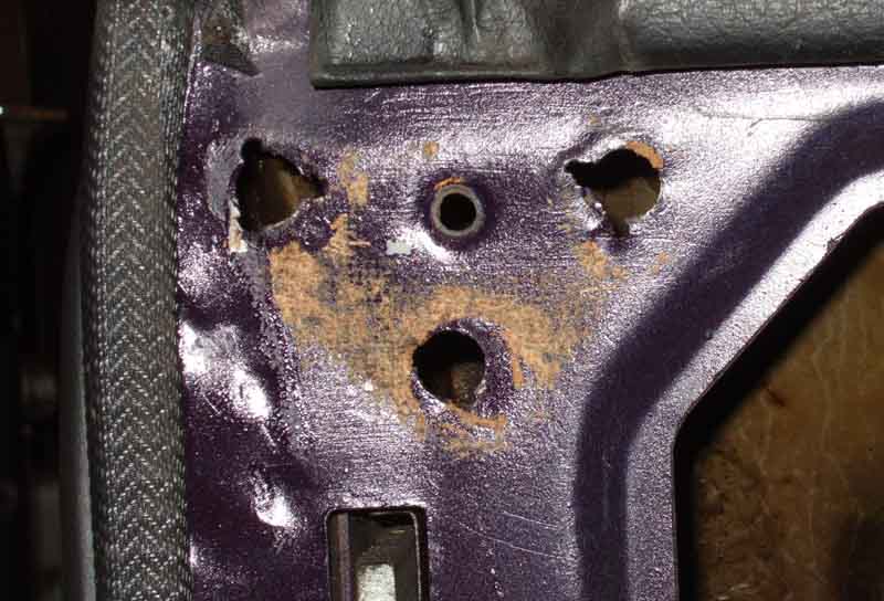 There are three nuts welded to the inside of the rear inner wing, just behind and at the top of each B-post. This panel isn't particularly strong, so can flex as the hood is raised and lowered, and the nuts can tear free. Also using standard nuts there isn't much engagement with the three screws, and the threads can strip. Oddly, the screws are way too long, with about an inch or more protruding from the nuts. Bee came to me with both these problems and the hood frame flopping about all over the place, tearing the trim panel.
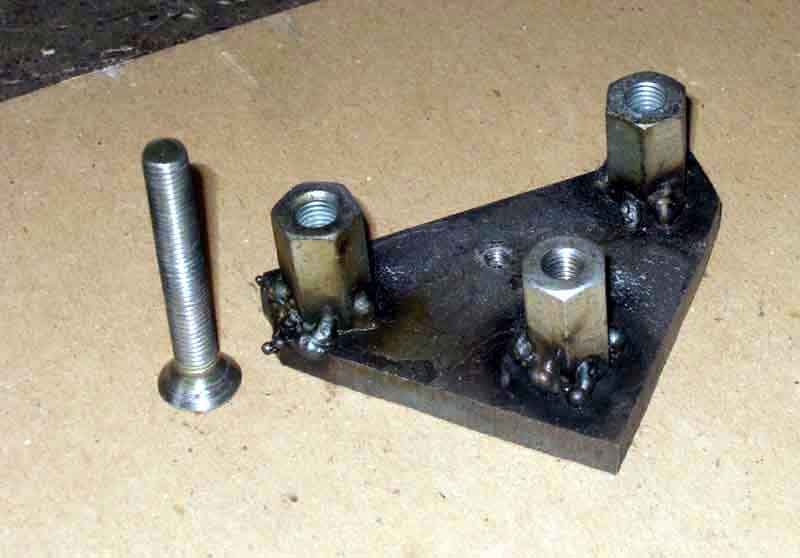 When stripping Bee for a repaint I had noticed that the nuts under the quarter-light are about three times longer than standard nuts, and given the very long screws would be an ideal match. But how to fix the nuts? Welding them to the panel would just pull out again, so I decided to weld them to a thick triangular plate, which would be held to the panel with a single screw. It's true that whilst you are fitting the three screws the triangular plate can move about a bit, but if you support the frame in the correct position while tightening the screws, once tightened - and given the thread engagement is now three times what it was before, you can get more torque on them without stripping and they are never going to move. And over the past 30 years that has proved to be the case.
June 2018:
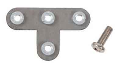 Moss US have produced a similar thing albeit with much less substantial nuts, and a larger pan-head screw instead of the countersunk I used, for which a hole has to be cut in the trim panel. Not listed on the appropriate Moss Europe 'Hood Frame & Tonneau Cover Fittings' page, but can be found by searching for the Moss US part number 472-328. Someone asked me whether the existing nuts should be removed. On the face of it yes as with the plate flush to the back of the panel and the screws tight that would resist twisting as the hood is raised and lowered better than if the plate were sitting on the old nuts. However if the nuts are present but the threads are damaged drilling a clearance hole through them will allow them to act as a locator, and the frame would not twist back and fore while tightening the screws. Of course if some are missing then short of replacing them with some other spacer that will allow the plate to be installed parallel to the panel, you will have to fully remove any remaining nuts. This isn't too difficult as they are spot-welded to three ears positioned around the hole, so it isn't too difficult to drill/cut/twist them off. Also supplied is a screw to fix the plate to the body. A hole has to be drilled in the panel for the threaded part to pass through and another cut in the trim panel to accommodate the head. This second hole is behind the tonneau socket and/or hood frame pivot, so not visible with everything back in place.
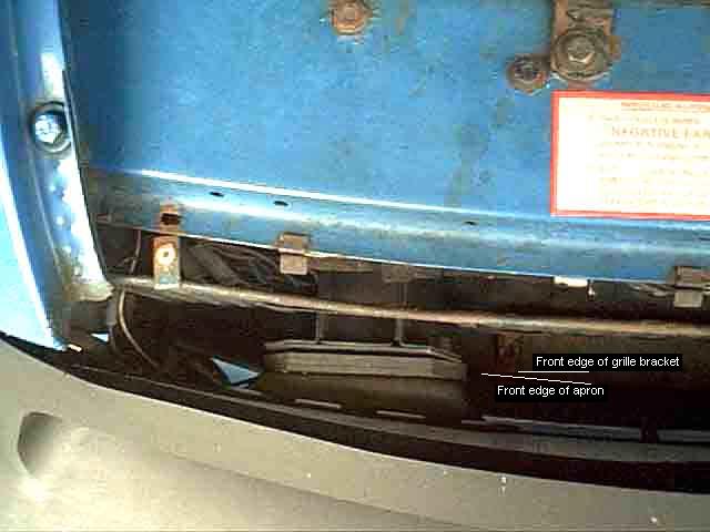 First remove the two large screws from the bottom brackets and the three small screws going through the slam-panel to the plastic sockets in the top brackets
then slide the whole grille forwards, keeping it vertical, just enough for the top brackets to clear the front edge of the slam-panel.
First remove the two large screws from the bottom brackets and the three small screws going through the slam-panel to the plastic sockets in the top brackets
then slide the whole grille forwards, keeping it vertical, just enough for the top brackets to clear the front edge of the slam-panel.
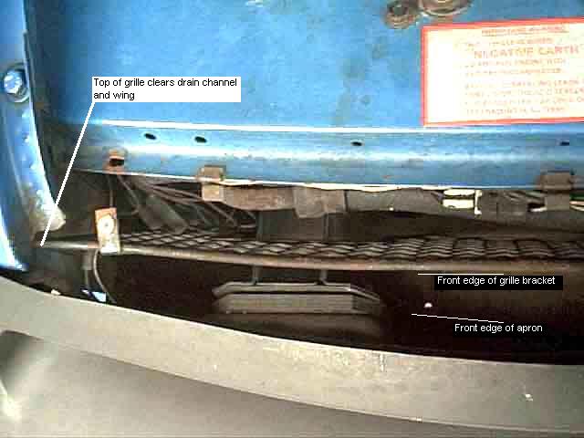 Next tilt the grille by pushing its bottom edge back as far as it will go, this should allow you to tilt it even more by bringing the top edge further forward to clear the end of the wing drain channels and the very front edge of the wings themselves.
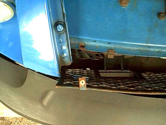 Now you should be able to lift the whole grille up, keeping it square and tilted, with the outer edges of the grill passing through the small gap between the back of the bumper and the front face of the wing. If your gap between bumper and wing is too small to allow this, slacken the nuts securing the bumper to the chassis legs which should allow it to angle forwards increasing the gap.
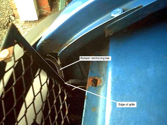 This image shows the vertical edges of the grille and the reinforcing bar for the upper part of the rubber bumper. This bar sits in a channel across the top edge of the bumper, then bends back for a short distance and then downwards. There should be about 1" clearance between the edges of the grille and these bars i.e. they should not interfere with removal at all.
Seat Belts Updated April 2009
Mounting bolts
Belt Types
Inertia mechanism
Belt guides so you don't have to grovel around behind you to find them
GT rear belts August 2013
Seat-belt warning system
Did the MGB ever have air-bags?
Mounting points: Quite a lot of confusion over seat belt mountings from time to time.
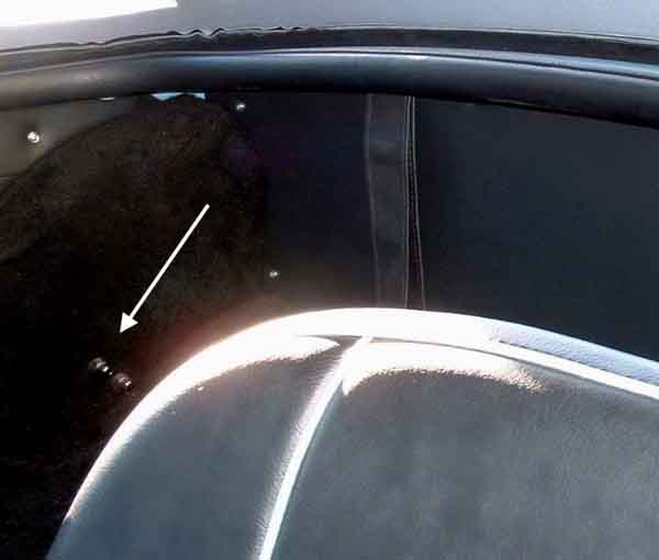 Very very early cars seem to have had two 5/16" studs near the middle of the lower edge of the inner arch. Both these should be used with an adapter plate, one stud is not going to be enough if you really need the belts at any time.
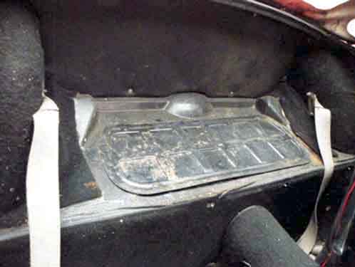 After that a single larger threaded boss was fitted to the rear arch, low down and about mid-way from front to back.
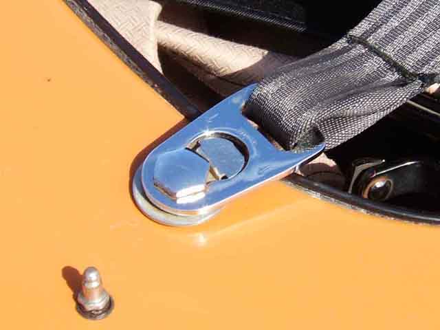 On Mk2 North American roadsters up to December 1971, and on roadsters for other markets from January 1971, mounting points on the tonneau panel were used which necessitated a quick-release device so the belt could be detached each time the hood was raised or lowered or the tonneau cover fitted or removed! The fastening utilised a plastic button, most have probably broken by now and been replaced by inertia reels. When I received my roadster it had inertia reels - but fitted to the tonneau panel. Very inconvenient as these had to be unbolted to raise and lower the hood! This picture was taken on the 2007 New Forest run and shows a metal button which seems to be the only type available now. The Driver's Glovebox Handbook indicates that this quick-release fastening was used on GTs as well as roadsters, with the fastener mounted on top of the rear arch. Quite why isn't known, whilst the roadster did need it to raise and lower the hood that isn't the case for the GT. A friend's 72 GT had these belts but with just a plain bolt on the arch, which meant the belt bracket could come off the bolt without having to depress any locking plate. I first thought this was an error and somehow his car had got roadster belts, but maybe not, maybe it was just the fastener that had broken, and in any event he fitted inertia reels. For those roadsters that have them but unused there is a blanking plug to prevent water ingress.
It seems that when the tonneau mounting point was provided the wheel arch boss was deleted - but only from roadsters, so these cars from November 67 to December 71 only have the tonneau panel mounting point. Presumably this was only on North American roadsters as UK roadsters didn't get the tonneau mounting point until January 1971, when the arch mounting point was deleted from those as well. To use static belts with a fixed shoulder point where your quick-release type are damaged and you can't get replacements, you will have to provide a mount on the inner arch. Probably the easiest way to do this is with 1/8" steel plates either side of the arch panel and bolted through. The belt should come with a spacer/boss that the belt end will rotate around even when the bolts are fully tightened. Only when North American cars got inertia belts as standard in December 1971 and RHD cars in May 1977 was a mounting point reinstated to the inner arch, however now it is right at the back of the arch and just above the chassis rail. The tonneau panel mounting points were probably deleted at this time.
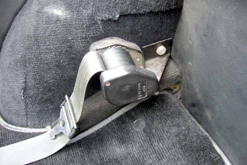 To fit inertia reels to roadsters built prior to the above dates you will need this fitting kit (item 2) from the MGOC (maybe other sources). This shows Bee's inertia reels fitted to the later position using the kit, which entails drilling a hole in the panel. Fitted in this position they do not prevent the hood from folding fully, as some have complained. Securon reels can bolt directly to the vertical panel and be adjusted for correct operation, but this means the belt exits vertically and has to twist through 90 degrees between there and the shoulder and can suffer retraction problems with other stuff in the area, and they cannot be fitted to the top of the GT arch without additional bracketry which compromises security in an impact.
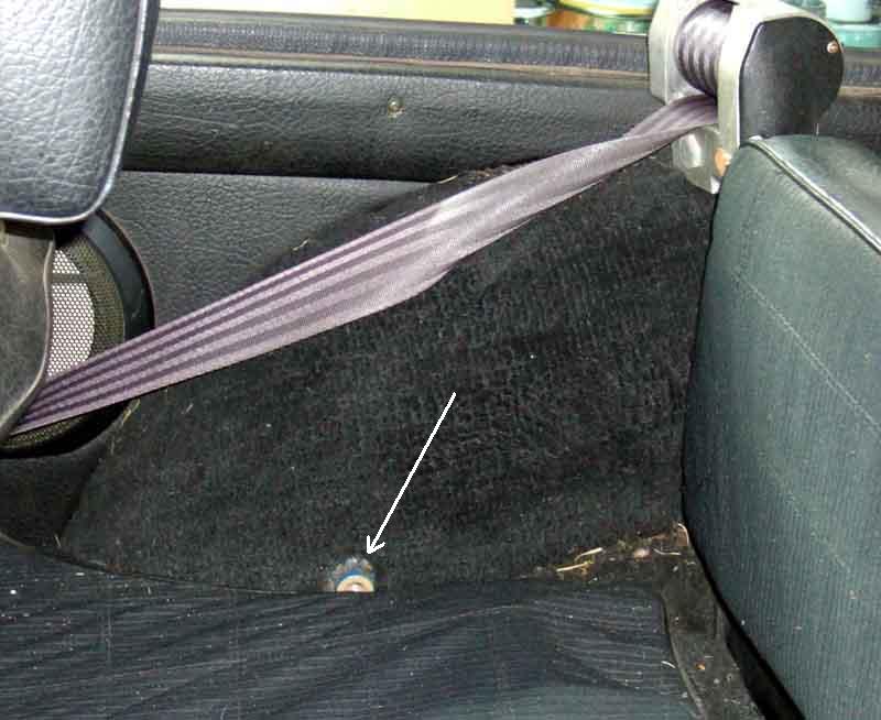 GTs kept the boss in the lower position, but did they always have one on top of the arch as well? It is classed as a four-seater, and late Mk1 shells at least had them, but perhaps not very early models. I've also heard of the roadster-type quick-release static belts attached to those points in a UK GT, but that may have been done by an owner.
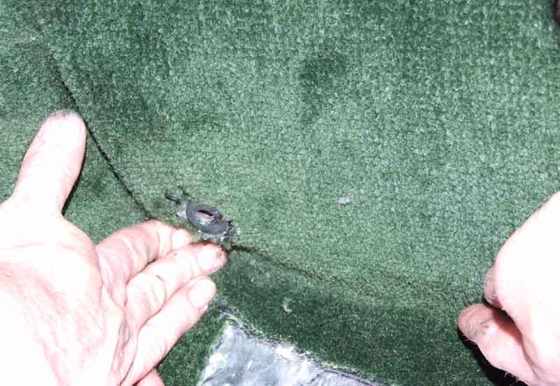 If that wasn't enough the tunnel mounting position also seems to have moved, being further back on early cars compared to later. The earlier position can cause problems with inertia belts with a fixed-length tunnel stalk, being almost behind the seat. Some suppliers do have longer stalks to overcome this.
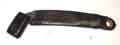 Various tunnel stalk types - floppy (statics) and stiff of various types to enable one-handed fastening.
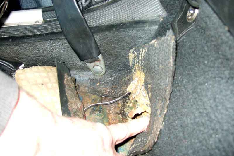 Sill mount position.
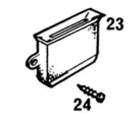 From Feb 72 there was what Clausager describes a 'New seat belt parking cover instead of parking buckle'. However it looks like a socket that the tongue would slot down into, although I can imagine an inertia reel belt could pull it out.
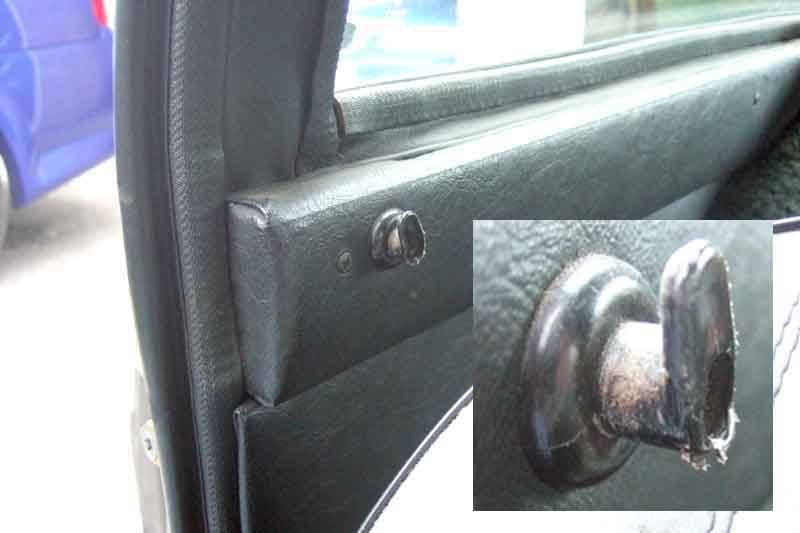 Another fabled gadget - the seat belt hook, fitted from Feb 77 to roadsters and GTs with new Kangol inertia reel belts. This is on a GT, mounted on the rear waist rail, with an enlargement of the actual hook inset. On a roadster the hook was mounted much lower down on the trim panel, below the folded hood frame.
Types: As well as static and inertia types, and different locking features of the latter, there have been a number of different fastening arrangements on both.
As far as inertia belts are concerned Vee came to me with the original belts, and the tunnel part is a fixed length of webbing in plastic sheath that holds the buckle in a relatively fixed position to enable easy one-hand fastening. However over the past 43 years the plastic by the buckle has gradually been breaking away. This isn't a safety issue as long as the belt itself is still sound, but it does mean the buckle flops about and recently one-handed fastening has been getting more of a fiddle. By contrast Bee came to me with PO-fitted inertia reels replacing the original statics. I suspect they came off a late model i.e. 77 and later as the tunnel parts have wires for the seat-belt warning system. But these tunnel parts are a semi-stiff cable encased in plastic, which can be bent and twisted into various positions, and once positioned it more-or-less stays put making one-handed fastening very easy. Interestingly both sets are Kangol Magnet ... without the magnet arrangement used on the statics.
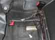 Eventually I'd had enough of groping around trying to orientate the buckle and push the two parts together with one hand. Looking around on eBay I did find the odd tunnel part of the same type, but zooming-in it looked as bad as mine, so I decided to replace the tunnel parts with stiff stalks the same as Bee's. Something to be aware of is that the lengths of the stalks vary, and also the tunnel mounting position was further back on earlier cars meaning they need a longer stalk. Get the wrong length and they will either be too short on earlier cars and hidden beside the seat back, or too long on later cars and the hard plastic socket will be lying across your hip. Found a pair of those OK, the length was given in the advert and was the same as both Bee's and Vee's existing belts (32mm) so I knew they would be correct. But when they arrived I 'discovered' the tongue is different - the originals are rectangular with a square hole and the replacements take a longer narrower one! I should have realised as the differences between Bees and Vees have been staring me in the face for 24 years, but there we are.
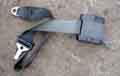 So more eBaying found a single belt with the correct tongue. Complete with bracket for mounting on top of the GT rear arch which is just as well as the existing one is completely different. This is L-shaped as the bolt into the reel is horizontal, whereas the new reel needs one that is basically flat as the bolt through a tab on the real into a boss on the bracket is vertical. Both types of bracket are handed with a slight angled kink to position the reel horizontally in both orientations, as the bolt into the rear arch is at a slight angle from the vertical in two planes. Get the angle wrong and the pendulum device that is one of the two locking mechanisms on these belts will be such that if the car is parked other than on a level surface the belt may lock when you try to pull it out. Although the bracket was marked 'RH' in red felt-tip it was shaped incorrectly for the right-hand side, but a moment in a vice with large grips soon altered that. The original GT brackets were never listed separately, but several suppliers list BMH9514/5 which is a different design and only suitable for the later reels with black plastic housings and not the earlier hammered grey metal housings, and are sometimes supplied as part of a new full belt kits. BHI UK have a number of brackets of various types including flat and angled. They look flat, but also look thinner than either of the brackets I have so will bend easily enough - hopefully not too thin.
As received the belt was fully in the reel, which it normally never is of course, and it just wouldn't pull out when trying it before fitting. With repeated attempts sometimes it would work then lock, and sometimes not at all, which was rather annoying. After much pondering and trying I realised that in my hands, even though I was holding it in the correct orientation it wouldn't work, but held down on a flat surface it did. So even slight wobbling about when hand-held was enough to lock it.
Then onto the main event - the stalks. Went to fit them and realised there is a stepped spacer on the old belts which fits into an oversized hole in the original belt tab, but the hole in the new stalk is only just big enough for the bolt. I didn't want to fit it like that as it would mean several less threads engaged, and if I left it out altogether the bolt bottomed before tightening onto the stalk. Cut the flange off? Or enlarge the hole? For better or worse I enlarged the hole. Fully fitted it pulls out easily, lock with only a slight yank, and more importantly one-handed fastening is now a doddle.
You may well decide to go for a new set complete rather than messing about as I did, but there are several things to watch out for:
- Some come with floppy belts for the tunnels, others come with stiff stalks which as above are much easier to live with.
- There are roadster versions with an angle-bracket for mounting the reel low down on the side of the rear arch, others for the GT with 'straight' brackets for mounting on top of the arch. Many reels can only be installed in one orientation or the pendulum locking device will do its stuff, and the original MGB belts of either type have to be mounted horizontally. Even a slight angle could cause the belt to repeatedly lock when you are trying to pull it out to fasten it if the car is not on a level surface.
- Whilst reels from most manufacturers only function correctly i.e. pull out smoothly if they are mounted in one specific orientation, others can be mounted in two or more orientations and have adjustments so the locking action operates correctly such as Securon. Although these can be mounted in pretty-well any orientation normally without brackets they are best avoided on both roadsters and GTs for the following reason. They have a large additional section on one side of the reel that contains the orientation adjustment. This is fine on the left-hand GT arch, but on the right-hand it means the reel has to be positioned further inboard by quite a margin. It will not fit without a bracket, or even the usual GT bracket, unless you add a second straight bracket between the arch and the original bracket to make a right-angle. Fine in normal use, but if ever they are needed in anger the reel will move forwards as there is no way the two brackets at right angles to each other will resist the force. In the roadster you can't mount them using the standard right-angle bracket as again the extra lump on one side means they will not fit the right-hand arch. You can mount them vertically and use the adjustment feature, but this means the belt exits the reel vertically and has to twist through 90 degrees to go over your shoulder which compromises the retraction, especially with other gubbins in the way such as windstops, non-standard seats, and belt-guides.
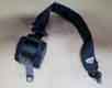 When first looking I only found one belt of the type I wanted, but the day the first one arrived I Googled again and spotted another, so went for that as well. Basically the same shape and complete with bracket, this time definitely for the right-hand side. The only difference seems to be that it does not have the plastic cover that clips over the top of the reel between the two plastic sides. No big deal, I may leave it like that, or may take the cover off the first one if they are identical underneath, or I may make one (I did). Checking Bee's I find they don't have covers either, but are usually hidden by the hood.
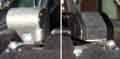 In any event these reels are much smaller, neater and less obtrusive than Vee's originals. But at the end of the day you can pay nearly as much putting together second-hand parts of variable condition as for new. The MGOC M061 (available singly) come with the stiff stalk (not shown, but they have confirmed it) and fitting kits for roadster and GT are available. Watford Classics shows a kit (pair with brackets) for the GT, and Chase MG one for the roadster (pair with brackets, albeit with red belts), both with stiff stalks.
Belt guide:
Added April 2010:
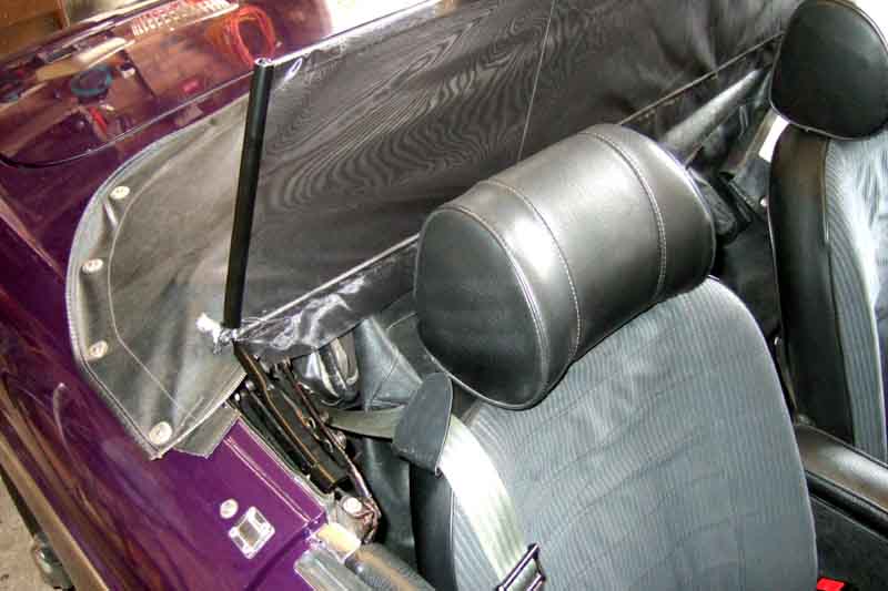 The Navigator has always moaned she can't find the belts every time she gets in Bee (personally I just feel around on the floor behind the seat, but what do I know?). Many years ago we met up with a couple who had some very neat purpose-designed clips attached to the seat, but he knew nothing about them. Browsing on the web showed some for the new MINI at about �60 (and break, apparently) and for BMW and Mercedes at a couple of hundred (what's that about pricing things for what you can get for them?). Pondered it on and off for years, and this Spring decided to do something about it.
All it really needs is a flat strip under the headrest, turned back at the end to retain the belt when released, but allow it to be unhooked easily if needs be. After a bit of thought I realised I could attach the clip to the bottom of the headrest using the tube and one of the screws. Experimenting with card templates showed that something following the curve of the seat back was the most pleasing and effective. I'd been cutting up some square drain down-pipe recently to use as cladding for my wooden garage door frame and had some left over, which seemed as good a material as any. 60mm sides, I shaped and angled the template to fit into a length of that, the end is angled to line up with the main piece when turned back. Using a block of wood either side and clamped in a vice, and a heat-gun, it's quite easy to get a reasonably tight bend for the turned back end, using another block of wood on the back to press it down (it gets hot!), then when you have got it to 90 degrees whip it out of the vice and press it back a further 30 degrees or so.
It certainly holds the belts up and makes them easy to find over one's shoulder, but with the hood folded it does need to be lifted up and fed through as you remove the belt as the inertia reel isn't strong enough to pull it round the folded hood, and without feeding it back it drops over the sill when the door is opened. The opinion of the Navigator is awaited!
June 2010: Showing a roofer pal the garage door cladding made out of guttering down-pipe I happened to mention I had used offcuts to fabricate the belt hooks but was planning to paint them black. He just happened to have replaced some guttering that morning, in black square-section, and dropped me off an offcut so I made two more from that which look much better.
November 2017:
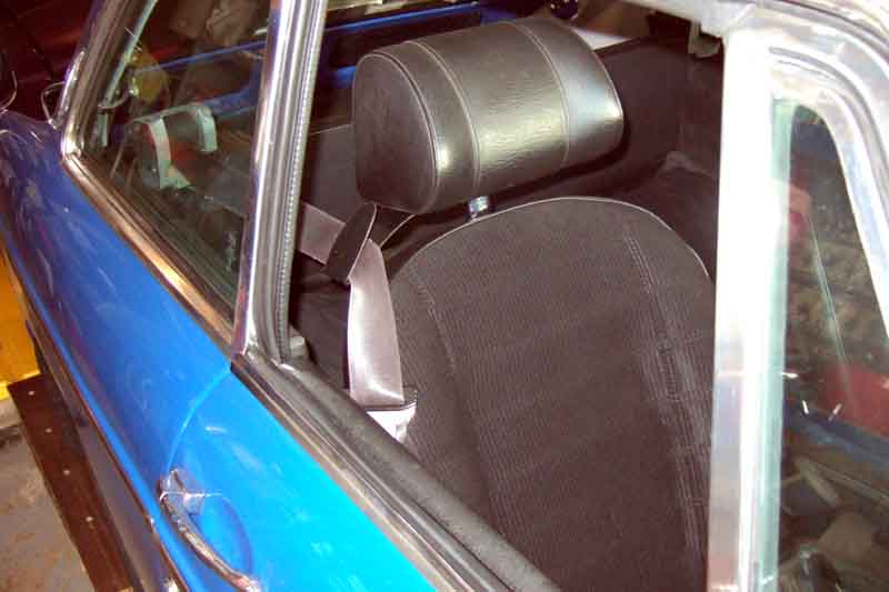 Up till now Vee's belts have always stayed on the shoulders of the seats without any guide, but since recovering them they slip off while parked. So I make another pair, having an offcut of black down-pipe of the perfect length to hand. However it's needed a couple of iterations to get them to the right shape, as with the higher reels on the GT they were being lifted up out of them while being worn.
GT rear belts: August 2013
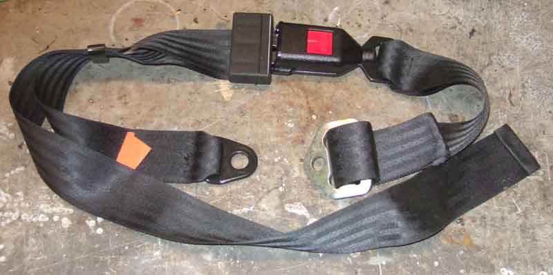 One couldn't possibly contemplate seating anyone in the rear of a roadster, but children in a GT using a static lap-belt is a distinct possibility. Presumably because the GT is classed as a 'four-seater' the factory had to provide rear mounting points, although from when I don't know.
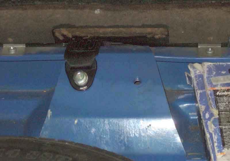 There are two mounting points centrally behind the rear seat back which can only be for rear belts.
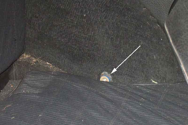 However the side mounting points are not so straightforward. There are bosses on the side of the wheelarch, but these were originally used for the shoulder strap of static belts on both roadsters and GTs. Originally they were quite near the front of the arch, then on roadsters (like my 73) they moved right to the back, but not on GTs (like my 75 V8). Whilst they are usable for a rear lap belt, that half would only go across the front of a child and not curve round them like the central belt, so may allow them to move forwards more in the event of a frontal impact. I think I would prefer to provide another mounting point further back.
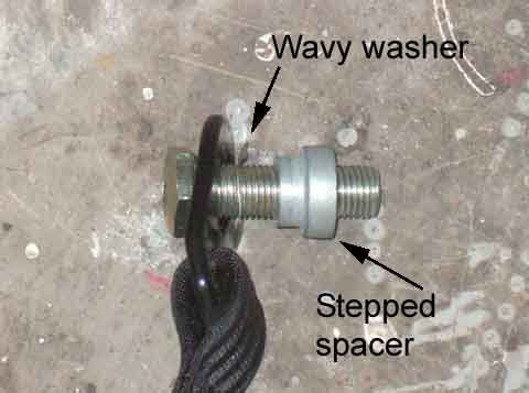 Make sure you use the correct stepped spacer so the bolt (7/16" UNF/20, it seems) can be tightened but still allow the belt ends to swivel, and use a wavy washer to stop the ends rattling. Both fit over the narrower section of the spacer. The wheel-arch boss isn't a through-fitting like the central mounting points (for obvious reasons I hope) so check the bolt will go in far enough to tighten onto the stepped spacer before it bottoms. If it bottoms first then shorten it by the minimum amount. If the buckle half belt-end is angled (like on the Securon) then even though it might seem more logical to angle it into the car, angle it the other way i.e. towards the side of the car so it doesn't jut out and stick in junior's side.
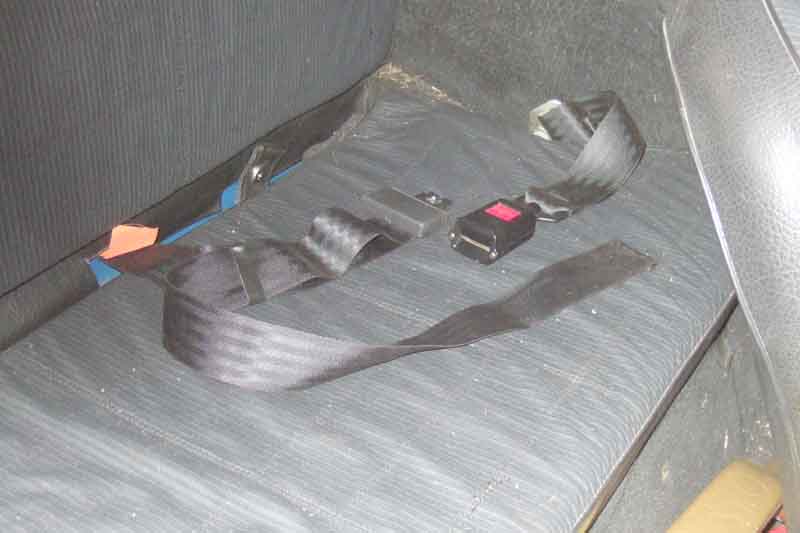 Only a few minutes and a neat installation, to help bring the next generation of enthusiasts along. Strictly speaking the buckle half should be adjusted such that the buckle lies against the hip of the passenger on the buckle side, and the tongue half is adjusted to reach round the front of the passenger. But using the original boss would probably put the buckle across the lower abdomen which is not a good idea, so that half should be adjusted to reach around the passenger and the tongue half adjusted to be much shorter. If a new mounting point for the buckle half is provided at the back of the arch, or even behind the seat back like the central points, the buckle half could be positioned correctly.
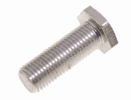 Grade 8.8 is required, 7/16" UNF, either a stepped bolt or a plain set screw used with a shouldered spacer so that when tightened the anchor on the belt end pivots on the spacer, and a wavy washer to prevent it rattling. If the sill or tunnel point should become damaged it may be possible to replace it with a purpose-made nut and strengthening plate welded appropriately. Be aware that some sources of these components state they are M10 even though the vehicle compatibility list includes the MGB and many other BMC/BL vehicles.
Did the MGB ever have air-bags? January 2017 It's fairly well documented (although the ARONLINE site that originally carried a summary of all the SSV vehicles has gone offline, it can be found here) that the MGB SSV shown at the Washington DC road safety conference in 1972 had air-bags as well as a wide range of other safety features, less so that they were crash tested in at least one North American spec car. A pal recently sent a link to a 1995 film about the MGB produced by the MG Car Club of Holland in which there is an MG film clip (with Dutch commentary) showing just such a test. You may be surprised to see just how far forwards the 'driver' is thrown - knocking out the screen, but it has to be remembered that originally in the USA air-bags were designed to be used as a stand-alone restraint device, and not in conjunction with seat belts as they have always been in the UK.
Don Hayter in his 'MGB Story' writes about taking an MGB 'tourer' to an American company Eaton Corporation in Turin where an air-bag system "was fitted and wired up in two days, before returning to MG to prepare for a test at Mira. The airbags were inflated at 3500psi by a compressed nitrogen cylinder activated by a speed deceleration sensor (set above 14mph) on the bulkhead. Similar tests determining air bag size, inflation pressures and the effects of deceleration on the crash dummy eventually resulted in a successful system. A film of this development work was made by the BBC's Raymond Baxter and called Safety in Numbers".
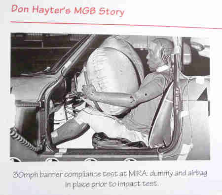 He also has this picture of a MIRA test, this time of a GT with no door so different to the video above. Earlier in the above chapter on Safety Legislation he writes that because of possible rollover problems they had decided to take a GT to the American Transpo72 along with many other European manufacturers to demonstrate various safety systems, in the shape of the MGB GT SSV1. Consequently it seems odd to have taken a 'tourer' to have air-bags fitted, perhaps faulty memory.
Once you have the nuts and washers off the studs you can lever the trim off the other fastenings. For the wings start at the stud end and with a combination of lifting away and twisting you should be able to pop the trip off each fastener in turn. If taking strips off good paint watch it doesn't jump off the last one and scratch the paint. For the door strip i.e. no stud-plate at one end lever carefully with a screwdriver against a wood block resting on a cloth to protect the paint, and with one end free you should be able to lift and twist it off the others as before. Drill out the old fasteners, which are held on with aluminium pop-rivets of about 2mm in diameter. You may have to hold the cup-shaped washer in a pair of pliers to stop it spinning round with the drill.
 Fitting kits are available containing the full complement of pop-rivets with cup-shaped washers attached and six studs and nuts, sometimes washers too sometimes not, as shown in this picture.
|
September 2023: A complaint on the MGOC forum that the cups supplied today are the wrong size and/or shape and being unable to get the trim onto them. Backed up by others who have recommended this kit from Bresco Vehicle Services.
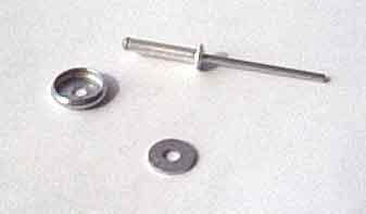 However I have found that if a panel has been replaced from the trim down there can be a double-thickness of metal plus filler, and the pop-rivets as supplied are not long enough to go right through. Consequently they expand inside the hole and can work loose, sometimes when trying to refit the trim. Also if a panel has been skimmed, painted and drilled a couple of times or more the holes can become large and uneven, so again the pop-rivets don't expand behind the holes but inside. I bought some long-reach rivets and transferred the cup-shaped washers over, then used an appropriately-sized washer behind the panel, so not only did the pop-rivet go through a skim of filler two panels and a washer, but it also secured firmly behind the washer no matter how large and irregular the hole was. The cup-washer removed from the original pop-rivet, a long-reach rivet, and a suitable washer can be seen in the picture.
When preparing to fit new fasteners to the body hopefully the painted holes will be large enough to accept them. But if not, slightly overdrill the hole and put some paint on the bare edges. In any case dip the fasteners in Waxoyl before putting them in the holes in the panels - to protect against rusting, but with the rear section being riveted into the boot/hatch space it should also seal against water ingress. Even if you have a long-nose pop-rivet gun its nose may be too big to go inside the cup-washer. Don't be tempted to fasten them like this as the rivet gun may expand the washer and make it much more difficult to get the trim on, slip a small nut over the pin on the rivet so the gun bears on the nut and the nut on the cup-washer. Have a supply ready as they jump off and get lost as the pin breaks.
August 2018: Polishing Vee I discovered the front of the rear strip on the passenger side was loose, and it was the fastener that was loose in the body. It didn't take much lifting away to pull it out altogether ("It'll never get better if you pick it") so the whole strip had to come off - and another two fasteners came out of the body as well. Never had this problem with Bee as the holes were so bad I used long rivets and washers from the word go, and these holes seemed good enough so I used the fasteners as is - obviously a mistake. But I had rivets and fasteners left over from the reassembly a year ago so it didn't take long to replace the three, dipping into Waxoyl as always. It was only re-reading this afterwards I realised I hadn't used the little nut as a spacer, and they came to no harm. One new tip concerns the point at which the pin shears. Initially one has to use the tool to press the fastener against the body while squeezing the handles. But if you are still doing that when the pin breaks the tool can jump off the fastener and hit the paintwork. There are many ways to prevent this, but I found that as I progressively squeezed the handles I kept testing the fastener to see if it has started gripping the body. When it is, i.e. it isn't loose, I carry on squeezing but now I'm gently lifting the tool away from the fastener. So now when it breaks the tool jumps away from the body, instead of towards it.
Before attempting to fit the trim to the car go carefully over the edges and make sure there are no sharp flashings that will cut into the paint, and paint the backs with Waxoyl.
To fit the trim put the top edge on top of one of the middle fasteners, and with a block of wood to spread the load resting against the strip over the fastener strike the wood with the flat of your hand and the lower edge of the strip should pop over the fastener as well. Having done one, check the ends are where you want them to be relative to the vertical edges of the panel, and for the front and rear strips at least fit and tighten the stud plates to hold the strip in place while you do the rest of the fasteners, working out from the one you have already done.
Sill Construction and Drainage Added January 2008
Tread Plates
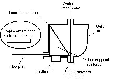
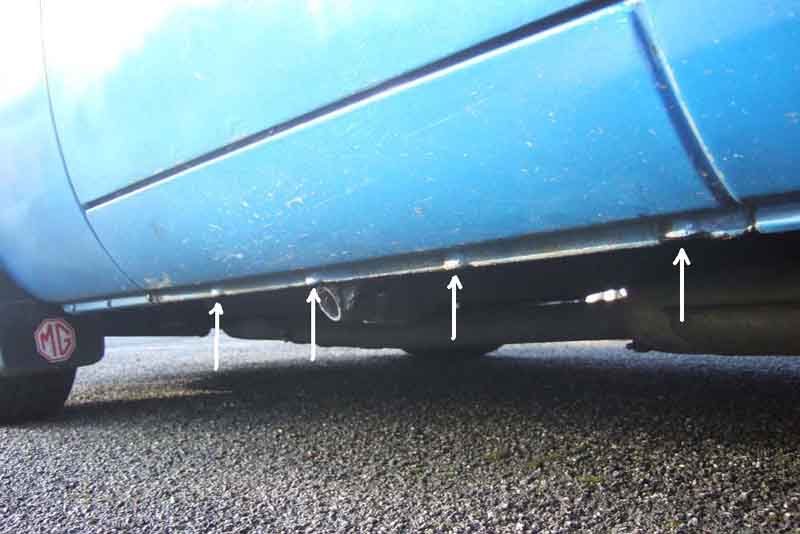

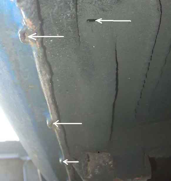 Chatting to someone about treating the very narrow gaps between the lower wing sections and the front and rear of the sills (see 'Quarter-panel Replacement' above) we got on to the subject of sill construction and drainage, which lead to me making a drawing and taking some photos, click the thumbnails.
October 2019: Kelvin Dodd of Moss US writes:
March 2024: Incidentally I have been asked whether the sill and A-post form a right-angle or not. I'd have said 'yes', but using a combination square it seems to be slightly less as the ruler touches the top hinge about 5mm short of the bottom hinge, on the driver's side of both my cars. They both have stainless tread plates, so some scope for doubt.
January 2020:
 SP Brown on the MG Enthusiasts forum posted a drawing and a picture of a factory mono speaker being mounted under the glovebox on cars that had the later centre console.
July 2022:
 An installed picture from Mark Denny.
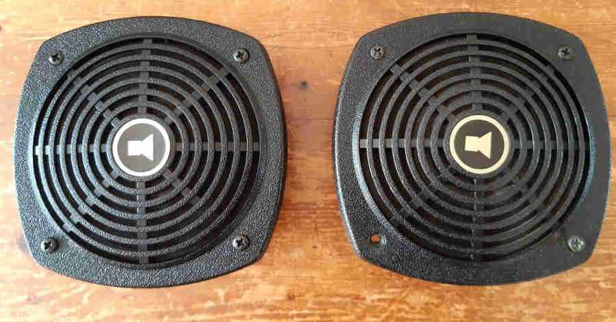
Stereo speakers were factory-fitted in the doors on American cars from 1977 model year on but only in 1979 and 1980 on UK cars and maybe all RHD.
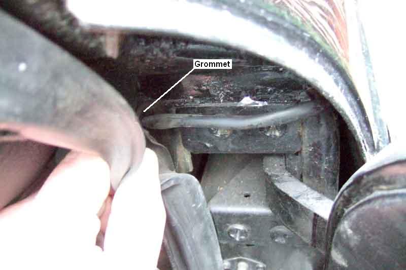 Another question is how the factory routed the cable into the doors from people who want to retrospectively use that location, the attached images show how this was done. The cabling may be in position on later cars before they got the speakers.
Where to mount stereo speakers on earlier cars is a question that often crops up. A PO of my roadster had cut holes in the rear bulkhead but as I didn't intend to have a radio I welded them back up. The V8 came with them in the trim panels immediately behind the door opening but this did entail cutting into the metal panel. OK on a GT but not ideal in a roadster, however smaller speakers or ones that project further may fit without cutting. Surface mounted speakers could also be positioned on the parcel shelf in the roadster, but would need to be detachable to access the battery.
July 2022:
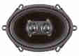 If you don't want to go to the trouble of installing dual speakers around the cabin but want stereo output from the early centre console you can use what is known as a 'dual voice coil speaker'. The 'voice coil' is what the output of the radio is connected to, flapping a paper cone which makes the noise you hear. Conventional speakers only have one voice coil, fine for mono, but only output one channel of stereo. You might think you could connect two stereo channels to a single voice coil - parallel connection, but stereo output stage impedance (resistance) is supposed to be balanced with the speaker resistance. Parallel connection causes an imbalance which is likely to introduce distortion, if not damage to the stereo at higher volumes. As it's name implies a dual voice coil speaker has connections for both channels and outputs stereo from a single speaker unit, albeit with not much separation between the channels. Not much point in using one of these under the glovebox as mono speakers were when the radio was moved to the centre console.
Herb Adler puts twin speakers in the early centre console.
Sunroof September 2019
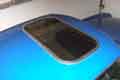 Not the full-length sliding Tudor/Webasto type, but the tilt and remove glass panel that Vee came to me with. Never a problem when using Vee as a daily driver for several years, even though she was frequently used and parked in the rain. However once I got the Celica because of its 4-seats and Vee became a fair-weather car the only time she got wet was away on walking weekends and the like, which being mainly Scotland, Wales and the Lake District was most of them, and that's when it started leaking. And depending on whether I turned right or left after driving off determined whether the passenger or I got a soaking from water lying in the sunroof frame and on top of the sun visors.
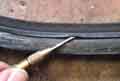 The seal had obviously failed in some way, but the glass still seemed to be closing down onto it. I looked closely at the seal in-situ and the top has a definite surface profile, which turns out to be a very thin flap, which probably stuck up a little way when new but now lies flat. No name on the sunroof anywhere, and Googling shows nothing of that type or size, being either too big for the roof or smaller than Vee's aperture. Googling for foam strip as a possible replacement also drew a blank at that time, so it was just something I or the passenger had to live with.
 When she was repainted in 2016/17 I took the sunroof out completely - an interesting process, which involved pulling the seal out of the frame - carefully - to expose the fixing screws, removing them and lifting out the frame, then teasing out the securing blocks that lie between the roof skin and the headlining. I got them all out, and more importantly got them all back in again later on, which the original fitter obviously didn't as I found an extra one in there! The seal is basically square-section, although the base is narrower than the top, with the outer edge tapered from one to the other and the inner vertical. When I refitted it I decided to pack it out a bit with self-adhesive flat strip about 1.5mm thick normally used on UPVC windows and doors, and used non-setting windscreen sealant all round the upper edge of the seal to the frame, but it still leaked. This time I decided to try and find out just how it was getting through, so stuck some blue paper towel inside the car under the sunroof all the way round, and masking tape round the external frame with one edge sticking up to make a kind of bath, and poured water in. Waited a while but nothing came through, so left it for several hours. On my return all the water had gone, but there was nothing on the blue paper - ? But then I opened the sunroof and pressed the seal down with my fingers ... and water oozed out! So the seal had become porous, absorbs water to begin with, then once saturated starts dripping through, so it really does need to be replaced.
More Googling and this time I find Delta Rubber with many types of material, shapes and sizes, including 'Expanded neoprene/EPDM (Ethylene Propylene Diene Monomer) black expanded closed cell sponge strip' in various width and thicknesses. They supply free samples, so I ordered some 20mm wide by 12mm thick. Ideally 22mm would have been better but there is a big overlap to the glass panel, and 14mm thick but 12mm is the biggest they do, and I can always pack it out as before. When it arrives I give it the water treatment and as described it isn't porous, so decide to go ahead. Back on the website, where I notice they do self-adhesive as well as the plain samples I requested, and that is up to 15mm thick so much better. Only available in 10M lengths, and all I need is 2.2M! So ask if they could do me 5M hoping to halve the cost, but by the time P&P has been added to both it's only �1 cheaper! Look in detail and see that basic P&P off the web site is �4, but they have quoted me an enhanced delivery at �10 as well as it being three-quarters of the price for half the quantity. Ring them up and they say the enhanced option is the only one they do, even if I order online specifying the basic option. So for the sake of �1 extra I order the 10M online and it arrives two days later.
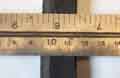 Pull the old seal out, and spend a couple of hours scraping the additional 1.5mm strip off and cleaning off all the old sealant and adhesive with white-spirit. Cut a piece of seal off the roll and drop it in, and realise the base of the frame is narrower than the top, which is why the seal is tapered the way it is, so the new seal doesn't sit flat in the bottom but is tilted inwards. Decide to cut that corner off the new seal, craft knife doesn't touch it, but scissors do and that is a much better fit. So cut off enough to go all the way round plus a bit, and trim a corner off that, which is hard work on the hands doing more than 2M. Lay it in the frame with the ends overlapping, it now lies flat but because it is narrower than ideal leaves a gap at the outer vertical edge to the frame. But I'll use the non-setting sealant round there as before, and that should hold it in place. Left over a couple of nights the corners have remained well tucked-in to the frame even though it is just laying there, so I'm confident once stuck in it will stay there. Before going any further I trim the ends to length and try shutting the roof with a thin strip of paper trapped to gauge how tightly it is pressing on the foam. Quite tightly at the sides and front where the hinges are, and in the centre at the rear where the catch is, but less so working out to the rear corners of the glass. But looking at it from the outside while closing the roof the seal is definitely being compressed by a couple of mm even where it doesn't grip the paper very tightly, so I'm sure it will be OK. It does occur to me though that with the new thicker seal I could be applying significantly more force to the glass and catches than with the original seal and that very thin flap. Not much I can do about that short of profiling the top to leave a narrow ridge all the way round under the glass. But having retested the old seal as well as the new, although the new seal is thicker it is also softer so compresses more easily, and the effort is about the same.
Root out my tube of non-setting sealant ... and find there is about an inch left at the bottom. Maybe enough, but maybe not. So more Googling for the same Indasa Windscreen Sealant, and draw a blank. Email my painter who says to try Tiger Seal or 'PU Panel Bond Sealer', but browsing those they seem to be hardening adhesives and my painter confirms that. So Google 'non-setting windscreen sealant' and get loads of fora saying hardening products should only be used on modern bonded windscreens not classics, and suggesting 3M 08509. Browsing that the 3M site confirms it is non-setting, and I find an eBay page offering 'last one remaining' for �2 whereas most vendors are asking �20 or so. Order that, confirmed, then get an email from the vendor saying it is an eBay error, they couldn't even post it out for that, so I get a refund. More Googling before I order the �20 stuff and I find some Wayside Screen Seal non-drying for �6.50 plus �2.49 P&P. Order that, and will test some to make sure it is non-drying before I go any further. Now the new seal is placed in-situ - with the covering still on the self-adhesive part - and trimmed to size I can still use Vee ... as long as I don't open the sunroof! I decided to leave the cover on the self-adhesive part, as otherwise running a bead round the outside top of the channel as well I'd need to get the seal correctly positioned on two faces, whereas being stuck to the channel on one face only is going to be enough to keep it in position. Probably. Stuck in, glass closed, I push the seal from underneath towards the outside of the frame to press it against the bead of sealant, hoping the glass retains it there until things stabilise. Even so it is showing a gap particularly at the front so I may have to run another bead of sealant in there, white spirit on a cloth does clean it off the foam quite well as well as smooth it out.
Another task is working out the best way to seal the join between the two ends of the seal. Sticking two test pieces together with superglue, Bostick and non-setting sealant shows the latter is the best. But I'll have to make sure the top of the join under the glass is sealed, which has the risk of it sticking to the glass, so I'll put a small piece of black tape there at least until it has become less sticky.
Sun Visors August 2019
Tonneau Cover Rewritten March 2014:
Hood Cover
Note 'Tonneau cover'. Strictly speaking the 'tonneau' is the space behind the front seats, or sometimes the whole of the interior. From the French 'tonnel' for a cask or barrel. Early vehicles sometimes had rear seats fashioned from barrels standing on end with part of the side cut away. Also where we get 'tun' from i.e. a large brewing vessel as in 'mash tun'.
There are many variations in the tonneau covers and how they fasten to the car:
 Dash-top - posts or studs: Some covers fasten to three lift-the-dot posts on the dash top, others fasten to two press-studs on the bottom of the screen uprights plus a central post. North American cars with the padded dash (67 on) and the 77 and later plastic dash don't seem to have the outer posts, only the press-studs and the central post. Some photos in Clausager show both studs and outer posts on the same car (although one or other could have been added by various owners). He also has photos of RHD cars with the outer ones positioned differently - the right-hand one being either above the fuel gauge or above the overdrive switch. My 73 only has the posts, no press-studs, and the right-hand one is over the overdrive switch. Whereas the cover that came with the car had three post sockets, the replacement has outer press-studs and not post sockets, so I had to add these myself.
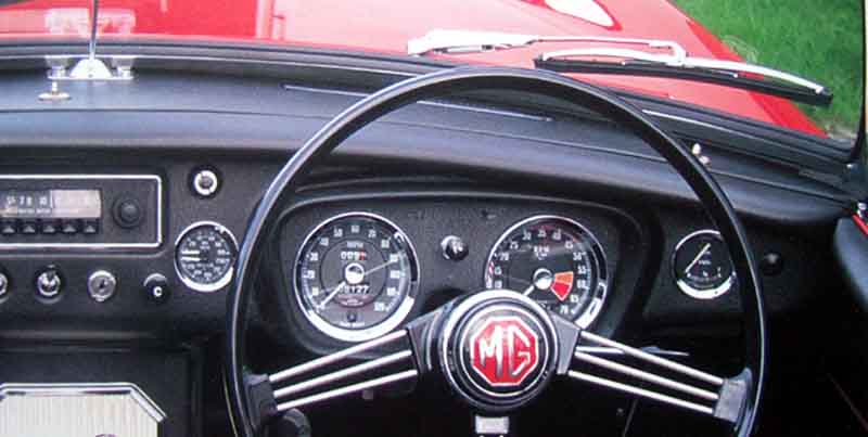 Dash-top - central post: This is positioned slightly left of centre on RHD cars, vice-versa on LHD cars, so a single occupant can drive with the passenger seat covered, but even the exact position of this varies. Clausager shows them either barely to one side of the centre bar, or almost out to one of the bolts. However my 73 came to me with a tonneau cover which fitted the outer posts, but the middle post was out by about an inch. When I restored the car and stripped the dash I swung the post round 180 degrees on one of its screws which put it in almost exactly the right place, which is even further out from the centre bar. The replacement cover also fits this post. The post also seems to have moved fore and aft at least twice.
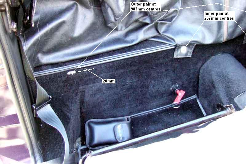 Heel-board: My car has two lift-the-dot posts for a hood cover, or when the tonneau cover is used as a hood cover. My original cover has a full-width flap each side with two sockets, but the replacement only has a tab with a single socket, nearest the tunnel. In fact I could never get my old cover to fasten to the heelboard over the tonneau bars, which is one reason why I have never used them. The new cover does, and looks really neat, but I need the sockets for the windstop, so still don't use the tonneau bars.
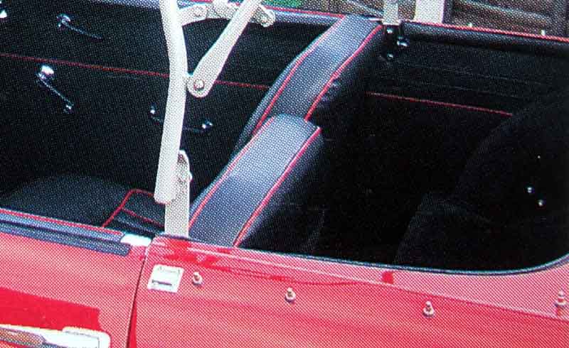 Cockpit rear: Just aft of the door opening there is a square plate which is the socket for a tongue on the hood. Immediately behind that it seems there can be a lift-the-dot post, a press-stud, or nothing at all.
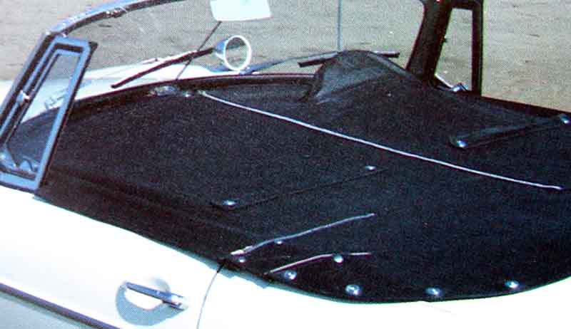 Zips: As well as the long zip up the middle, Some (like my original) have a short zip where the cockpit rail turns the corner, others (like the replacement) have a long zip that goes almost to the middle of the car. Others have no zip at all.
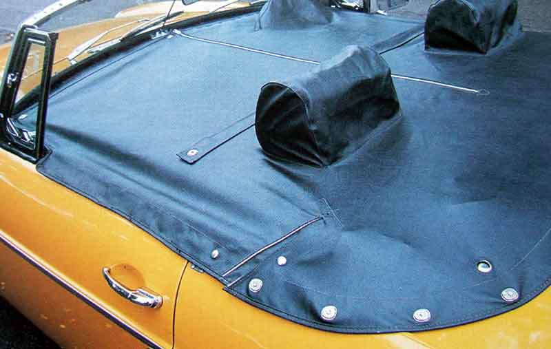 Seat-belts: Some also have a hole in the rear edge for the detachable seat-belts.
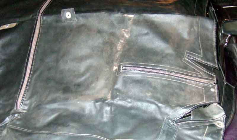 'Darts': Again where the cockpit rail turns the corner, some have just a small slot, others two significant darts.
Someone on the BBS asked about heelboard stud positioning - my inner pair are at 267mm centres, the outer pair at 983mm centres, all four being about 20mm down from the top of the shelf.
The positioning of the fastenings around the rear of the cockpit ...
... and how to get at the nuts that secure them.
Tonneau bars: Aka 'hockey sticks'.
These slot into sockets screwed to the inner panel just aft of the doors. These sockets are also used for the pack-away hood frame and the hardtop and can be installed with both types of folding hood frame.
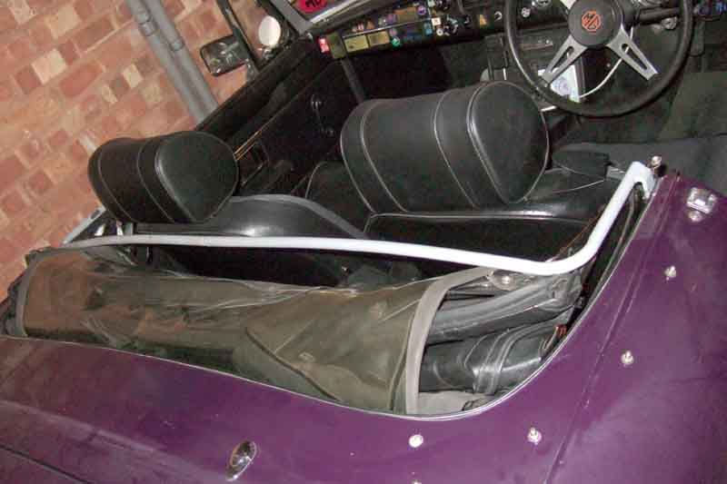 The handbooks I have seen all show the tonneau bars positioned behind the seat backs. Whilst this makes for a neat installation of the hood cover, or the full-length tonneau cover when used as a hood cover, it occurred to me that when one wants to use full-length cover as a cockpit cover against rain, then the bars should be positioned in front of the seat backs. In this position they raise the cover and the rain runs off the sides.
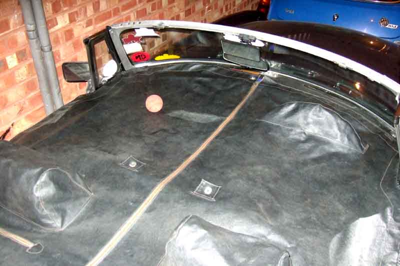 At least they did with the cover that came with the car which is fairly tight. That didn't have headrest pockets whereas the seats have the headrests, so I had to tilt the passenger seat forward and remove the drivers headrest which was a pain, as I use the cover every time I park the car to guard against bird strikes more than rain and always have. Proved wise as on one occasion a Golden Eagle dumped on the cover right over my seat, a real messy one splashing onto the top of the dash and even under the screen! But the faffing with the headrest and the seat was annoying so eventually I got a used replacement from Stoneleigh. However that is looser, and even with the tonneau bars in front of the seats rain pools a bit instead of running off, but still doesn't drip through the zip.
 As its name implies used to cover the folded hood neatly, in place of a full-length tonneau cover. Can be used with or without the tonneau bars in that case. Can also be used to 'hide' stuff behind the seats when the pack-way hood is used, and the tonneau sticks would normally be used then.
| Car | Overall Height | Minimum Ground Clearance |
| CB Roadster (hood erected) | 4ft 1 3/8in | 5in |
| CB GT | 4ft 1 3/4in | 5in |
| V8 | 4ft 1 31/32in | 4 1/4in |
| RB GT | 4ft 3in | 5in |
Vehicle Weights (Updated September 2008)
| Total Weight | Distribution | |||||
| 4-cylinder Mk1 | Roadster | GT | ||||
| Unladen | 1920lb | 2190lb | ||||
| 4-cylinder Mk2 - 1971 | Roadster | GT | Front | Rear | ||
| Roadster | GT | Roadster | GT | |||
| Kerbside Including full fuel tank, all optional extras and accessories | 2303lb | 2401lb | 1127lb | 1162lb | 1176lb | 1239lb |
| Normal Kerbside weight plus driver, passenger and 50lb luggage | 2653lb | 2751lb | 1235lb | 1269lb | 1418lb | 1482lb |
| Maximum Normal weight plus towbar hitch load | 2753lb | 2851lb | 1193lb | 1231lb | 1560lb | 1620lb |
| 4-cylinder 1971 - 1974 | Roadster | GT | Front | Rear | ||
| Roadster | GT | Roadster | GT | |||
| Kerbside Including full fuel tank, all optional extras | 2394lb | 2446lb | 1216lb | 1198lb | 1178lb | 1248lb |
| Normal Kerbside weight plus driver and passenger | 2694lb | 2746lb | 1332lb | 1314lb | 1362lb | 1432lb |
| Gross Maximum weight condition including tow hitch and roof rack (GT) | 2814lb | 2866lb | 1285lb | 1267lb | 1529lb | 1599lb |
| CB V8 | GT | Front | Rear | |||
| GT | GT | |||||
| Kerbside Including full fuel tank, all optional extras | 2442lb | 1207lb | 1235lb | |||
| Normal Kerbside weight plus driver and passenger | 2742lb | 1317lb | 1425lb | |||
| Gross Maximum weight condition including tow hitch and roof rack | 2892lb | 1288lb | 1604lb | |||
| 4-cylinder RB | Roadster | GT | Front | Rear | ||
| GT | GT | |||||
| Kerbside Including full fuel tank, all optional extras | 2448lb (est.) | 2500lb (est.) | ||||
| Normal Kerbside weight plus driver and passenger | 2748lb (est.) | 2800lb | 1456lb | 1334lb | ||
| Gross Maximum weight condition including tow hitch and roof rack | 2868lb (est.) | 2920lb (est.) | ||||
| RB V8 | GT | Front | Rear | |||
| GT | GT | |||||
| Kerbside Including full fuel tank all optional extras | 2529lb | 1268lb | 1261lb | |||
| Normal Kerbside weight plus driver and passenger | 2829lb | 1383lb | 1446lb | |||
| Gross Maximum weight condition including tow hitch and roof rack | 2979lb | 1338lb | 1641lb | |||
| 1977 UK | Roadster | GT | Front | Rear | ||
| GT | GT | |||||
| Kerbside Including full fuel tank all optional extras | 2348lb | 2409lb | 1185lb | 1165lb | 1163lb | 1244lb |
| 1977 North America | GT | Front | Rear | |||
| GT | GT | |||||
| Kerbside Including full fuel tank all optional extras | 2416lb | 1207lb | 1209lb | |||
| All models | Roadster | GT | ||||
| Maximum permissible towing weight | 1680lb | 1680lb | ||||
| Maximum towbar hitch load | 100lb | 100lb | ||||
| Maximum roof rack load | 50lb | |||||
Incidentally the weight of the fully-fitted GT tailgate is said to be 90lb.
June 2020: Note the 77-on UK cars are 100lb (roadster) and 91lb (GT) lighter than the earlier RB cars, and that even hough the North American cars are heavier (by dint of their emissions equipment) they are still 84lb lighter. I'm sure I've read somewhere that the bumper armatures were lightened to improve the handling characteristics of the later RB cars and that would account for it. It's also interesting to note the 7lb difference between UK and North American GTs, I'd have thought the additional emissions kit and additional wiring would have come to more than that, despite the reduction in the number of carbs to the tune of one.
| Drive train component weights | |
| Engine, dry with clutch, 18G/GA | 358lb |
| Gearbox, 3-synch (OD or non-OD not specified) | 78lb |
| Rear axle, banjo, disc wheels | 117.5lb |
| Rear axle, banjo, wire wheels | 123lb |
As far as polish goes Mer is quite popular in the UK, especially with the concourse brigade it seems, but I find it leaves white powdery traces in the crevices of my less than concourse but rust-free black-tulip roadster and these only seem to appear over time several hours or days after polishing, so I keep finding new bits, and keep polishing them off makes me look like an anorak. The benefit of Mer is that it doesn't take any colour off onto the cloth. Turtle Wax does take a little off onto the cloth, which implies it is a mild abrasive, although I have been using it two or three times a year for 12 years or so and haven't worn through yet, but is much easier to apply and polish off and gives a good deep shine. T-cut and other 'paint restorers' should only be used to remove very fine surface scratches, as part of the process of repainting a panel, or on a body that has not seen washing or polishing for many a long day. More frequent use will wear paint down to the primer.
Update 2007: The packaging and formulation of Turtle has changed. Whereas it was a creamy liquid it is now almost like water. It doesn't give the depth of shine on the roadster that it used, and incidentally takes on no colour either. It seems fine on the ZS so is probably formulated more for today's water-based paints than the older cellulose. I have some fairly recently purchased Autoglym Super Resin Polish and that seems to have the creamy consistency that Turtle used to, and gives a better shine than Turtle does now, so that is my product of choice for the moment. Autoglym also sell Paint Renovator (amongst more than 40 products just for retail and cars, plus others for trade, motorcycles, PSV and others!) which is a mild abrasive. This should only be used if the resin polish doesn't remove any surface marks, but is good for removing over-spray on a partial panel respray. An even stronger abrasive, but still less than 1000 grit wet-and-dry is Halfords Cutting Compound. Neither this nor Paint Renovator contain silicones like the Resin Polish do so can be used before painting as well as after.
Update 2008: Looks like what I have is Turtle High Gloss Wax (NLA from the manufacturer), but Turtle Wax Original is also still manufactured so maybe that is the one to go for - when you can find it.
Update 2009: But then again ... while I was using the Turtle High Gloss I noticed the finish was gradually getting duller and viewed at an angle with my glasses on (never a good idea) the bonnet was showing fine surface scratching. "Oh well" I thought, "I never expected the paint to last this long (20 years) anyway". But when I started using the AutoGlym the shine immediately came back and the scratches went, for several outings anyway. I had always been concerned that the original Turtle showed a lot of colour on the cloth, i.e. it was taking a microscopic layer off each time, although it hasn't worn through (yet!) anywhere. The Turtle High Gloss didn't take any off at all, which on the face of it is better for the paint, but as I say the finish suffered. With the AutoGlym, whilst it does show some paint on the cloth, it doesn't seem to be as much as the Turtle original did, but gives a much better finish than Turtle High Gloss. So on balance I'll be sticking with the AutoGlym.
Update September 2016: With Vee repainted my painter recommended Meguiers 3-step system of cleaner, polish and Carnuba wax ... but only after it had hardened for a few months. I didn't think it needed the cleaner which is for 'older' paint, the polish brought it up beautifully, and at that stage I didn't use the wax. It stayed looking really good and dust free until the first time it got rained on, then just a wash was enough to bring it back. A couple of years later it probably would benefit from another polish.
Tree Sap: I haven't needed it on either MGB but my Son's Celica that had been street-parked in London for several years was covered in thousands of very tiny clear raised spots which no solvent I had including WD40, Plus Gas (penetrating fluid), white spirit, petrol, meths plus cutting paste, bug wipe tissues etc. would touch. The only thing that did was 1000 grit wet and dry, but I didn't fancy doing the whole car in that! In the end I found another kind of 'abrasive' in Halfords which was clay-based and like a harder than normal Plasticine. This took the lot off without that much effort and left the surface in perfect condition, and although you could see the 'dirt' from the sap (or whatever) in the clay and had to keep turning it to a clean surface, it removed no paint. Two years since then and it has been fine. Subsequently I get my Son's BMW Z3 M Coupe to look after as well now they have a son and a 'sensible' car and the BMW was languishing unused and getting bashed on the streets of London. This had the same spotting, and the same clay block removed that as well.