


What happens inside?
Setting-up
Pistons, Covers and Dampers
Lifting pins
Needles
Jets
Floats and Valves
Butterflies and Spindles
Throttle Pedal and Cable
Return Springs and linkages
Ports and Vent/Overflow Pipes
Vacuum Port June 2017
Hoses July 2015
Flange Gaskets
Heat Shield March 2018
Dates and Codes
Choke Control
Reconditioning
Plug Colour
V8 - which carb feeds which cylinder?
The MGB was originally provided with HS4 carbs for all markets, the rear having a vacuum advance port. In August 1971 with the then new 18V engine all export markets changed to HIF carbs - 18V584Z for North America, 18V581/582/583Y for other export markets. North American engines now had the vacuum source on the inlet manifold, other markets still from a port underneath the rear carb. UK or 'home market' cars stayed with HSs on 18V581/582/583F engines, then in November 1973 they switched to HIFs on 18V779/780F engines (late CB, November 1973) again with a port under the rear carb, and non-North American export models had the same engines and carbs. With the change to rubber bumpers UK and non-North American export the vacuum source moved to the inlet manifold. In December 1974 North America changed to a single Stromberg/Zenith carburettor on 18V797/798 engines until the end of production. Other export markets continued with HIFs and the same engines as the UK until the 1977 model year at which point all LHD cars were to North American spec - and only roadsters as North American GTs ceased production in December 1974. There were several additional carb spec changes during production.
The SU carb is brilliantly simple in its design, with very little to go wrong. However the later HIF (which stands for 'Horizontal Integral Float', by the way) is a bit more complex than the earlier HS, which I think stands for 'Horizontal Side float'. Why not HSF then? Who knows? The 'Horizontal' in both cases refers to the direction of air flow into the engine, as opposed to the 'down-draft', or 'semi down-draught' you might see applied to some other designs of carb. Visual identification is simple - on the HIF the float chamber is contained within the main body of the carb and actually surrounds the bottom of the jet whereas on the HS the float chamber is to one side of the main body of the carb and has an external pipe connecting it to the jet. Whilst technically the HIF is an improvement over the HS, for a number of reasons there is no good reason to convert to HIFs if you already have HSs, and if you are converting to SUs from Zenith/Stromberg or an aftermarket conversion and have the choice of HSs or HIFs then HSs would be marginally preferable for their simplicity. The diagrams below are of an HS unless otherwise indicated, click on a thumbnail for a full-size image in a different window.
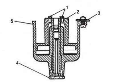
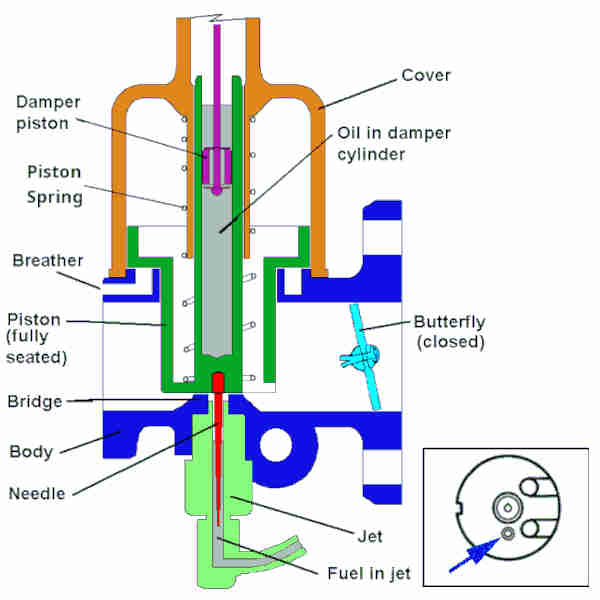 Put simply the SU carb consists of a butterfly valve on the engine side of the carb connected to the throttle pedal and this controls the volume of air being pulled through the carb and into the combustion chambers. However there is another independent 'valve' in the air passage, and this is the large piston which is on the air-cleaner side of the butterfly. The piston is relatively free to rise and fall depending on how much the butterfly is open or closed as will be seen later. Attached to the bottom of the piston is a tapered needle projecting downwards into the open end of a tube (the jet) containing liquid fuel, the height of which is controlled by a float and valve in the float chamber (not shown). With the butterfly mostly closed i.e. at idle the piston will be at the lower end of its travel so it is blocking most of the air passage through the carb. Also the widest part of the needle is in the jet so blocking most of its opening, and therefore little fuel is being mixed with the air, but the ratio of air to fuel (given correct adjustment of the carb) will be correct. With the butterfly fully open the piston will be fully raised allowing the maximum amount of air to flow through the carb, the needle will have its narrowest portion in the end of the jet, so unblocking most of its opening, and the maximum amount of fuel is being mixed with the air, but again the ratio of air to fuel will be correct. Generally this state of affairs will be obtained for any throttle butterfly opening, and hence any vertical position of the piston in the air passage and the needle in the jet. If you look through the carb it is not the same diameter all the way through. Across the top of the jet there is a raised portion the width of the carb - the bridge. This restricts the diameter of the carb throat at that point, which has the effect of speeding the airflow over it and hence over the top of the jet (Bernoulli's Principle). This lowers the air pressure above the jet which is what causes fuel to be drawn up into the airflow to produce the mixture. So as well as the thickness of the needle in the jet controlling how much fuel is drawn up, the speed of the air flowing past the jet is also having the same effect. In steady state conditions although the volume of air increases as the butterfly opens and the piston rises, the speed of the air across the top of the jet remains much the same. However as the piston rises the narrowing needle allows more fuel to be drawn up from the jet even though the speed of the airflow is much the same. Later on we will see what happens when the speed of the airflow increases for the same needle position in one case, and the size of the jet orifice is increased for a constant volume and speed of airflow in another case.
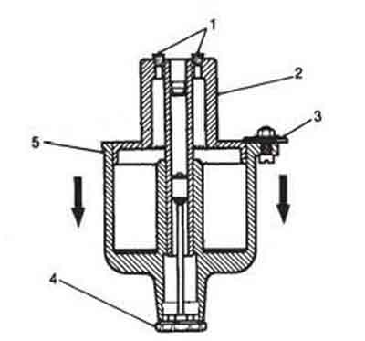
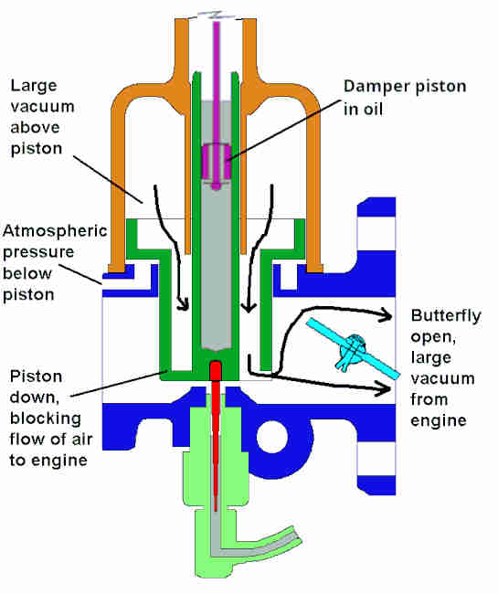 So how does opening the butterfly cause the piston to rise, and the needle with it? With the engine at idle the butterfly is mostly closed and the piston is mostly lowered. But far from 'idling' in the usual sense of the term i.e. doing nothing, the engine is acting like a large vacuum pump due to the action of the pistons in the cylinders. On the engine side of the butterfly i.e. in the inlet manifold there will be quite a large vacuum, which is measured in inches of mercury (in. Hg.), and can be up to 18 or 20 in. Hg. However between the butterfly and the piston there will only be a few in. Hg., and on the air cleaner side of the piston the air will be virtually at atmospheric pressure i.e. 0 in. Hg. Now consider the instant the driver opens the throttle a significant amount, say to accelerate away from traffic lights. The butterfly opens, but with the piston still mostly closed the large vacuum that existed on the engine side of the butterfly is now present between the butterfly and the piston. The piston has a couple of holes on the butterfly side near its base with passages to the space above the piston and its large skirt, so the vacuum is applied above the skirt. Although there is a gap between the edge of the skirt and the inside face of the piston cover it is a very small gap, so virtually none of the vacuum 'leaks' away. Now below the piston skirt there is a passage way to the two breather holes in the air filter flange, so the whole of the bottom of the skirt is at atmospheric pressure. Vacuum above, atmospheric below, causes the piston to rise. This increases the air flow into the engine and raises the needle out of the jet, which increases the fuel flow into the engine, so more mixture in the cylinders, a bigger bang when the plugs fire, and the engine accelerates the car.
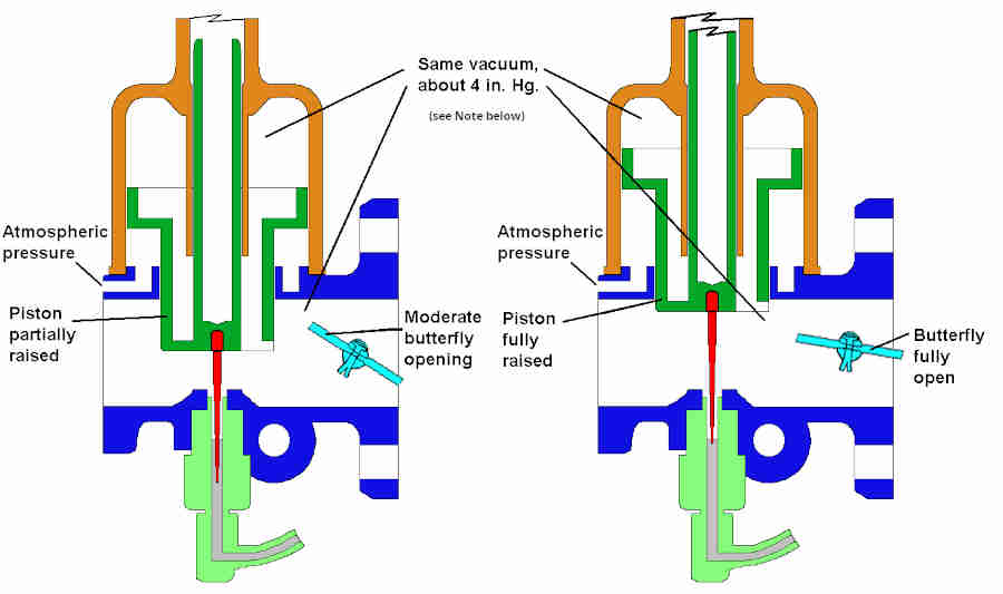 So how does the piston know how far to rise? As the piston rises it 'unblocks' the flow of air into the space between the butterfly and the piston, which reduces the vacuum there and above the piston. This reduces the difference in air pressure above and below the piston, which reduces the force causing it to rise. The piston will continue to rise, and continue to reduce the vacuum above the piston, until it reaches the point where the air pressure both sides of the piston and skirt are largely equal again. It will stabilise at a point where the vacuum between the butterfly and piston, and hence above the piston, are more or less at the same level it was before accelerating. It is this feature that causes this type of carburettor to be called a 'constant depression' or 'constant vacuum' carburettor i.e. no matter how big the throttle opening is under steady state conditions the vacuum between butterfly and piston will always be much the same. If you manually raise the piston further than it wants to go, the vacuum between the piston and the butterfly and above the skirt reduces, and when released the piston will fall back to its previous level. Similarly if the piston is manually pushed down the vacuum between piston and butterfly and above the skirt increases trying to pull it back up again, and when released the piston will rise back to its former level, and the amount of vacuum between butterfly and piston will be maintained.
That is generally the case, but in practise there is a physically large but quite weak coil spring between the top of the piston and the outer cover pressing down on the piston and so restricting its rise somewhat. This is another feature to ensure the correct balance of air to fuel across the range of throttle opening, and means that a progressively larger vacuum is required the higher the piston rises. However the difference in vacuum between idle and full throttle piston heights is relatively small compared to the up to 20 in. Hg or so available in the inlet manifold. The spring strength, carb throat diameter, needle shape and jet size are all chosen to give the correct mixture across the operating range of the carb in any particular application. For a larger or smaller engine, single or multiple carbs, with or without supercharger, etc. the carb throat size, needle shape, jet size, spring strength etc. will all be chosen to give the correct results for that application. You can't just bolt on a bigger carb without doing anything else and expect your car to go faster, indeed it will probably perform worse. Likewise if you make changes to engine capacity, breathing, valve timing etc. you probably won't get the best out of them unless you change the carb parameters as well. What changes to make under what circumstances is a huge subject.
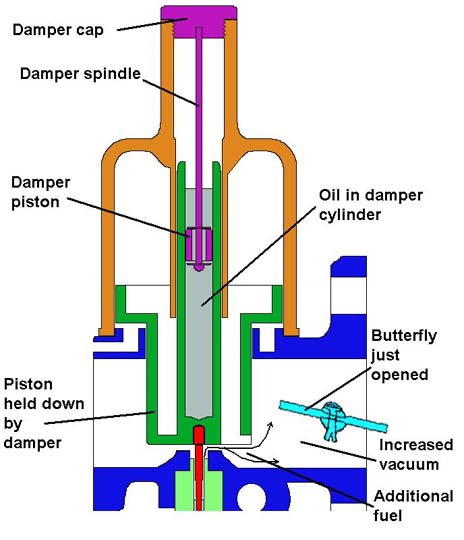 That is basically it. However whenever the throttle is suddenly opened the volume of air passing through the carb is able to increase faster than the volume of fuel can increase coming out of the jet. This has the effect of weakening the mixture, which causes the engine stumble when accelerating. To counteract this on top of the large piston there is a cylinder filled with oil - the damper cylinder. Attached to the outer cover there is a small damper piston sitting in this oil. As the large piston tries to rise the damper cylinder also rises, and because the damper piston is fixed this has the effect of forcing the damper piston further into the cylinder. As the lower end of the cylinder is sealed, and oil is not compressible, the only way the large piston can rise is for oil to be forced past the damper piston. The dimensions of both damper cylinder and damper piston are carefully set to that the oil flows past at a known rate, and hence controls the rise of the large piston. This damps or slows down the rise of the large piston, so that for a short time (a couple of seconds or so) the increased vacuum between butterfly and large piston causes the air flow across the top of the jet to increase in speed, which sucks more fuel out of the jet relative to the volume of air that is flowing even though the needle hasn't yet moved, so enriching the mixture to avoid the stumble. But when the throttle butterfly is closed there is no such need to control the movement of the large piston, so the damper piston is designed to be ineffective when the large piston is falling, so it falls immediately.
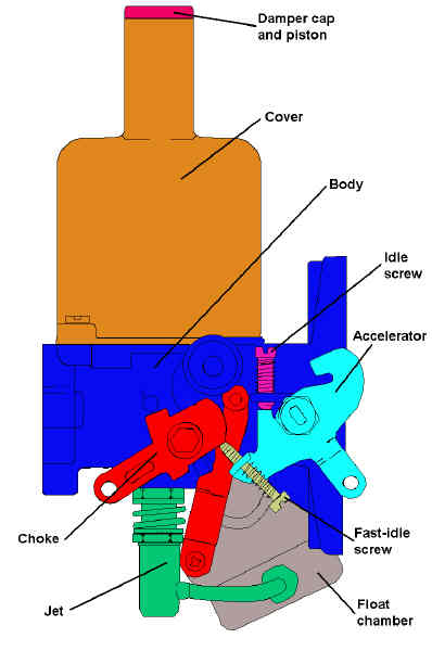 Another occasion when the ratio of air to fuel has to be altered from the norm is on starting from cold. When everything is cold the fuel doesn't atomise as well and so doesn't combust as well inside the engine, so again you get the effects of a weak mixture and indeed the engine may not start at all. To counteract this we have a choke. Well, it is called a choke but that is a hangover from earlier carbs where the air flow through the carb throat was manually restricted or 'choked' as a way of enriching the mixture. In both types of SU carb it is done by increasing the amount of fuel for a given amount of air (rather than reducing the amount of air for a given amount of fuel as in the other design of carb) and so is an enrichment device rather than a choke. But no matter, 'choke' is the generic term, so that is what we shall use. The HS and HIF types differ in how they enrich. The HS has a very simple mechanism for lowering the jet relative to the needle, so increasing the size of the outlet, which allows a given speed of air passing over the end of the jet to draw out a greater quantity of fuel, so enriching the mixture. In the HIF there is a separate valve which opens and adds more fuel to the air stream via separate passages in the carb body. Both types allow the amount of enrichment to be continuously varied i.e. they are not a simple on/off switch. As mentioned before a mixture that is too rich causes a number of problems so you should endeavour to have the minimum amount of enrichment for smooth running. In practice every car is different and you will have to learn how much yours needs under various conditions. As well as varying from car to car it also various according to the ambient temperature and how long the engine has been switched off. Even though the temperature gauge may show fully cold if the engine has only been off for a couple of hours, as opposed to overnight, it may restart with no choke or only minimal choke, you will have to learn. For example my roadster (HSs) needs full choke to start from fully cold then immediately pushed in about half-way, then gradually pushed in further as the engine warms up. By contrast the V8 (HIFs) needs full choke to start and for the first few seconds, then gradually pushing back in as the engine warms. However a pal's 78 (HIFs) is the same as the roadster and others with 4-cylinder HIFs have said the same. Also it is better to drive off immediately after starting and not let the engine warm through idling, unless you have to defrost windows etc., in which case push the choke back to just enough to keep it running, even if it needs more to actually drive off.
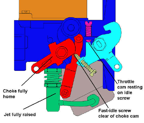 Another feature of the choke control on the MGB is that when correctly adjusted the first 1/4" of movement actually only increases the idle speed - the fast idle - and doesn't enrich the mixture. This is very useful if you are scraping frost,
once it will idle at that amount of choke, even though you may have to add more choke once you drive off. In both carbs the choke control turns a cam which is sitting under the fast idle adjustment screw. As the choke is pulled the cam is turned and it gradually lifts the screw, which opens the butterfly a little more than the normal idle setting. Again the amount of choke to fast-idle is a matter of balance - too much fast idle will cause the engine to race before you have enriched the mixture sufficiently for slow running, which makes for difficult slow running in traffic. Insufficient fast idle may cause the engine to tend to stall even though the mixture is enriched,
so you apply more choke until the idle speed is suitable, by which time the engine is over-choked causing the aforementioned problems of plug fouling and oil dilution.
Another feature of the choke control on the MGB is that when correctly adjusted the first 1/4" of movement actually only increases the idle speed - the fast idle - and doesn't enrich the mixture. This is very useful if you are scraping frost,
once it will idle at that amount of choke, even though you may have to add more choke once you drive off. In both carbs the choke control turns a cam which is sitting under the fast idle adjustment screw. As the choke is pulled the cam is turned and it gradually lifts the screw, which opens the butterfly a little more than the normal idle setting. Again the amount of choke to fast-idle is a matter of balance - too much fast idle will cause the engine to race before you have enriched the mixture sufficiently for slow running, which makes for difficult slow running in traffic. Insufficient fast idle may cause the engine to tend to stall even though the mixture is enriched,
so you apply more choke until the idle speed is suitable, by which time the engine is over-choked causing the aforementioned problems of plug fouling and oil dilution.
Piston Balls March 2013
Drop-test
It is vital not to get pistons and covers mixed up. The original part numbers are for a pair matched in the factory to meet a specified drop-test characteristic, and mixing them up can significantly change the operating performance of the carbs.
There are some misconceptions about covers though, one being that you have to mark the cover relative to the carb body to get it back at the right orientation. Incorrect as the fixing holes are not equidistant round the periphery so each cover can only go back in one orientation. Whilst two of the holes are either side of the intake, the third one has to be one side or the other of the port on the engine side otherwise it would project into the port.
Another one is that you must mark each cover and piston so it goes back on the right body. Ideally yes, but not strictly correct as within each era of carb there is only one part number for each cover piston/assembly so they can be fitted to either the front or the rear carb.
 The interesting thing is that HS carbs and early HIF carbs have a breather rib in the cover neck, and that rib faces in different directions - towards the air-cleaner on the front carb and forwards on the rear carb. This is because the fixing holes in the carb body are mirror images with the hole nearest the engine being one side of the port on one carb and the other side of the port on the other carb. So the cover is at one orientation on the front carb and a different orientation on the rear.
 But later HIFs have the both ribs facing the air cleaners, and that is because instead of the fixing holes being mirror images, the hole nearest the engine is to the rear of the port on both carbs, so the covers are at the same orientation. At first I joked that it must have been someone with OCD not being able to stand seeing the offset any more. But that is highly unlikely, and I think it must have been for emissions reasons. Because they are a matched pair to meet a drop-test, unless the piston and the cover were perfectly circular you will get small difference in the drop-test depending on the relative orientation of the piston in the cover, and so you would get different operating characteristics depending on whether the cover/piston assembly were fitted to the front or the rear carb. With how the emissions limits tightened in later years for North America, maybe that difference was enough to cause problems meeting them. And by moving the position of the engine-side hole to be the same on both carbs, each cover and piston could be tested at a known orientation, and that would be the same when fitted to either carb. Maybe.
Breather November 2013
Ball-bearing suction chamber
Retaining clips
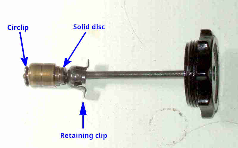
 The damper consists of a brass cylinder on a rod inserted into an oil reservoir in the piston. It has a large clearance to the rod and a small clearance to the walls of the oil reservoir. At the top it is retained by a solid disc, and at the bottom by a circlip, and these two components allow it to damp piston movement when it is going up, but not when it is moving down. When the piston starts to move up the oil in the reservoir lifts the damper up the rod until it reaches the solid disc, which closes off the hollow centre of the damper so no oil can pass through. At that point the piston can only rise further as oil passes through the small clearance between the outside of the damper and the sides of the oil chamber. However when the piston is falling it pulls the damper downwards, opening up the space at the top, and with the circlip at the bottom both ends of the damper are 'open'. Thus oil can move freely through the centre of the damper, allowing the piston to fall without any restriction. Because the damper has to move up a very small distance when the piston starts rising before it starts damping, on very small throttle openings you may detect a slight hesitation as the mixture is not being enriched. On larger throttle opening normal damping covers up this initial hesitation.
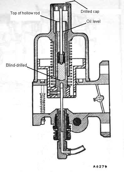 Some confusion over this, and the manuals don't help. HS drawings show the oil level being below the top of the oil reservoir, whereas HIF drawings in the same manuals show it above. I have seen a claim that it has to be above so the outside of the reservoir is lubricated where it moves up and down again against the cover, but if HSs didn't need it why do HIFs? If you do try to keep it above, then you will be continually topping-up, and some people do say they have to keep topping-up. I have maintained my HIFs below, the same as my HSs, for around 90k with no ill-effects so far. All I do is unscrew the plastic cap, lift it up, and press it down again. If I can feel the resistance of the oil before the plastic cap reaches the cover, then I have enough, and the distance before tells me how much 'reserve' I have left. I don't have to top up from one year's end to the next. The oil only needs to reach the bottom of the damper piston in the oil reservoir to do its job, not the top, so to maintain it much above that is overkill.
March 2013: Just having discovered HIFs (and maybe some HSs) have ball-bearing assemblies between the piston and cover, I did wonder whether the higher level would initially drain down and lubricate the bearings, then stabilise, and only be topped-up again at the next service. As long as you only check at the recommended service intervals you will be fine, but if you keep checking weekly then you probably will have to keep topping-up. But as part of my research into the bearings I came across these historic SU technical documents on the SU Burlen site.
The HS document clearly shows the oil level below (a long way below) the top of the hollow rod, and the text states "... pour oil into the hollow piston rod to within about 1/2" from the top of the rod ..." (the text is a bit fragmented, you have to jump from the second line in section 4 to below the drawings in the second column).
The HIF document, Tuning - General page section 4 has three sub-sections depending on whether the suction chamber is 'standard' (i.e. no ball-bearings), has 'early' ball-bearings and the damper retaining clip, or 'later' ball-bearings. Not that it matters, because the two drawings and all three descriptions show the oil level is below the top of the hollow piston rod! So I go back to my Leyland Workshop Manual and Haynes to double-check what they say ... and start to wonder if I should have left well alone!
There is currently a long thread on a BBS about plugs oiling, and oil pooling on top of pistons, and after many posts the person who started it all said he has just noticed that there is oil in the throat of the carbs while they have been sitting on the bench, and wondering whether it could be from the carb damper, saying he did top up the dampers recently. At the moment we don't know to what level he filled them, and if they are HSs or HIFs, but there is another possible cause of complete draining of the oil from an HIF, rather than just what is above the top of the reservoir. And that is that while the reservoir on HSs seems to be blind-drilled, that on HIFs seems to be through-drilled, then plugged. If the plug is faulty or gets dislodged somehow, then that carb could drain completely.
Breather November 2013
 As the piston rises and falls inside the suction chamber the damper oil chamber also rises and falls. Unless there is some way of equalising the pressure the rise of the piston will increase air pressure above the damper, which will progressively resist further rising of the piston. Originally there was a breather hole in the damper cap, which allowed the space above the damper to be kept at atmospheric pressure. However in dusty environments this would draw dust into the carb on each fall of the piston, which when mixed with the oil makes a very effective grinding paste as well as clogging up the works and progressively restricting the free rise and fall of the piston.
Subsequently a web was moulded into the side of the piston cover, which was drilled into the suction chamber above the main piston skirt. These carbs had a non-drilled damper cap and were termed 'dustproofed'. This internal drilling results in suction chamber vacuum being placed above the damper as well as above the piston. This is not a problem if the spring and other components take account of the probable increased 'lift'. Incidentally SU Burlen state in their description of a damper cap that "... some are externally vented (hole in the top) and some are internally vented (angled hole in the Suction Chamber) these are termed dustproof and non-dustproof respectively." Surely they have the terminology the wrong way round - the externally vented being non-dustproof and the internally vented being dustproof?
However the situation is very confused regarding webs or no webs, drilled or not drilled, and vented cap or not vented cap. My 73 roadster has the webs, but they are not drilled. They also have vented damper caps, so probably are correct. But the V8 has no webs, no drilling, and non-vented caps - so how is the space above the damper vented? They also have the ball-bearing arrangement between the piston cover and the outside of the damper oil chamber, instead of the plain and very close-fitting earlier arrangement. So perhaps the ball-bearing arrangement has a larger clearance that supplies sufficient venting. This will also result in piston lift vacuum being above the damper as well as above the piston.
Another thought is that if a vented cap is fitted to carbs with one of these internal venting arrangements, that would introduce an air-leak into the suction chamber, which could limit its rise as the throttle is opened, and definitely upset the mixture.
Ball-bearing suction chamber March 2013
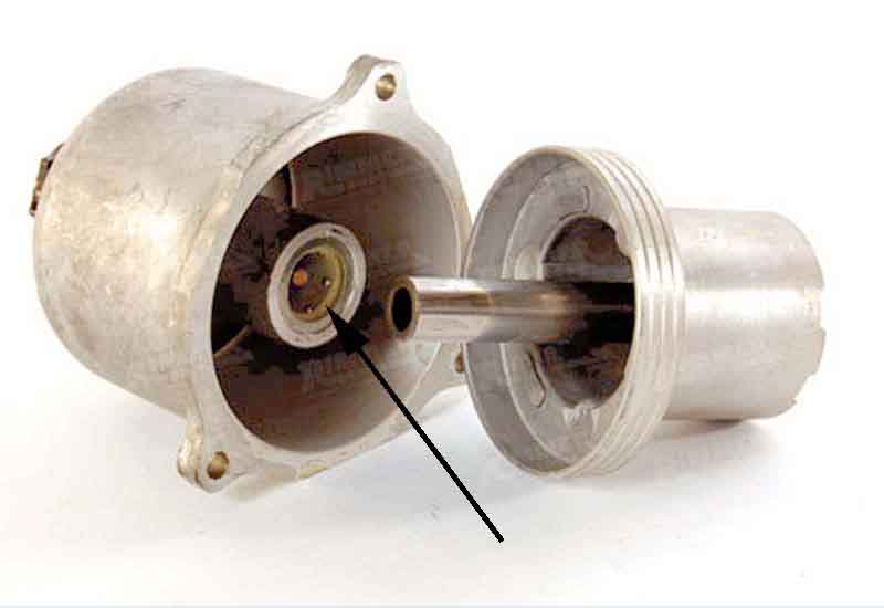 Whereas originally the hollow rod of the piston slid in the cover directly, metal to metal, at some point SU started fitting two ball bearing assemblies, each containing six balls, to reduce friction and sticking as part of their emission reduction developments (see "Ball Bearing Suction Chamber Assembly" here). No clear indication of when, but it has to be in the late 60s/early 70s, and whilst it was definitely applied to the HIF it could also have been in late HSs as well. Originally the balls might have been loose as the V8 Register published a note about the risk, and Geoff Allen also mentioned it in a talk on the development of the V8. Later the balls were held in a plastic sleeve which retained them when the cover and piston were separated, this SU technical article does talk about two types of ball bearing assembly in the section on damper oil level. I have had my V8 HIF covers off and pistons out a number of times and never even noticed them, let alone had ball bearing dropping out, so wondered if I even had them. I found a picture of the cover on the Rimmer site which clearly shows the sleeve and lower balls, and whilst not wishing to remove my covers just for this I did remove the damper cap and peering inside can see the top of the same plastic sleeve between the piston and the cover. This does seem to indicate that mine have the later arrangement, but the same SU document describes that the early arrangement has retaining clips so the damper can only be lifted, not fully removed, whereas the later arrangement does not have the clip and the damper can be completely removed. And mine have the retaining clip! So maybe I've just been lucky not to lose my balls ...
I then started wondering whether this explained why the manuals show the HS damper oil level as being below the top of the hollow rod, whereas the HIF shows it above. I.e. at each service interval you fill it above, the excess runs down to lubricate the bearings, then you top it up again at the next service interval. It could also explain why there are periodic complaints about the HIF 'losing all its oil' if people are trying to maintain the oil level above the top of the hollow rod all the time, and not just at the service interval. But more of this in Damper Oil Level.
Retaining clips March 2013
 These only seem to have been fitted to HIF carbs, and only for a period. Originally the piston and cover assembly was much like the HS in that the hollow rod of the piston slid in the cylinder inside the cover. Then as part of emissions reduction two ball-bearing assemblies were fitted between the two, to reduce sliding friction and hysteresis. It is these that have the retaining clip, which means the damper can only be raised and tilted to one side for topping-up, not completely removed. Subsequently there was a version without the clip, although whether this used a different ball bearing assembly or just did away with the clip, isn't known. The only purpose I can see is to avoid mixing up pistons and dampers, which could result in different rise-times during acceleration for each piston. This SU Technical document (4 Check the piston damper oil level) emphasises that the bearing retainer is not to be displaced from the piston rod, but I accidentally pulled mine out many years ago and it didn't seem to make any difference to anything. Nevertheless after reading this I decided to re-fit it. There are two ways to do this, and if you have the 4-cylinder this is probably the easiest way: Remove the air cleaner, unscrew the damper cap, lift the piston as high as you can with a finger-tip, and hopefully that will lift the top of the hollow rod far enough for you to press the clip back in again. On the V8 it's a bit of a fiddle to remove the air-box then grope around the back of the carbs to lift the piston, reaching across the engine to reinsert the clip, so it's probably easier to remove the cover and piston from the carb body. Then unscrew the damper cap, lift the piston up inside the cover compressing the spring, until the top of the hollow rod has been raised high enough to reinsert the clip. Despite refitting it came out again the next time I went to top-up, so I left it out, and again it doesn't seem to have made any difference.
Drop-test: April 2019
The drop-test measures how long the cover takes to fall from the piston, while holding both inverted, and is performed as follows:
|
|
 |
|
The SU Burlen pages for both HS and HIF say: "For carburetters 38.0 mm (1.5 in) to 47.6 mm (1 7/8 in) bore, the time taken should be 5 to 7 seconds.". Other sources give slightly different timings, but I'd rather go by the SU information
Note: There seem to be different views about leaving the dampers in place, some remove them but SU Burlen specifically says to fit it, with its washer where provided. If you find one of yours takes too long to drop, then try the test again on both carbs but this time with the damper removed. If the two are now very close (albeit dropping faster) then the damper on the slow one is at fault - maybe the shaft is bent, or the (damper) piston not free on its spindle. However that would also be revealed by removing the air cleaners and lifting each piston fully up against damper pressure, then releasing, where both should drop sharply and at the same rate. That check should have been done way before you get into the drop-test.
Ports and Vent/Overflow Pipes: There is often confusion about which hose goes on which port of SUs. If you get the inlet and vent hoses reversed for example, the carb will flood petrol out of one of the ports and/or the jet.
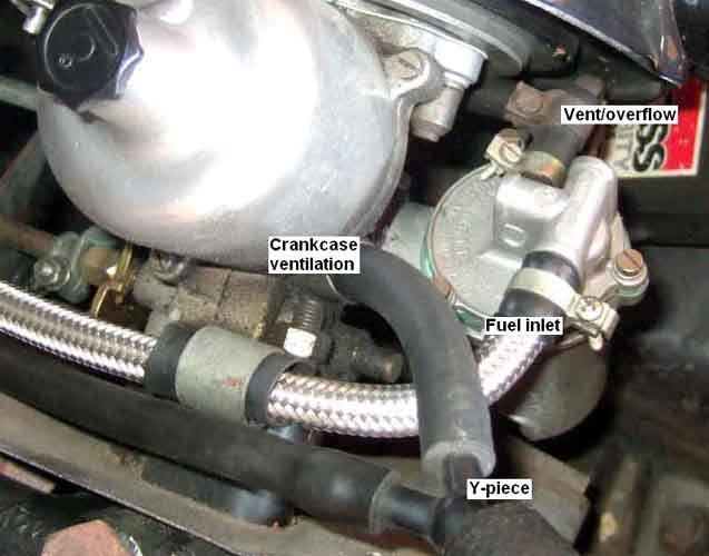
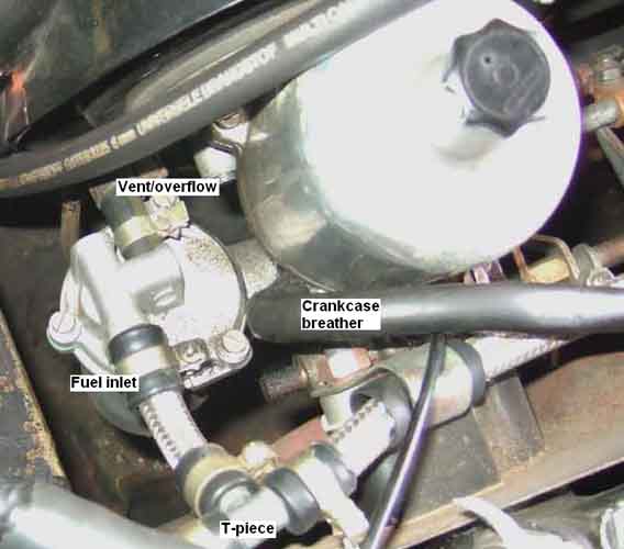 HS carbs are a mirror image of each other (except for the jets which are NOT handed), each with its own fuel inlet and vent/overflow ports. The main fuel feed pipe has a T-piece which feeds the rear carb from a side tapping, the straight-through tapping feeding the front carb. From October 1969 and the 18GG/GH/GJ/GK engines the carbs also had a crankcase ventilation port which removed the need for a separate PCV valve. These are joined together by a Y-piece and connected to the front tappet chest cover port. Click on the thumbnails to see which port is which but basically non-NA cars have the fuel inlet ports pointing straight across the car to the rocker cover, and the vent/overflow ports are the same size pointing straight across the car in the opposite direction i.e. to the left-hand wing. The ventilation ports are larger and point diagonally upwards, towards the front of the car on the front carb and the rear of the car on the rear carb.
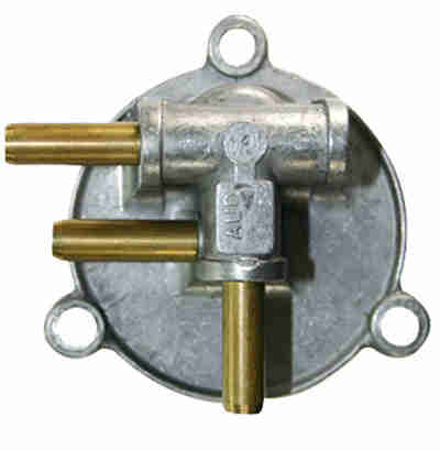 North American emissions-controlled vehicles may have a different arrangement with a three-port float chamber lid on the front carb although this is not listed in the Parts Catalogue. One of the ports is the fuel inlet from a filter on the inner wing, another is a fuel outlet that goes to the rear carb, and the third is the overflow going to the charcoal canister. The rear carb should have a conventional 2-port with fuel inlet and overflow.
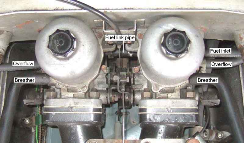
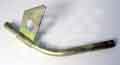
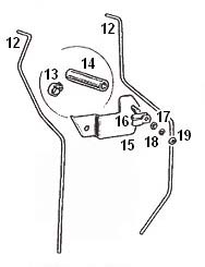 The vent/overflow ports are connected with a short length of rubber hose to two individual steel pipes which carry any overflow safely down past the exhaust. Bee came to me with them just dangling, so I looked closely at a concourse winner of the same year (and colour!) which had them retained by one of the rear engine mount to chassis bracket bolts, so that is how I fixed Bee's. However this means that as the engine rocks the carb end of the pipes moves up and down, but the clipped part stays still, which stresses the short piece of rubber hose connecting them to the carbs. Subsequent research has shown that these run side-by-side to the rear of the engine mount and originally were attached with a P-clip to a bracket (AHH7382 was NLA), which mounts to the side of the block on the lower engine mount bolt. Used until the introduction of the 18V engine in 1971 for export cars, and until November 1973 for UK cars i.e. until the change to HIF carbs when the P-clip was mounted using the mechanical fuel pump blanking plate rear bolt. With the bracket NLA at the time (and access to the lower engine mount bolt restricted with the engine in-situ) I eventually changed Bee to use the engine restraint bracket (also missing when she came to me) which has a convenient hole for a bolt and P-clip to hold the pipes, which allows them to move with the engine.
HIF carbs:
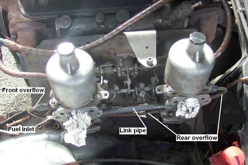
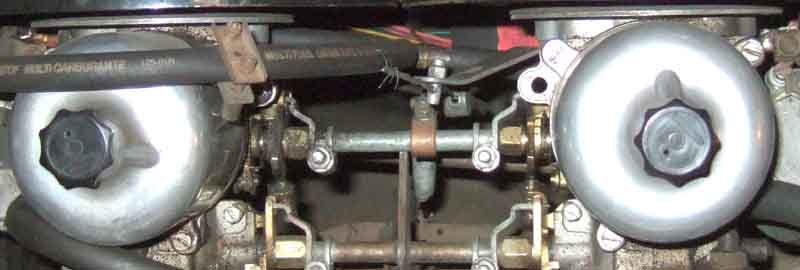
 HIF carbs are mostly a mirror image of each other, but this time both the floats and the jets are handed, and the fuel feed arrangements are different. The jets are colour-coded black and white according to which carb they go in, and I think the black one goes in the front carb. The right-angled pick-up pipe should more-or-less face the butterfly, and the adjuster mechanism engages with a tab on the body of the jet. It might be possible to install the wrong jet with the pick-up pipe facing the other way, but it may also be the case that the cover plate then won't fit correctly. Note that although the manuals and SU Burlen's web site show the jet bearing having a washer above it, a phone call to Burlen elicited the information that later versions did not have it! The fuel feed pipe connects to the front (4-cylinder) or left-hand (V8) carb only, which as well as feeding the float valve in that carb goes straight through the carb body to an 'outlet' port on the other side. A short (very short in the case of the V8) length of rubber hose goes straight across from that port on the front/left-hand carb to a mirror-image inlet port on the rear/right-hand carb. There is a matching outlet drilling on the other side of the rear/right-hand carb, presumably for triple carb setups, but it is plugged on MGB carbs. The crankcase ventilation ports are connected individually via a flame/oil traps to the associated rocker cover. Click on the thumbnails for details of which port is which, but basically the fuel inlet and outlet ports are at the back of the carbs pointing straight across the car, with the inlet on the left-hand carb immediately above its mixture screw, and the blanked-off outlet port of the right-hand carb the same. The vent/overflow ports are immediately in front of those, also pointing straight across the car, and the same size as the fuel inlet/outlet ports. The crankcase ventilation ports are in front of those, are larger, and pointing diagonally upwards as well as across the car. On 4-cylinder chrome bumper cars the vent/overflow ports and crankcase ventilation ports are plumbed similar to HS carbs, but the former are held by a retaining clip bolted to a stud on the engine restraint bracket. On 4-cylinder rubber bumper cars the pipes are clipped to one of the studs for the mechanical fuel pump blanking plate on the block. The V8 has hoses from the vent/overflow ports going being the carbs to a T-piece behind the right-hand carb, then a single down-pipe clipped to a bolt on the bell-housing.
October 2020:
 The 4-cylinder HIF vent/overflow arrangement is much the same as for HS carbs but the V8 is quite different. Hoses from the carbs go under the air-box to a plastic washer tee GWW401 behind the off-side carb. Another short piece of hose goes down to metal pipe BHH1570 which has a support bracket under the top off-side bell-housing bolt, then a longer section of hose goes down past the off-side of the bell-housing. Vee had none of that when she came to me and I had no idea what was supposed to be there, didn't fancy fuel running down onto the exhausts, so I did basically the same with hoses and tee and in the same position, but without the metal pipe to support it all. Apparently these pipes are very rarely seen in the wild, and I can imagine that unless someone remembers to attach the metal pipe to the bell-housing bolt when the engine and gearbox are reassembled out of the car, they won't go back on at all as you can't access that bolt once the two are back in the car!
Flange gaskets March 2017
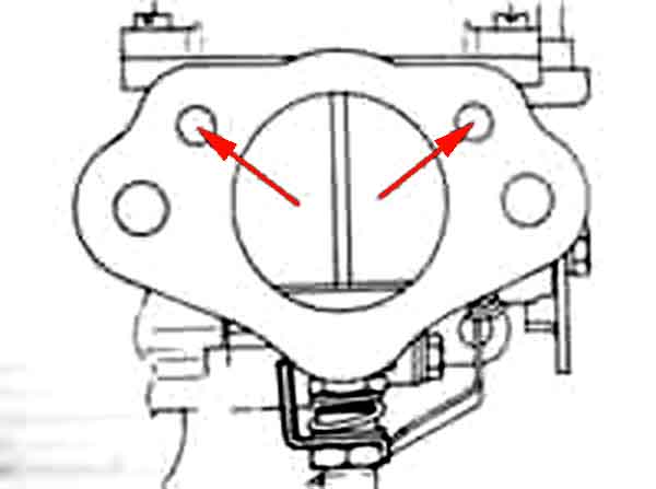 The air-filter gaskets (HS and HIF are the same) are handed and must be installed the right way up. The flange has breather holes that maintain the underside of the piston at atmospheric pressure, so when inlet manifold vacuum is applied above the piston it can rise correctly to deliver the correct mixture. V8 HIFs are different in that there are no less than nine holes in the carb flanges. Again the gaskets must be installed the right way up to leave the breather and fixing holes clear, and that cover the other holes.
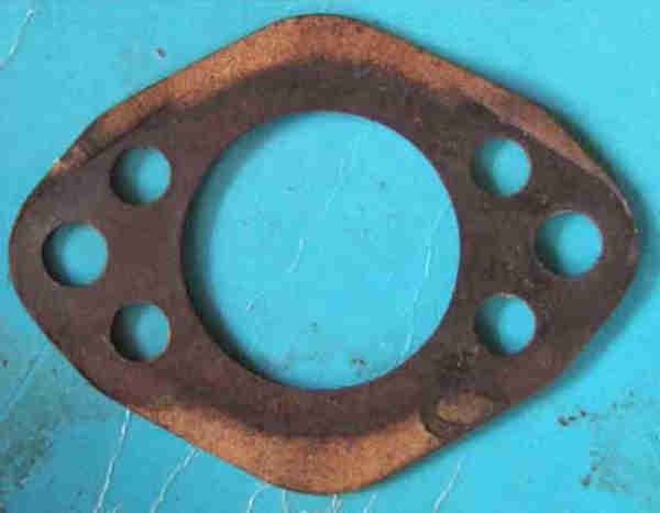 While doing the clutch change on a friend's 78 I found these gaskets, which have holes in both upper and lower positions, and so cannot be fitted the wrong way round. However! You still have to fit the base-plate for the air filter the right way round or the holes will be blocked whichever gasket you use or how you install it! It wasn't obvious from the running of the car that they were blocked, but Keith's car failed it's emissions test this year having passed just a year earlier, done very little mileage since, no changes other than a new choke cable (which was fully releasing the choke) even during the clutch change apart from having the air-filters removed. When I went to setup the carbs for air-balance and mixture I found the filter bases upside down, hence the auxiliary ports were blocked. In the end the balance and mixture were just about spot-on, only the balance under choke was out, which wouldn't have affected the emissions test anyway, so I can only assume I put the filter cans on the wrong carbs hence the bases upside down, and that was enough to affect the reading. Correcting that and a precautionary weakening of the mixture by just 1/8th turn to show 3.8% on my Gastester passed the retest at almost the same figure.
Originally the air-filter cans were clearly handed and as long as you kept them, the bases, bolts and gaskets together as two assemblies you are unlikely to get them on the wrong carbs. But at some point they seem to have been modified so the cans are identical, so if you keep them assembled but mixed up and fit them to the wrong carbs you will get the bases upside down. The Parts Catalogue shows different part numbers for the front and rear cans for all years, but you can definitely fit the later ones on the wrong carbs and it isn't immediately obvious. Originally common to all markets they changed for the 72 model year (from straight intakes to curved?) to three different sets for UK, North America, and the rest of the world (export cars changed to HIF the previous year so it wasn't to do with that). UK changed to use the 'rest of the world' set in November 73 with the 18V 779/780 engines and all twin carb engines had those to the end.
Inlet Manifold:
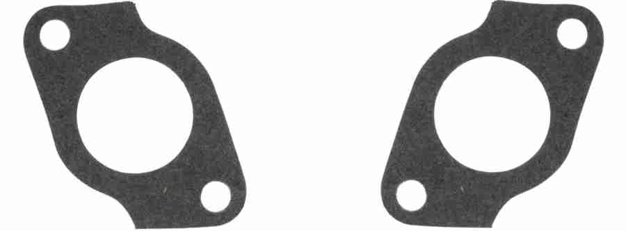 Together with the distance pieces 12H712 there are three gaskets AEC2083 per carb to secure the carbs and heat shield to the inlet manifold. These gaskets are also handed but with these it's not a case of blocking holes but simply aligning the outline with the carb flanges and distance pieces. I think these were originally fitted dry (no fluids normally) but I use a smear of copper-grease on all the gasket surfaces in preference to conventional sealants, both hardening and non-hardening.
One of the biggest benefits of the HS carb over the HIF is that the floats and valves are so easy to access on the HS compared to the HIF, which really need to be removed from the car. The bottom cover on the HIF is also submerged in fuel, and any weakness in the seal can cause significant seepage, enough to drain the float chamber while parked. The HS float chamber lid does have a gasket, but it is above the level of the fuel, so really only protects against seepage if the fuel is sloshing about inside, or if the float chamber should flood due to a faulty valve or float as the overflow port is above the join between chamber and lid.
See here for a bench test of a float chamber.
Floats:
Float Height
All HS carbs used the same float for both front and rear carbs - originally AUD9904, currently it seems to be WZX1300.
North American 4-cylinder HIF carbs used AUD3571 in the front carb and AUD3570 in the rear, currently WZX1510 and WZX1509 respectively.
UK HIF and V8 carbs used CUD2774 in the front/left carb (as viewed from the driving seat) and CUD2773 in the rear/right, however these also seem to use WZX1510 and WZX1509 respectively now.
There are also 'StayUp' float kits for all versions which have a closed cell construction and Burlen claim they are unsinkable. However on one forum someone had one sink, returned it to Burlen, who said it must have been damaged during handling ... which surely makes it no different to any other float ... apart from being nearly twice as expensive!
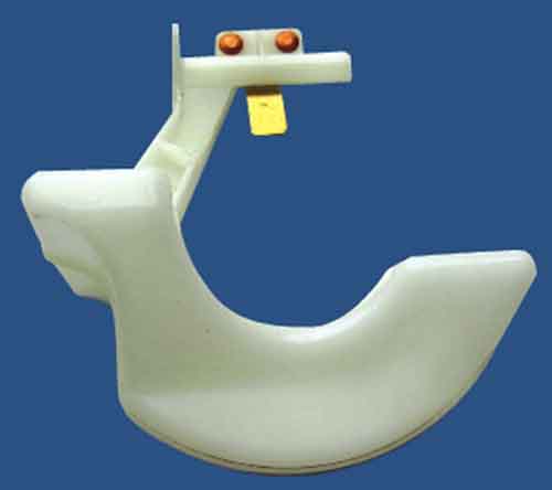 Originally HS floats had a metal tab that could be bent to adjust the height, but in the 1970s all-plastic floats were introduced that were non-adjustable. If these were found to give an incorrect float height washers could be used under the valve, but this only works in one direction i.e. if the fuel level was too high washers would reduce it, but if too low and there were no washers you were stuck. However I found my plastic floats - with no washers on the valves - to be almost exactly in the middle of the tolerance range for height adjustment. Subsequently white HIF floats at least seem to have gained adjustable metal tabs, and black 'StayUp' floats do as well.
If the float cracks it can take in fuel, which makes it heavier, so the level of fuel in the float chamber and hence the jet has to rise higher than it should before it shuts off the fuel flow. This can give rise to mixture imbalance between the carbs and eventually overflowing. If you have repeated overflowing always check the float for fuel by shaking before automatically changing the float valve.
With the lid (HS) or bottom cover (HIF) removed, on HS carbs grip the thicker end of the float hinge pin with a pair of pliers and withdraw to release the float. On HIFs unscrew the hinge pin. On HIFs it is wise to replace the cover seal, they harden in use.
Float height:
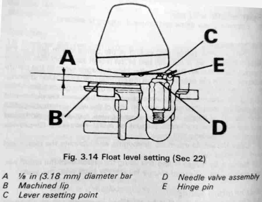 This is given quite a close tolerance in the workshop manuals if not a single value, but according to SU Burlen typically for the HS carbs on MGB it is 3 to 5mm with the adjustable float and steel needle, or 1.5 to 5mm for the 'fixed' nylon float and Delrin needle, and for HIFs 0.5 to 1.5mm. If having problems with a car or carbs new to you or that have had work performed on them and it could be fuel related, check this height. Easy on HS's - just remove the lids, invert, and slide a bar or drill between the lowest part of the float and the machined edge of the lid. HIFs will have to be removed and the whole carb inverted, a straight-edge laid across the centre of the float chamber at right-angles to the pivot i.e. crossing the centre of the 'U' of the float, and estimate (measuring being tricky without wire gauges) the vertical gap between the nearest part of the float and the straight-edge. Note that an excessive gap could be due to an incorrect or faulty valve holding the float too high or too low. If the float is too high it could result in difficult hot-starting in hot weather from heat expansion forcing fuel up the jet flooding the inlet manifold.
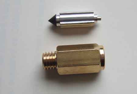
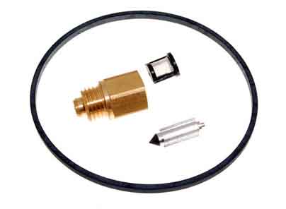
Valves: With the float removed the inner of the float valve should fall out. This has a conical point at one end, and a spring-loaded pin at the other. The outer can be unscrewed with a 11/32" socket.
Original float valve inners were steel tipped against a brass seat. The tip of the inner eventually develops a wear ridge, and this can cause seepage when the valve should be closed, and eventual overflow. Someone in America developed an alternative - Grose Jets (jets?) which used a ball valve, and were said to be superior. They may well have been, but then a Viton tipped valve was developed by SU that was equally as good. Subsequently the Grose products were produced by a different company, and people started finding those became worse than the original SU items, let alone the Viton-tipped versions. Outers for Viton-tipped seem to have a conical seat, i.e. different to the earlier flat seat. This is probably Viton is a resilient material, and the sharp edge of the original seats would almost certainly cause a ridge to be developed in the Viton in short order. It makes one wonder if a conical seat for the original steel-tipped inners would have delayed the development of a wear ridge, if not prevented it altogether.
Three different part numbers were used at various times:
UK 18V HS carbs used AUD9095
US 18V HIF carbs used CUD2795
UK 18V HIF used AUD9095 i.e. the same as the 18V HS carb
V8 (HIF) used CUD 2795 i.e. the same as the USA HIF! These have a larger hole in the outer than my UK 18V HSs, but the V8 inners seem to be compatible with the UK 18V HS outers.
 Viton Tip 0.070" Spring Loaded VZX 1100
Viton Tip 0.096" Spring Loaded VZX 1101
Viton Tip 0.096" (presumably not spring-loaded) WZX 1102. Note that this valve has been known to cause the carbs to overflow when the engine is running.
 "Delrin" .070" Small bore VZX 1099
Viton 0.070" With an additional spring on the outside of the valve plunger WZX 1097
Steel 0.096" Spring Loaded VZX 1095
Viton 0.096" Spring Loaded WZX 1096
Interestingly Googling both V and W versions of these HIF numbers usually shows them with a small filter before the valve.
My V8 uses the larger bore i.e. 0.096, spring-loaded. And whilst originally they were steel tipped it's probably best to get the Viton-tipped now, i.e. WZX 1096. However neither the old or the replacements had filters. As that is the only spring-loaded Viton-tipped, it's probably best to get those for 4-cylinder HIFs as well.
Seepage and Overflow: Small particles can cause slight flooding, getting trapped as the valves would never normally be fully open. Sometimes these can be washed out by disconnecting the fuel pump, running the engine to empty the carbs, then reconnecting the fuel pump. The resulting rush of fuel through the now wide-open valves can dislodge particles. These may not be a problem in HS carbs as the needle to jet clearance is large, and there is room for them to lie in the bottom of the float chamber. They can be more of an issue in HIFs as there are more orifices to get blocked, and they will lie directly under the jet.
Many years ago I started getting overflow from the right carb in the V8. The above trick did not help, so I changed the float valve, but still had the problem. It was only then I discovered the float had fuel in it, impossible to see in the brown float. I tried putting it in hot water to discover the source of the leak, but that, pressure and shaking did not give any indication of where it might be, so replacement was the only option.
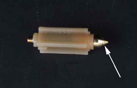 More recently I have been taking some voltage measurements for a pal, with the ignition on but the engine not started for several minutes at a time over a few days. During these time the fuel pump was giving a very occasional tick, as expected, anything less frequent than once every 30 secs, i.e. more than 30 secs between clicks, is not indicative of a problem. A couple of times I thought I got a whiff of fuel, but couldn't track it down or even be sure I had smelt it, even though the garage doors were both closed. Then one time I turned off the ignition, but could still hear an occasional 'tick'. After a short search I tracked it down to a carb overflow hose, dripping onto a sheet of paper. Had that not been there I probably wouldn't have heard it. Looked like the rear carb, and with the overflow hose removed from that carb it was damp, but the front wasn't. Removed the lid and float from it to extract the inner, to find a very definite ridge in the tip. I've lost track of when I had these carbs rebuilt, but it was many years ago. As luck would have it I had just found the unused new V8 float valve from all those years ago when helping another pal with a float valve problem - this time blockage with debris. I could see that the V8 HIF outer had a bigger hole through the middle compared to the roadster HS outer, but didn't fancy using that in case it caused an imbalance. The inners seem identical, so I fitted the new V8 inner to the original roadster outer, refitted the float, lid and supply hoses, and switched on. Left it a minute or more and no sign of any seepage with a piece of blue paper towel (which makes a very good indicator of fluids by going dark) under the overflow port, so refitted the overflows and air cleaners. Turned the ignition on again and after the initial couple of clicks waited ... and waited ... and waited, and eventually after two minutes with no click gave up and declared it 'fixed'. Temporarily perhaps, I've ordered a pair of Viton-tipped, and shall replace both when one or other shows any problems. This was a tiny seepage, much less than would be used at idle let alone running, and does show that if your pump is clicking more often than you think it should, it could take several minutes before anything will come out of the overflow. Even longer on North American spec with charcoal canister where it has to go right across the engine compartment and through the canister and anti-runon valve before it appears on the ground.
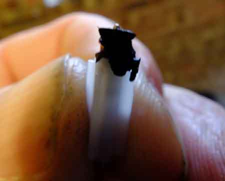 The opposite problem can occur where large lumps of debris can block the valve rather then wedging it open, as in this example from Peter Ugle. The debris is thought to be from the inside of a Gates Barricade hose where it had been pushed onto a very tight port, with rough edges scraping part of the hose inner away.
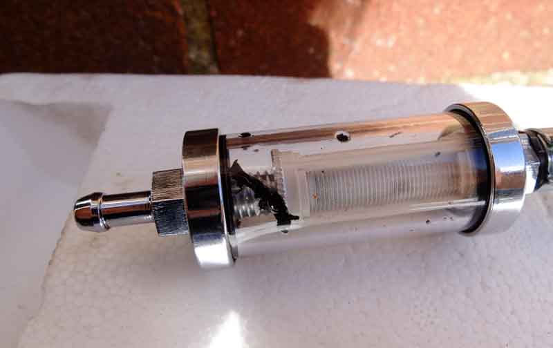 But 300 miles later with new lengths of hose exactly the same thing had happened again, and peering inside the inner liner had been rucked up. Peter slit a length of unused hose and found that even scraping with a finger-nail delaminated it. So it looks like it needs a clearance to be slid on without damage, and even then I can imagine that clamping it up onto the ridges of a filter would chop bits off it. Gates Barricade binned, more conventional hose substituted!
May 2016: Just before Vee's MOT I discovered a leak from where the supply hose replaced just a few months ago attached to the near-side carb, fixed by tightening the clip although it didn't move very much. The day after the MOT while looking at something else I discovered the overflow hose was leaking on the same carb. Obviously the float valve wasn't seating properly (a hang-over from the filter change last year?) and timing the ticks from the fuel pump they were about every 15 seconds. They shouldn't occur more frequently than once every 30 secs, otherwise a problem with a float valve or pump inlet non-return valve is indicated. The first trick is to run the engine with the fuel pump fuse disconnected to drain the carbs, then when the engine has stopped reconnect the fuse in the hope that the now wide-open float valve and high-rate of fuel flow flushes out any debris that might be there. After that clicks were more than 30 secs apart, although less than the 60 secs plus after I had changed the pump hoses. So not leaking now, but that still left the overflow hose to deal with. A few days later after a run - and when cool - I gave up waiting after 2 minutes without a click, but I'll lay a couple in for stock anyway.
Needles November 2021
See here for information on needle selection.
Originally HS carbs had fixed needles and the jet has to be centred on the needle to prevent the one rubbing on the other, inhibiting piston free movement, causing wear and upsetting the mixture. North America changed to swinging/bias needles on AUD326 carbs/18GH engines in 1969. Home market cars didn't get them until 1971 with AUD492 carbs on 18V engines. The jet bearing kits differ between the two - WZX1341 for fixed needles and WZX1442 for bias/swinging needles. The difference is that the jet bearing for fixed needles has a larger clearance in the jet nut to enable centring, that for bias/swinging needles is basically a snug fit in the nut to hold it in one position, the needle moving to fit the jet.
 Fixed needles have a screw that locks it into the piston, swinging have the needle going through a guide AUD4288 and the fixing screw secures that into the piston. The needle is loose in the guide and there is a spring AUD3306 above to keep it pressed down onto the top of the guide.
Jets June 2012
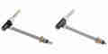 4-cylinder cars have 0.090" jets, V8s (and MGC) 0.100". HIF carbs have different jets to HS and in both cases there are different jets for front and rear (left and right from the driver's perspective for V8) carbs.
There are two different types of jet bearing for the HS4 with different threads which affects how far the jet moves with each turn of the mixture adjusting nut - coarse and fine. However everything encountered on an MGB should be the coarse thread, the fine thread only applies to other marques such as the Mini where it has Waxstat temperature-controlled mixture. Those jets have a red plastic elbow between the flexible pipe and the jet tube instead of black.
May 2024: A thread on the MGOC forum where jet height was discussed and mystification as to why Bee runs well at .045" - which I had rechecked and confirmed whereas it's usually .060" to.085" that is mentioned. I started wondering whether I had .100" jets installed instead of .090" i.e. for HS6! Jet pipes have a coloured plastic band as well as the coloured elbow so I started investigating. Couldn't get a clear statement of what the coloured bands would be for HS6 from either MGOC or SU Burlen, but the latter stated I should have a green band on the rear carb and pink on the front on a 4-cylinder MGB - subject to colour change over the intervening 30+ years ... and I have what appears to be black on the front and yellow on the rear! Browsing SU I came across AUD9148 described as "Right Hand 30? HS jet with black jet head. Identifying sleeve colour is Yellow", not clear whether that is front or rear, so asked Burlen and they said it would be on the front carb of the Special Tuning version. Parts Catalogue Special Tuning HS6 states AUD9148 for the front and AUD9149 for the rear, and browsing that shows it has a yellow band! So either I have HS6 carbs, or .100" jets in HS4s. I'm bound to have set these carbs up from scratch at least once, but I can't recall any issues with the starting position of two full turns down as a starting point, then needing to wind them back nearly a turn to get the highest idle. Maybe I'll count how many turns/flats are needed to wind them up to flush ... or maybe not. Burlen also mention that the correct mixture is set by the the height of the fuel in the jet, which is governed by the floats and valve, plastic floats are not adjustable so there's bound to be some variation between them.
Jet Height: Some recommend getting the starting point for setting-up from a depth gauge and figures of .060" to .085" are given. Personally I've never seen the need when you are going to use the lifting pins and engine note for the final setting, it is only a starting point, and it means removing the cover and piston and putting them somewhere safe, as well as poking things down inside onto the jet. But Miles Bannister recently commented that when checking his he found them at different heights, and when setting them to the same height the car ran noticeably better. My first thought was that using the lifting pin to determine final settings is 'dynamic' based on what the engine is actually doing and not a theoretical measurement, much like dynamic timing is preferable to static, which again is only a starting point. Carbs like anything else have a tolerance in component manufacture, which may well result in very small differences in settings between carbs for an identical mixture, and that would be preferable to a theoretical jet height. But ever interested I decided to check Bee and Vee.
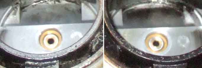 Vee was quite different at .106" for the right carb and .070 for the left. Now unusually this year Halfords had adjusted the carbs to pass emissions only a couple of weeks previously, normally I pre-adjust them up a quarter turn or so then back down afterwards, but this year I obviously didn't do it enough. So I have no idea how the Halfords mechanic adjusted them i.e. one, both, same direction or different. I did have a quick fiddle on my return using the lifting pins, and thought I had got them right, but perhaps not. The difference put one jet noticeably above the jet bearing and the other noticeably below. Wondering if the bearing height is going to be the same as a theoretically adjusted jet I measured both the bearings and found the right at .0735" and the left at .080, so perhaps not. Now one person who recommends .060" for HSs says .085" for the same size HIFs, but the V8 has 1.75" HIFs rather than the 1.5" as used on the 4-cylinder. So I did the same as Miles and split the difference, setting them both to .088. Weather too poor to take her out to try, and check the lifting pins when fully warm, hopefully tomorrow. (March 2013: I don't know whether I ever did this or forgot about it with so much poor weather and not being able to take her out, all I can say is that she is running as fine as ever at the moment).
Butterflies and Spindles: December 2021
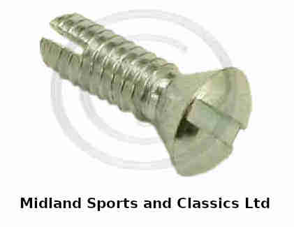 I was asked what thread the butterfly screws were and I didn't know, so did a bit of digging. Several places mention 5BA, but others say that is the wrong pitch and thread angle and the correct screw is 1/8 Whitworth, apparently confirmed by SU Burlen - AUC1358. There are a number of sources searching on that part number so obtaining the correct ones shouldn't be an issue. They are a special screw with a bifurcated end which has to be opened up after fitting to prevent them coming loose and going into the engine. Tighten them with the idle screw fully backed off to be sure the butterfly is fully closing off the throat, double-checking before opening the ends up in case it needs readjustment. Don't bend the ends by more than 45 degrees or they can fracture and the bits get into the engine.
There has been a lot of discussion as to how many return springs were fitted to the SU carbs, in particular whether the choke has one, and it's all quite confusing. The Parts Catalogue for up to September 1976 has one page entitled Accelerator pedal - choke control - all versions except V8' listing item 12 'spring-cable return' AEC2075 qty 2 for UK car numbers 101 to 332032. The next page is entitled 'Accelerator cable and fittings - manual not V8' lists the same item three times - 'spring-return' qty 2 for the same UK car numbers 101 to 332032 i.e. HS carbs which seems to be correct i.e. two cable return springs and two accelerator cam return springs. Then it has 'spring-choke return' qty 1 UK car number 332033-on i.e. HIF carbs; and 'spring-throttle return' qty 2 'except Zenith carb' with no indication of car number which implies both HS and HIF which wouldn't be correct for HIF. For September 76 on 'Carburettor fittings not USA Canada' it lists item 10 AEC2075 'spring-throttle return' qty 3 which is definitely incorrect and item 21 AEC2075 'spring-choke return' qty 1.
HS carbs have torsion springs on the choke quadrants and not on the accelerator quadrants, but HIF carbs have them on both accelerator quadrants. Logically where there are torsion springs additional springs on each carb are not required (as per V8 practice), but they are where there are no torsion springs, plus a cable return spring regardless. So again logically HS carbs need three on the accelerator (two quadrants plus one cable) and one on the choke (cable, which is what mine have), and HIF need one on the accelerator (cable) and one on the choke (cable), and the Workshop Manual does only show two springs. However several cars seem to have them on HIF choke quadrants making three for the choke (including a pal's 78), with others reporting that with only one on the choke it does not return properly. Moss for the HIF only shows one spring for the throttle and none for the choke, and Brown & Gammons do not differentiate between HS and HIF showing 3 throttle and 1 choke which is what Moss shows for HS.
For completeness both Catalogues show one 'Spring-throttle return' with the Zenith carb, the 76-on catalogue also lists one 'Spring-throttle return' with the pedal parts but the earlier Catalogue doesn't.
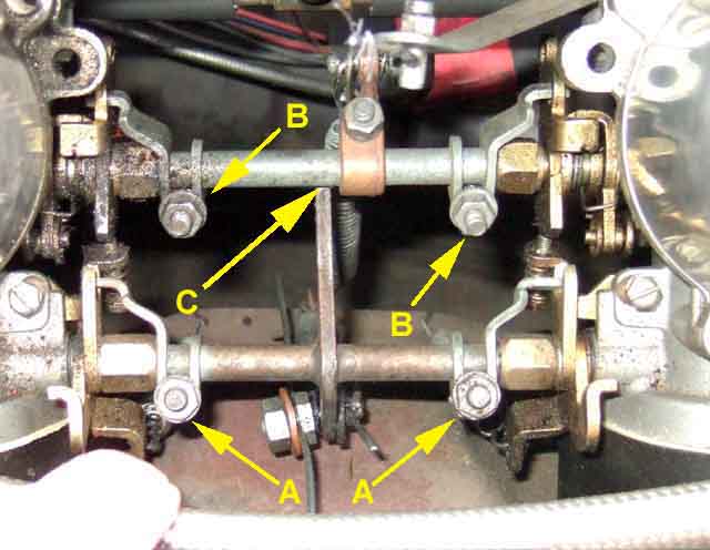 Mine (HSs) originally had four springs with the throttle cable one hooked over the pin of the cable clamp rather than using the correct 'link washer' 12A4. The attachment points on the heat shield may give some clue - the Parts Catalogue for up to September 76 shows it with three tags sticking out with holes in (confirmed by various owners) which also goes to support three springs, but my 73 UK roadster with 48G Gold Seal engine heat shield only has one tag, and four holes on the bottom edge making five potential attachment points in all! However two of them are not holes but slots, so it is possible these have been added later with a hacksaw rather than a drill, which could reduce the original holes to three. But having said that, the slots are actually more logical places to attach the two throttle springs as they have a better alignment. The Parts Catalogue for September 76 on shows four tags, although whilst three are of the same size and look in about the right positions for springs on the linkages the fourth is larger and right off the rear so maybe for something else entirely. My throttle always tended to be a bit jerky on small movements, lubricating the old cable and even replacing with a complete new inner and outer making no difference. I temporarily disconnected the fourth spring and on a short drive it did seem to be smoother. The pedal return pressure doesn't seem to have been lightened to any significant degree, so hopefully there will be no increased risk of sticking. There wasn't, but at some point I did reinstall the throttle cable spring and have not noticed the jerkiness I had before.
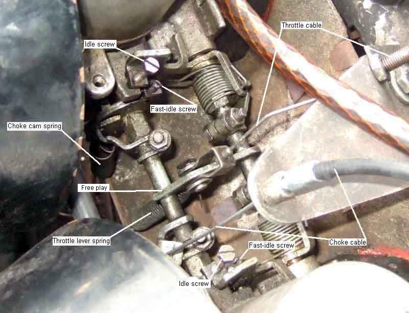 On a friends UK 78 (HIF) whilst there are holes on the choke quadrants and the throttle lever for 3 springs I can't see anywhere to hook a spring on either of the throttle cams. Neither is there a hole in the choke lever for a spring (maybe missing link washer 12A4), and only the front carb choke quadrant has a torsion spring (probably an error). There is only one hole either side in the flange on the heat-shield, assuming these are for the choke springs that leaves nowhere for throttle cam springs. However there are two holes and one tab with a hole in the centre, which suggests two of those could be for the throttle and choke levers as on HSs, leaving the two outer holes for throttle cam springs again as on the HSs, but as I say nowhere obvious on the cams to attach them.
V8:
 Only one throttle return spring - BHH1781 which is shorter than the SU items at a stated 1.75" 'free' length, plus two torsion springs AUD4272 and 4273 on the butterfly spindles and two more AUD4417 and 4418 on the choke spindles. BHH1781 is not listed in the Parts Catalogue for the V8 and no one seems to have one. Similar to the 4-cylinder springs AEC2075 at a stated free length of 2.75", the springs themselves on my two cars are the same length it is only the wire ends that are longer on the 4-cylinder, so it would be easy to shorten a 4-cylinder spring to suit the V8. Whilst my V8 spring is shorter overall than one from the 4-cylinder it is only by about 1/4", not the 1" that is indicated by the stated lengths. Both are barely stretched when fitted to a released throttle which logically seems to be correct, if the V8 spring was 1.75" closed it would have to be stretched at least 1/2" to be fitted. I've never had any indication of throttle sticking open, and there are two torsion springs on the spindles after all making three in all, the same as the 4-cylinder HS (three coil springs) and HIF (one coil spring plus two torsion springs) installations. However BHH1781 is also used on the Stromberg carb which was fitted for several years on North American spec and a couple of suppliers there list it - if they will post it and you can stand the postage cost. At least one of them cross-references BHH1781 with AEC2075 which is obviously incorrect so you need to be careful.
MGOC show it for the Stromberg here (but I can't find it on their web site) in April 2022. At least they did, after finding this for someone and them getting one I got an email saying there was only one left, so I'm afraid I bought it. Well, I say 'bought', but after a week it hadn't turned up. Complained, and they said they still had one on the shelf so it obviously hadn't been sent, and to order it again. But of course because it had been the last one it had been processed as 'sold' so that page showed 0 available and no 'buy' button! So back onto them and they corrected that, so I was able to purchase it - but it was 50p dearer!! That's neither here nor there but I moaned about it anyway, and they said I should have contacted them direct!!! Maybe they should have got it right - three times. At least this one came in two days.
Dates and Codes January 2023
| Year | First Prod | Type | Spec | Date Code | Example | Notes |
| 1962 | 5/62 | HS4 | AUD52 | X | 9X10 | Small hole for float bowl |
| 1963 | 1/63 | HS4 | AUD52 | A | 6A4, 9A3 | |
| 1964 | 8/63 | HS4 | AUD52 | B | ||
| 1965 | 10/64 | HS4 | AUD135 | C | C8, 4C13, C105 | |
| 1966 | 10/65 | HS4 | AUD135 | D | 5D1, 4D5 | |
| 1967 | 11/66 | HS4 | AUD135 | E | 4E11, 4E12, 4E3 | |
| 1968 | 10/67 | HS4 | AUD265 | F | 4F, F | Boss for breather |
| 1969 | 10/68 | HS4 | AUD326 | G | 4F, 4FG8, F5 | Breather |
| 1970 | 10/69 | HS4 | AUD405 | FG | 4FG8, 4FG9 | Breather |
| 1971 | 9/70 | HS4 | AUD465 | H | H3, H4 | Breather, no vacuum |
| 1972 | 5/71 | HIF4 | AUD493 | J | 7J6, 7H10 | Breather, no vacuum |
| 1973 | 8/72 | HIF4 | AUD550 | L | 7L8 | Breather, no vacuum |
| 1974 | 8/73 | HIF4 | AUD550 | N | 7N1 | Breather, no vacuum |
| Year | Type | Spec | Needle | Type | Notes |
| 1968 | HS4 | AUD278 | FX | Fixed | |
| 1969 | HS4 | AUD325 | FX | Fixed | Breather |
| 1971 UK | HS4 | AUD465 | AAU | Biased | Breather |
| 1971 other | HIF4 | AUD434 | AAU | Biased | Breather |
| 1973 | HIF4 | AUD616 | AAU | Biased | Breather |
| 1974 RB | HIF4 | FZX1001 | ACD | Biased | Breather, no vacuum |
| 1977 | HIF4 | FZX1229 | ACD? | Biased | Breather, no vacuum |
Throttle pedals
Just intending to put Bee back in the remote garage and bring Vee back to the house, I was suddenly reminded that I had been intending to look at the throttle cable for a while - like 15 years - as it was a bit sticky and jerky especially in the lower gears, so much so I've always slipped the clutch for small pedal movements in low gears/low speeds. Got the inner out to find a broken outer strand - ah ha! Thinking one wouldn't make much difference I started peeling it off only to discover the cable kinked a couple of inches from the pedal end to reveal another broken outer strand plus one or two inner strands. Oh well, have to replace it now and in fact it is a wonder it hasn't broken already, but had to put it back to get the car back in the garage, up the slope of the drive. By now I had found that the pedal end of the outer had become dislodged, because although it was wedged in the guide, the flanges had been broken off the guide (AHH5308) so it, and hence the cable, was floating about in the cavity in the inner wing. As the inner was damaged where it passed through the body it could well have been caused by the broken guide, so now I need one of those as well. But how to get the bits of the broken flange out which were still screwed to the body inside the cavity? I removed the pedal cover which gave me just enough room to get a Pozidrive bit and a selection of 1/2" and 1/4" socket extensions and a UJ to undo the screws, which fortunately were under a layer of old grease or Waxoyl and not corroded. The cable should be easy to source but what about the guide? And if and when I do find one it's going to be fun getting the screws started without cross-threading them.
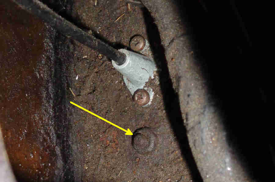 Got both cable and guide very quickly from Sussex Classics, plus new screws for the pedal box as I had three odd ones (they supplied five but there are only four holes), and bottom and cover seals for good measure as I intended to repaint the cover. The guide had a bit of flashing in the cable and screw holes but a moments work with a needle file soon removed that. With the pedal box cover removed again I found I could start the guide screws by hand (slim hands wedged behind the pedal support frame and in the access hole for the 'trumpet'), much easier than I had anticipated. I had screwed them up from the inside of the cabin first to make sure the threads were good and clear. Once started I used the same combination of bit, extensions and UJ to tighten them. Lubricated the new cable by gripping the outer gently in the bench vice, then fed the inner in slowly while I daubed Copper Grease on it, dragging it in to the outer. Once fully in worked the inner back and fore to distribute it, then removed the inner hanging it up to keep it clean. Fitted the outer into the guide, then with clean newspaper over the carpets and seats to avoid getting grease on them and picking up dirt, fed the free end of the inner up through the throttle pedal slot and through the hole in the firewall shelf, the guide, and into the outer.
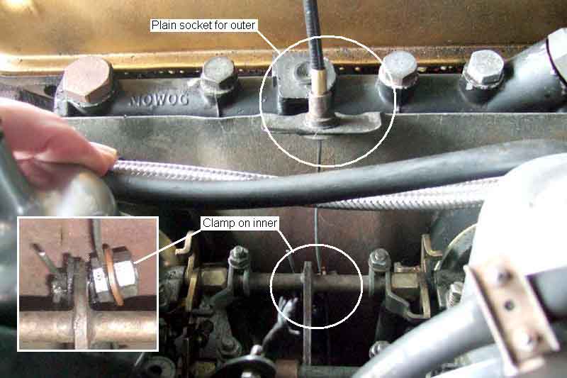 Clamped the free end into the carb linkage. Needed a couple of goes to get the travel right so the pedal hit the stop bracket on the toeboard just as the butterflies hit their stops, then adjusted the pedal back-stop to remove excess play,
but still leave the 12 thou clearance between the finger on the throttle interconnecting spindle and the choke spindle. Much smoother now, no jerking.
Clamped the free end into the carb linkage. Needed a couple of goes to get the travel right so the pedal hit the stop bracket on the toeboard just as the butterflies hit their stops, then adjusted the pedal back-stop to remove excess play,
but still leave the 12 thou clearance between the finger on the throttle interconnecting spindle and the choke spindle. Much smoother now, no jerking.
Stripped and repainted the cover with two coats of Hammerite Smooth, then stuck on the self-adhesive upper seal. Replaced the bottom seal, which was fun. In the end I chose to remove the pedals, then slacken the four bolts holding the pedal frame to the horizontal part of the firewall. I left the two upper bolts to the vertical part, but had enough play to lever the frame upwards gently while I removed the old seal with a flat blade, and slid the new seal into place. Note that it is handed left and right as well as back and fore. Retightened the four bolts, ensuring that the holes in the seal for the cover lined up with those in the firewall, and refitted the pedals, greasing the pivots and clevis pins with copper grease.
Three of the cover screws are easy to fit, but the fourth is in the very narrow gap between the cover and the edge of the wing. I chose to put the screw in the cover, then carefully move the cover into position but raised up a bit so it didn't push the screw out, then got it started using a screwdriver bit handle, 1/4" extension, and appropriate bit. Fitted the other three screws loosely, then tightened all four down. Job done.
Update August 2005: Having done a few hundred miles now the cable seems nearly as sticky and jerky as before. Oh well, at least I know it is sound. Subsequently I removed the 3rd spring from the throttle cable which has improved things. 2022: At some point (no idea when) I put the 3rd spring back and I've not been aware of any problems for a long time.
Four aspects:
- Leaving a little free-play in the cable with the pedal released so the butterflies are held open at idle by the idle screws and not the cable. If the butterflies are left hanging on the cable it can result in an inconsistent idle speed.
- Having enough pedal travel to fully open the butterflies. If the pedal can't fully open the butterflies you are obviously missing out on some performance.
- Making sure that the pedal hits its stop when fully open fractionally before the carbs are fully open so you don't stretch the cable and stress the linkage at the carb.
- Finally adjust the pedal back-stop so that there is just a fraction of free play with the pedal released and the back-stop isn't pushing the pedal down and pulling on the cable.
On HS carbs there should be 12 thou free-play between the finger on the throttle interconnecting shaft and the underside of the choke interconnecting shaft. This is set by positioning the cable inner in the clamp at the carb end. Pedal travel for full carb opening is set by the positioning of the inner in the cable clamp at the carbs. To replace the cable the inner has to be removed from the pedal end, then the new inner removed from its outer, threaded up through the bulkhead and cable guide, then the outer threaded onto the inner being careful not to fray the end.
4-cylinder HIFs are different in that they have a moulded nipple each end of the inner, and the outer has a threaded adjuster where it attaches to the bracket at the carb end to set free-play at idle and full carb opening. The pedal end nipple has to be small enough to pass through the hole in the body and the guide, but the hole in the guide must be small enough to retain the outer. The outer support bracket at the carb end is slotted to facilitate cable replacement there.
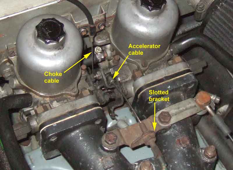 V8 HIFs are different again as there is a moulded nipple at the carb end, plain with a screw clamp at the pedal end giving adjustment, as well as a threaded adjuster on the outer at the carb end, both adjusting free-play and full carb opening.
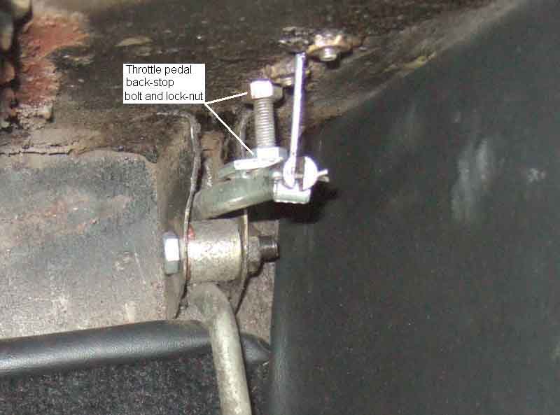 The final aspect is pedal back-stop adjustment that takes up free play in pedal movement, i.e. if you can lift the pedal up when the carbs are on their idle screws. It's important that this adjustment does not start applying a force to the cable by pushing the pedal down. The RHD back-stop screw is adjusted from the footwell and LHD from the heater shelf.
HS set-up
HS components
HIF set-up
HIF enrichment valve
V8 set-up
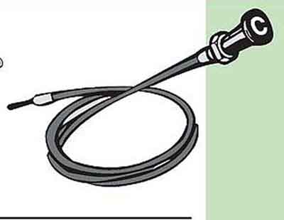 The manual choke was originally a round knob engraved with the letter 'C', changing to one with a 'fan' symbol (representing a shutter-valve) and the word 'LOCK' with an arrow. There were two types - one in hard plastic, and another with a soft rubber moulding holding a disc with the legend and picture. One can imagine this was the later type provided for safety reasons, and is one I can remember on Minis in the 70s. North America got a 'T-handle' choke knob for the 1970 model year, with the word 'CHOKE' as well as 'LOCK' and the arrow, and all (Clausager, but see below) cars got this type from the start of rubber bumpers.
I had assumed that early versions of the 'C' knob at least were 'push-pull' rather than 'twist to lock' based on my (from memory!) 64 Mini, but Dave O'Neil has sent me a scan of a Mk1 handbook which describes it as the 'twist to lock' type. There were two types - BHH526 for North America, Sweden and Germany, and BHH653 for elsewhere. BHH526 has a safety symbol in the Parts catalogue so I suspect that was a soft knob, with the other being hard.
The shutter-valve symbol is not very appropriate and neither is the word 'choke', as they really apply to fixed-jet carbs where mixture enrichment is performed by restricting the air supply, whereas SU carbs perform enrichment by adding fuel to the same air volume.
Which type of knob (hard or soft) was provided when - and even what part number they were is pretty confusing. According to the Parts Catalogue the original UK choke cable changed from BHH653 to BHH651 with HIF carbs (and the new 18V 779/780 engines) for chassis number 332033 (some) to 336650 (all). This cable has the CB round knob, but a longer inner needed for the HIF fittings. It changed again to BHH650 at chassis number 3602301 and the start of rubber bumpers, and the 77 and later catalogue lists it as BHH2064 which suppliers show as the T-handle. However Clausager says the T-handle type was provided on all cars from the start of rubber bumpers, whereas BHH650 as indicated by the catalogue is shown by suppliers as the soft 'shutter' type. Various suppliers list the two 'shutter' types interchangeably, and even the 'hard' shutter type is shown by some for the earliest UK cars - a case of "what we have is the one you want", I'm sure.
September 2019:
The V8 inner is different in that it has a nipple on the end that fits into a slot in a trunnion between the carb choke cams, and the outer is clamped to the air-box to set the correct adjustment. It may also be shorter than the 4-cylinder cable as the carbs are right at the back of the engine compartment. But after that it gets confusing. My 75 has a T-handle and an original brochure shows the same, although the brochure is for the RB models. Clausager shows a 74 with a T-handle but says it probably should have a round knob. The Parts Catalogue only shows one - BHH1121, and Googling that comes up with a round knob from most suppliers, you have to search on BHH1121a for the T-handle. For the 4-cylinder the Parts catalogue lists both - round knob changing to T-handle with the RB, so if the V8 was the same I'd have expected that to have two entries as well. The drivers handbook dated 1976 shows a CB on the front and only the CB front lights, but it's drawings initially show the T-handle ... until it comes to using the choke, then it shows a round knob, and for the remainder of the handbook, even though it shows the V8 binnacle. The only CB V8 brochure I have seen doesn't show the V8 dash, and modern pictures online are no help as they could well have been replaced.
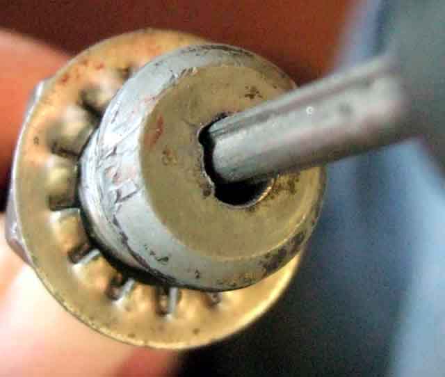 After many years use due to wear the choke control can fail to lock at all,
or in some cases lock but suddenly release at inopportune moments. In some cases,
with the 'twist to lock' type,
this can be due to twisting of the cable inner tending to turn the choke knob in the anti-clockwise (i.e. unlocking) direction,
and so if the inner is released from the carbs and turned in the appropriate direction the twist can be made to aid the locking action rather than oppose it. But mostly it is simply due to wear in the locking mechanism as indicated in the accompanying photos and descriptions (click the thumbnail on the left). Note these only apply to 'twist to lock' types, not friction lock types (which may never have been used on MGBs) although these also eventually suffer from a failure to lock. Putting a twist in the cable so the knob is turned towards the locked position, rather than away from it, will help prevent it becoming unlocked spontaneously.
After many years use due to wear the choke control can fail to lock at all,
or in some cases lock but suddenly release at inopportune moments. In some cases,
with the 'twist to lock' type,
this can be due to twisting of the cable inner tending to turn the choke knob in the anti-clockwise (i.e. unlocking) direction,
and so if the inner is released from the carbs and turned in the appropriate direction the twist can be made to aid the locking action rather than oppose it. But mostly it is simply due to wear in the locking mechanism as indicated in the accompanying photos and descriptions (click the thumbnail on the left). Note these only apply to 'twist to lock' types, not friction lock types (which may never have been used on MGBs) although these also eventually suffer from a failure to lock. Putting a twist in the cable so the knob is turned towards the locked position, rather than away from it, will help prevent it becoming unlocked spontaneously.
On the 'twist to lock' types wear occurs on both the knob shaft and a 'wedge' clipped into the body that attaches to the dash. So by purchasing a new cable it is possible to fit the inner and the 'wedge' from the new cable to the old outer, leaving the run of the outer in position and just undoing the nut on the back of the dash to pull the outer forward to access the wedge, rather than removing the whole thing then having to thread the new cable (inner and outer) through the most advantageous path to get smooth operation. Of course if the old outer is damaged, or is stiff in operation because it is poorly routed, then you will have to remove and replace the whole thing anyway. May be advantageous to pull out the knob, put a spot of grease on the shaft, push it back in till the grease lines up with the wedge and twist it back and fore a few times to distribute it. Then pull the knob in and out a few times wiping the shaft each time to wipe off any excess or you will get grease on the handles of your handbag.
May 2011: John Tait in Australia found his new choke cable failed to lock after just 10 starts. Opening it up he found the locking wedge is made of plastic and had deformed!
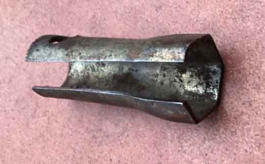 Martin Roberts's tool to aid removal of the cable from the dash.
June 2008:
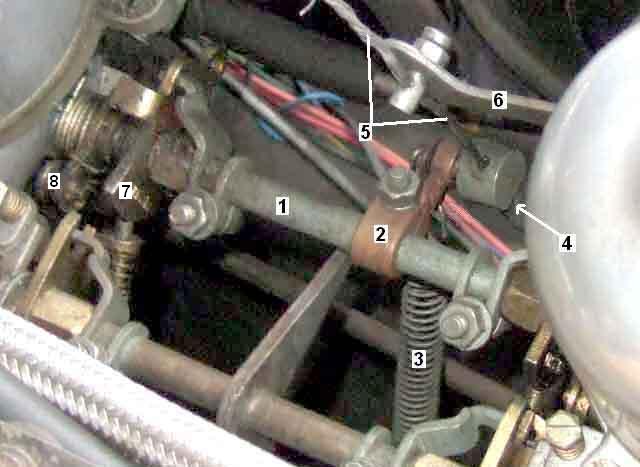 Chrome bumper cars had a curious arrangement - which often causes confusion - at the carb end where the cable inner was fixed, and it was the movement of the outer sliding up and down the inner which lifts the lever on the choke interconnecting shaft. It's quite a neat way of running the cable to avoid clutter above the carbs, but does mean there has to be space for the outer to move around without fouling anything or it can make the choke control stiff. It also makes the cable very easy to adjust - you just slacken the trunnion screw and pull the inner through it to the required position.
September 2018:
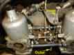 When export models from 1971 (18v engines) and UK cars part way through the 1974 model year gained HIF carbs, they retained the 'upside down' HS choke arrangement even though the throttle cable bracket had provision for a choke cable, which was used to secure the inner.
February 2009:
Rubber bumper cars (and all V8s) the factory used the more conventional arrangement of fixed outer and moving inner using a top-down choke cable. However it's more tricky to adjust - you have to slacken the trunnion screw as before, lift the choke lever up to the required position while pulling the inner down, then tightening the trunnion screw with your third hand!
HS choke components:
 Quite complicated with no less than 11 components. At least they are (nearly) all visible, unlike the HIF carb.
HIF choke set-up:
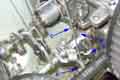 Although the external components of the HIF choke are much simpler than the HS things still need to be assembled and adjusted correctly for the choke to work properly.
In both cases the clamps on the interconnecting shaft need to be positioned quite carefully - these operate the choke cams as the cable is pulled and the shafts rotate, from a finger on the clamps sitting in a hole in its cam. As well as ensuring both carbs operate in unison - rotational positioning on the shafts, they also need to be in the correct position along the shaft. Pressed too tightly against the shaft sockets on the carb they can cause the choke to bind, but positioned too close together the shaft can slide back and fore and one or other clamp may become disconnected from its choke cam.
V8 setup:
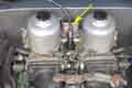 Simpler again, with a nipple on the end of the inner lifting a trunnion that engages directly with the enrichment and fast-idle cams. The only adjustment consists of a simple clamp on the cable outer so you just have to slacken that while pulling the outer up to the required position, then tightening the clamp.
HIF choke valve:
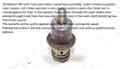 John Maguire in Oz rigged up a bench-test after having problems with a float valve towards the end of a full restoration. As part of that he took the choke valve out and describes its operation. Also shown is an exploded view of the valve components.
Vacuum Port: June 2017
North American 18GK engines in 1971, despite still having HS carbs according to Clausager, then seem to have the distributor connected to a port on the inlet manifold. They had AUD 465 HS carbs, but whether these carbs still had the port but it was capped, or whether there was no port, isn't known.
With the first 18V engines for the 1972 model year all export models gained HIF carbs. North-American models had different carbs to other export markets and did not have the vacuum port, other export markets may have had HIFs with the port, but it's not known whether it was used for vacuum advance.
UK didn't get HIFs until November 1973, and these have the vacuum port on the rear carb as before, but now on the bottom as the butterfly opens the other way. UK carbs were changed to FZX1001 in September 74 with rubber bumpers and this is when the vacuum port was deleted and the source became the inlet manifold. Clausager shows a 1975 with a vacuum connection to the top of the front carb, which would be wrong for an HIF on an MGB, the same picture shows a manifold port capped off so the carb vacuum is almost certainly a user modification. Some people have spoken of drilling the body to add a port to change from manifold vacuum to carb vacuum, even though it makes no difference under normal driving conditions, and if this is what has been done here it has been done incorrectly as the port should be underneath.
From the start of the 1977 model year all export models were to North American spec, including cars for Japan which meant they got LHD cars despite being an RHD country.
V8s always had HIFs with a vacuum port below the throat of the near-side carb.
Whether the port is above or below the throat depends on which way the butterfly pivots as it opens. If the top of the butterfly moves towards the carb, then the port will be at the top, to be presented to manifold vacuum as soon as possible, and this is how it is on HS carbs. If the bottom moves towards the carb then the port will be on the bottom, and this is how it is on HIFs. How the accelerator cable acts on the throttle spindle indicates which way the butterfly moves. On HSs the cable lifts a lever on the manifold side of the spindle, showing that the top of the butterflies will move away from the inlet manifold, and the vacuum port is at the top. But on HIFs the cable lifts the lever on the air-cleaner side of the spindle, showing the bottom of the butterflies moves away from the inlet manifold, so a vacuum port would need to be on the bottom. The V8 pulls a lever that is above the spindle away from the carbs, so again the bottom of the butterflies moves away from the inlet manifold, and hence the vacuum port is on the bottom. The parts catalogue indicates the change from the cable pulling up the inlet manifold side, to pulling up the carb side, occurred at chassis number 332033 in the UK and 25800 elsewhere, which coincides with the change from HS to HIF in each case, indicating that all HIFs - if they had a vacuum port - would have had it underneath. Clausager also shows a 'post-76' car with the vacuum pipe going to the inlet manifold on p67, and on p80 he says the final carbs on UK cars 'possibly for the 77 model year' have much shorter necks to the bellhousings of the suction chambers, but the carbs on p66 and p67 seem to be identical.
Certainly the V8 suffers from fuel trickling down from the port into the vacuum capsule and rotting the vacuum advance diaphragm. 4-cylinder cars may not as the pipe always has to rise to go over the rocker cover. After two V8 failures of the very expensive capsule I fabricated a small separation chamber which I mounted above the carb port, so fuel trickles back to the carb.
Note that if carbs have been removed and refitted check there is some free-play in the throttle and choke spindles that run between the two carbs. The flange nuts may need to be slackened and the carbs repositioned slightly to achieve this. Also the spindle clamps may need to be slackened and the amount of engagement with the cams reduced to give a little fore and aft play.
The engine must be fully warmed up to begin with, and the engine at run 2500rpm for one minute if not driven at normal road speeds immediately before. For the duration of the setting-up process each three minutes the same must be done, to 'clear its throat'.
The basic requirement for good twin SU set-up is that the carbs should be matched - and that means matching springs, needles, jets, air flow and mixture. Springs, needles and jets should always be replaced in pairs. If you have modified the 'breathing' in any way - air cleaners, carbs, combustion chambers, exhaust - you may benefit from a different needle to standard. For example K&N filters may need a richer needle, see SU Needles. While the earlier metal floats can be adjusted to give the same fuel height in the float bowl, it looks like the later plastic ones cannot easily be, except by placing washers between the needle valve and the housing if the fuel level is too high. The float height on HSs is supposed to be such that, with the float chamber lid held upside down, the float should just rest on a 1/8" to 3/16" round bar placed across the middle of the lid parallel to the hinge pin.
Fixed needles on HS carbs must be installed with the shoulder near the top flush with the bottom face of the piston.
Swinging needles (HS or HIF) must be installed with the bottom of the needle carrier, flush with the recess in the piston.
With the earlier fixed needles the jet must be centred so that the piston drops smartly and freely onto the bridge with a metallic click. This test should be done with the jet screwed up to be flush with the bridge, if it drops cleanly here then it will definitely do it when the jet is lowered to its normal running position. If it binds with the jet raised the jet needs to be recentered by slackening the jet bearing nut, pressing the piston down then retightening the jet bearing nut. Recheck, and repeat until the piston drops cleanly. Note that whilst it is easier to do this check with the damper unscrewed, with the damper fitted and oil in the reservoir the piston should still drop smartly, the damper should only retard the upward movement.
Tip: A float valve can sometimes stick in the closed position, particularly if the car is not used for some time. Running the engine will empty that float chamber which will cause poor idle and running. Rapping the top of the (HS) float chamber with the handle of a screwdriver can often free the valve.
Tip: The opposite effect is dirt in the float valve that stops it closing when the float chamber is full and it overflows. Disconnect the fuel pump and run the engine until the float chambers empty and the engine stops. Reconnect the fuel pump and the resulting rush of fuel into the float chambers will usually clear the dirt away. If it happens again immediately either the float could be punctured and full of fuel so it doesn't float, or the valve could be worn. If it happens frequently change the in-line filter (if fitted) or investigate the causes of dirty fuel e.g. internally corroded fuel tank. Check the float height after replacing the float valve, or float.
Tip: Many HIFs, and possibly some HSs, have a 'poppet valve' in the butterfly which opens under conditions of high manifold vacuum i.e. the overrun. This was an emissions measure which simulates opening the throttle slightly until the manifold vacuum drops closer to its normal value at idle. This valve can stick open and cause a high idle, sometimes only during certain circumstances e.g. warming up and be OK the rest of the time. One of my V8 carbs was doing this so I soldered them shut, which needs minimal dismantling to perform. Some recommend replacing the butterfly with the solid item, which has the same effect plus removes a small obstruction from the throat of the carb, but needs much more dismantling and it can be fiddly to get the new butterfly to seat properly in the throat, which leads me onto my next tip.
Tip: A high idle that cannot be brought down to normal by use of the idle screws is not being caused by a vacuum leak. A vacuum leak only lets in air, whereas the engine needs fuel to run. Therefore, if the engine is still running when the idle screws are backed right off, there is some other problem causing one or both butterflies to be partially open. This could be one or more of the following:
- Maladjusted fast idle screws holding the butterfly open, see below for correct adjustment.
- No slack in the throttle cable i.e. the throttle pedal stop is causing the cable to hold the butterflies open. There should be 12 thou (for manuals, 20 thou for automatics) free play between the finger on the throttle interconnecting spindle and the choke spindle. My WSM incorrectly states 0.12" i.e. 120 thou, but it also states 0.3mm which is correct.
- Maladjusted throttle interconnecting clamps and spindle - one carb fully closed is holding the other one slightly open. Go through the full set-up sequence below.
- Butterfly poppet not seating - solder it closed or fit a plain butterfly.
- Butterfly not seating properly - check the carb throat seat is clean and reseat the butterfly.
- Worn throttle spindle and/or bushes - this can cause a vacuum leak as well as allowing mixture to bypass the butterfly.
The main adjustments: Updated March 2023
Note: There are two different types of jet bearing for the HS4 with different threads which affects how far the jet moves with each turn of the mixture adjusting nut - coarse and fine. However everything encountered on an MGB should be the coarse thread, the fine thread only applies to other marques such as the Mini where it has Waxstat temperature-controlled mixture.
- Remove the air filters, slacken the throttle and choke bar clamps, two on each bar, and back off the fast idle screws that bear on the choke cams.
- Screw each jet up (nut under the carb on HS, screw on the side of the body for HIF) until it is flush with the bridge (NOT as high as it will go), then screw it down two full turns to give the basic start-point for the mixture.
- Start and run the engine up to temperature, adjust the idle screws to give a reasonable idle speed.
- Using a tube to listen to the hiss in each intake, or by using a balance meter such as Gunson's, independently adjust each idle screw so you get the same hiss or meter indication in both carbs while still retaining a reasonable idle speed.
- On each carb in turn adjust the jet height to give the correct mixture for your spec:
- On UK cars first registered after 1st August the mixture is set by adjusting the each jet in turn to get the highest idle speed, rechecking back and fore as the balance tube makes them interdependant. You should find that there is a small range of adjustment where nothing happens, beyond that the idle speed starts to fall as the mixture goes rich or weak. From the highest idle point weaken first one then the other until the idle speed just starts to fall, no further. The MOT requires these cars to have a CO reading below 4.5%, but adjusting to achieve that should only be done after the carbs have been fully balanced for air flow and mixture, and then only by adjusting both carbs by the same amount in the same direction.
- Otherwise mixture is set by adjusting for highest idle as above, then fine-tuned by using each piston lifting pin in turn. When a piston is lifted 1/32" it should cause the engine speed to momentarily increase then settle back down - note that the pin itself can be pushed up quite a way before it starts lifting the piston. This isn't easy both from the point of lifting the piston the correct amount as well as hearing changes in the engine note, you may need to 'train your ear' as here, or if still struggling you could try the emissions-controlled HSs method as here. If the speed stays up the mixture is too rich, if the engine speed immediately falls the mixture is too weak. Each carb should be adjusted independently so that it gives the correct, and more importantly the same, results. If you still struggle to detect the momentary rise with the lifting pins then use the method for UK emissions tested cars above i.e. go for the highest idle, about mid-way between where it just starts to drop when weakened and just starts to drop when enriched. After adjusting each carb the other should be rechecked as the balance tube between them makes them interdependent. Adjusting HS jet nuts may well need a special spanner even with the air-cleaners off, even more so with them in-situ. If you have had to adjust one carb noticeably more than the other from the starting point, that indicates there is a problem on one of the carbs, probably the one you had to adjust more. See here for more info on jet height.
- Recheck the air balance again, adjusting idle screws independently as before if required.
- The throttle spindle clamps should be set such that there is a small amount of free play in the throttle cable and interconnecting spindle before the butterflies start to open, and that both butterfly cams start moving at the same time. There is a lever on the throttle spindle that rests on the underside (HS, above on HIF) of the choke spindle when the throttle is closed. Insert a 12 thou (for manuals, 20 for automatics) feeler gauge between the lever and the choke spindle, lightly press down on the part of the clamp that engages with the throttle cam and tighten each nut. Note that my WSM incorrectly states 0.12" i.e. 120 thou, but it also states 0.3mm which is correct. Check afterwards to ensure that the slight play described above exists, that both butterflies start opening at the same instant, and also that there is about 1/32" end-float on the interconnecting spindle. The 12 thou isn't critical but if too small and you need to reduce the idle speed you may not be able to as that reduces the clearance. Likewise if the clearance is too large the throttle pedal will have to be moved more before it starts opening the throttle, and increasing the idle speed increases the clearance.
- Run the engine at 1500 rpm and check that the air balance is still correct. If it is not the throttle spindle clamp(s) will have to be readjusted. Persevere with this, it is important to get both air balance and clearances right - and more important to get them balanced off-idle than at idle for obvious reasons. If you find this difficult to set your throttle spindles/bushes may be worn i.e. can be waggled up and down or from side to side.
- From now on only ever adjust the idle screws by the same amount and in the same direction to obtain the required idle speed. If you start altering them independently you will upset the balance and have to go back several steps.
- The throttle pedal should reach the stop on the floor (or the floor itself for later pedals) just as the butterflies reach fully open but without stretching the cable - the butterflies and cable should not act as the throttle stop. Adjust this with the cable clamp on the throttle spindle (HS) or adjuster on the outer at the carb end (HIF). Take up any free play in the throttle pedal with the screw and lock-nut bolt located near the pedal hinge, make sure there is still the required clearance between the finger on the throttle interconnecting shaft and the choke interconnecting shaft.
- The choke operates in two phases - opening the throttle slightly first (fast-idle), then enriching the mixture. Make sure the choke cable is routed such that it has a clear run when the choke knob is out, otherwise stiff operation can result.
- Adjust the choke interconnecting spindle clamp screws at the carbs such that enrichment commences at the same time on both carbs as the choke is operated i.e. after the fast idle movement has taken place. For HSs the movement of the jets can be observed, for HIFs there are index marks on the enrichment cams and enrichment commences when they are under the middle of the fast-idle screws.
- See here for how the chrome bumper 4-cylinder choke cable attaches at the carb end, it is unusual in that it has a fixed inner and moving outer. There can be quite a lot of movement of the choke spindle lever and fast idle cams before the jets start to move, so set the choke knob at about 1/2" to 5/8" out, then with the cable inner clamp screw slackened pull the inner through the clamp to move the choke lever (for the HIF top-down choke cable lift the choke lever up while keeping the cable under tension) until the jets are just about to move, and tighten the clamp screw. NB: John Twist covers this briefly on the MGA but just says to 'pre-load the cable somewhat'. Unless you pre-set the control first you will be guessing how much cable needs to be pulled through the lever clamp to give half an inch of fast-idle before enrichment starts.
- Adjust the choke cable lever on the interconnecting shaft so that when the choke knob is about 2/3rds out the lever makes an angle of about 90 degrees with the cable, again to avoid stiff operation. You will probably have to go through a couple of iterations of adjustment of the choke lever and the trunnion to get both the angle of the lever and the fast-idle distance of the choke knob satisfactory. Pictures
- Independently adjust the fast idle screws such that as the choke is operated both throttle butterflies start to open at the same time, and gives the correct fast idle speed (e.g. 1000rpm when the engine is hot) when the choke knob is in its maximum 'fast idle' position i.e. just before enrichment starts, and check the air-flow is balanced.
- Check the oil-level in the piston damper. The most sensible way to do this is to unscrew the damper cap lift it up, and press it down again. If you feel the resistance of the oil before the damper cap reaches the dashpot cover you have enough oil. If you try and maintain the oil level at the recommended top-up position of 1/2" above the top of the hollow rod you will be forever topping up which will wear out the damper cap threads and the damper cap will shoot up out of the dashpot cover under hard acceleration. The correct top-up oil is engine oil of whatever grade is correct for your local climatic conditions, e.g. 20W/50 for temperate climates. When you do have to top it up there is no point in filling it to above the top of the hollow rod as any oil above this point is rapidly drawn into the engine, hence the frequent topping-up if you try and maintain it at this level. However see Damper Oil Level
Herb Adler describes using a Colortune. I never got on with them on single-carb engines, so for years never contemplated it for the MGB where you either have to buy two or keep swapping them between pairs of cylinders. Herb describes how it is easy to tell between rich and not rich, less so between just right and slightly either side. Eventually he bought a second one, and even more eventually I first bought one then a second on eBay. I still don't see the colour change between slightly weak and slightly rich any clearer, I can hear the revs change just as easily for coarse adjustment. The only thing I did find with two is that with one carb a bit weaker than the other there is a visible difference in the increased richness when blipping the throttle, but lifting the piston reveals that anyway.
Important: Once the carbs are correctly set up only ever make further adjustments to both carbs by the same amount and in the same direction. Once you start adjusting the carbs independently you will have to go through the above set up to get them balanced again.
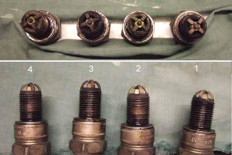 As periodical conformation of the mixture you can check the plug colour. These from the roadster all look pretty good to me, perhaps the back pair are just a smidgen richer. I decided to weaken that carb a tad, and given that it's awkward to turn the HS nuts with the air cleaners on I made a box-spanner, which worked a treat.
July 2014
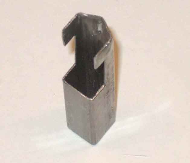 HS carbs are usually adjusted with the air cleaners off, as they restrict access to the adjusting nuts. However if you just want to make a small change to the mixture it's a bit of a palaver to take them off and replace them for something that only takes a second or two. There is a pukka SU spanner, but it's flat, albeit heavily cranked, so I can't really see it being much easier with one of those. So I decided to make a 'box' spanner to do the job, and found an offcut of some 15mm square tubing that I reckoned would suit. I have a spanner which is the correct size for the adjusting nuts, so used that to find a bolt with the same-sized head, to use as a mandrel to form a hex in one end of the square tubing. I used a steel wedge to open out the sides of the square section until I could start to get the head of the bolt in, then hammered it in, and used hammer and vice to make a hex end that was a good fit to the bolt head. The jet has a plastic part below the adjusting nut that carries the enrichment lever that pulls the jet down when the choke is pulled, so I cut one flat off the hex, and for a little way down the tubing, to clear that. Then below the five remaining sides of the hex I cut the edges back half a flat further, to give some 'swing' room to turn the nut one flat at a time. The square section at the lower end gives quite a good grip to turn the nuts - but they shouldn't be stiff anyway, and it works a treat. But if you wanted to you could fit a short tommy-bar through the lower end, or maybe even the handle of a stubby screwdriver, to give a better grip.
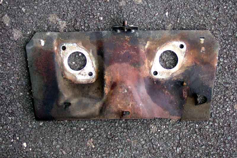 Originally a thin sheet-steel plate with two blocks of asbestos on the back to shield the carb float chambers from exhaust manifold radiation. Asbestos not such a good idea, and current replacements have two pieces of woven material silvered on one side. Can't say I'm impressed with the thickness, time will tell if it's adequate. Bee's has always been pretty manky and I knew almost half of the rear block was missing, so as part of the head conversion to unleaded I decided to treat her to a new one. Spring holes and tabs a bit different to the original - but at least the original ones are present, plus two more tabs in that area. One large tab near the right-hand edge not there, but then it wasn't used so doesn't matter. The new one has two off-set holes near the top edge, for what I can't imagine.
November 2018:
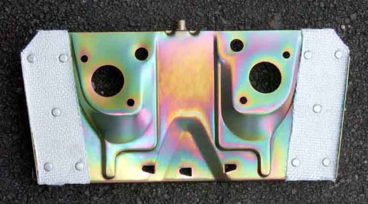 Even though the silvered cloth on the back of the new shield is rather thin compared to the old asbestos - I did wonder if it would be thick enough, despite some very hot weather in the summer this year I had no problems starting or running as usual. Unlike some with summer running problems who seem to think that vaporisation or vapour lock is 'common' and down to the fuel. I'd love to get my hands on one of these.