


The squab is the padded and covered seat back, what you sit on is the base or cushion.
Slats & Spacers September 2016
Mounting Points
Seat Rails
Head Restraints December 1014
Covers and Foams
Seat Webbing/Diaphragm
Seat Belt Guide
Rear Seat Back
Clausager describes many changes of cover, but there were also some significant changes in the frames. 1969 models gained reclining seat backs with a chrome lever on the inside edge of the seat back, and a tilt catch with a black knob on the outside of the seat. Prior to that the backs could be tilted forwards but could be locked in position by a bolted bracket. Other changes at that time were for twin-pole headrests on North American models. 1970 North American models had a single-pole D-shaped head restraint, which became optional and then standard for other markets, with fittings commonised with other BL models. Clausager also writes "The seat frames were altered to cater for modified seat belt mounting points" which is odd as the belts are independent of the seats, but it was possibly necessary for a change to the tunnel belt that allowed single-handed fastening.
October 2020:
 Neil Clark on the MGOC forum reported a problem whereby his passenger seat was at the wrong angle, both the seat base and the back. It turned out that he had an MGC seat that side, MGCs having part of the floor raised to accommodate the torsion-bar front suspension system, and there are other differences. He obtained a Mk1 MGB base, and then had to search for an Mk1 MGB seat back, when he could perhaps have got away with fitting spacers on the front bolts.
Seat Removal & Refitting: July 2013
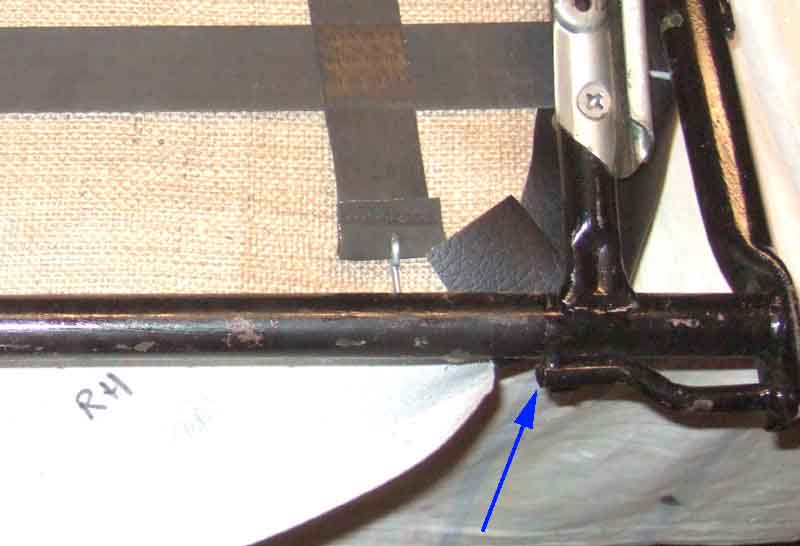
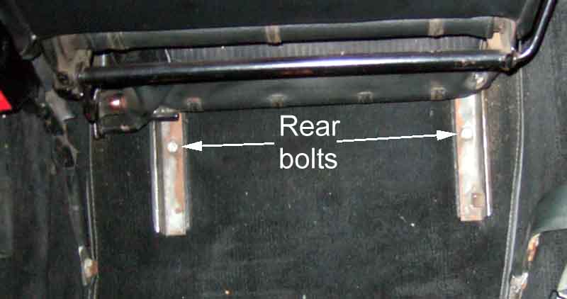 On both my cars sliding the seats fully forwards exposes the rear bolts more than enough to get a socket on a long extension on them, but only once the front bolts have been removed which allows the front of the seat to move across clear of the tunnel. However with the seat fully back the front bolts are covered by the front of the seat frame just enough to prevent a 3/8" wobble extension and socket, or a 1/4" straight extension and socket, or the ratchet on a socket directly from locating on the hex head, so a ratchet ring driver needs to be used. These are worth their weight in gold in the common sizes of 7/16", 1/2" and 9/16", and if you don't have one you will be fiddling with an open ended or a fixed ring for some minutes! But there is another ploy and that is to remove the stop-block at the back of the outboard floor runner, which allows the seat to slide back enough to get a socket wrench on the front bolts.
However there are a couple of things to look out for. The first is the seat-belt buckle, that it isn't preventing the seat from sliding fully forwards, or the seat back ditto - this should be obvious. Less obvious is if the front of the seat is hitting the tunnel as it tapers outwards, before the end-stop is reached, and both these may prevent the rear bolt heads from being exposed. For that reason it is probably best to do as the manuals suggest and remove the front ones first, as that will then allow the front of the seat to swing across a bit as it is pushed forwards, and so clear the tunnel to move fully forwards. Earlier seats and runners could be different, the Mk1 tunnel is narrower, and with non-standard seats you are on your own.
For the runner to floor bolts/screws the Leyland Parts Catalogue specifies SH604101 which translates to GHF102 in modern parlance, and are 1/4" UNF x 1 1/4" fully threaded set-screws. However the MGOC supplied GHF117 to Albert Trayner which are only 3/4" and he couldn't get them to catch the threads. Other suppliers say SH604081/GHF101 which are 1" but would probably be fine. In fact they may be preferable especially at the front where you have to use an open-ended spanner if you don't have a 7/16" ratchet-ring. Note that the spacers sit in holes in the carpet, they do not sit on top of the carpet like the slats do, which would need a longer screw.
The next thing to watch out for when lifting the seat out, and replacing it, is that the tunnel-side floor rail doesn't fall off the seat rail and ding your paintwork, the sill-side runner is retained by the adjuster mechanism. The easiest thing to do is take the loose runner off before lifting the seat out, and only refit it after the seat has been lifted back in, as described here.
Refitting: People seem to get equally exercised about refitting them, saying to put the rear bolts up through the floor first to locate the runners on the threads, before removing first one then the other. If you have the correct slats and large spacers, and if the spacers are in holes in the carpets as they should be and not sitting on top of it, then refitting shouldn't be any problem at all, as the holes in the floor pan should be clearly visible through the runners and large spacers. Maybe a little more difficult with new carpet. The spacers should be held in position by the carpet, so it's just a case of positioning the carpet over the holes, inserting the spacers and fine-positioning them and the carpet, placing the wood slats over the spacers, then dropping the seat in. If you are struggling then a spare bolt (or two) with the head cut off and screwed in a couple of turns from above makes more sense than screwing up from underneath, or simply a cross-head screwdriver to wiggle the carpet, spacer and wood slat into position. The front floor-pan nuts are concealed in the crossmember, so you would only be able to use headless bolts or screwdriver from above anyway. If you get the easy rear ones in first (i.e. the reverse of removal as the manuals suggest), but not fully tightened, then with the seat pushed fully back on the runners the front holes must be at the correct fore and aft distance for the floor pan bolt holes, and it is just a matter of pivoting the front of the seat and runners sideways a bit to locate first the hole in the spacer, then the hole in the floor pan, and removing the stop-block as above will make that easier.
Slats & Spacers: September 2016:
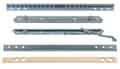 When I restored Bee in 1990/91 as part of completely replacing the interior I also replaced the wooden slats and spacers under the seat runners. The former were rotten but the latter were missing altogether, as I recall. I was perplexed to find the holes in the slats were nowhere near where they needed to be to fit the runners, so had to cut new ones. With considerable care, as the large spacer fits in the holes, which doesn't leave much wood left between there and the sides. Looking at seat components for something else I came across the attached from Moss (also available from other suppliers ...), which includes slats with two sets of holes cut, exactly as I had to do. When I bought mine they must have been for something else, or just plain wrong, as they extend forwards more than an inch beyond the end of the floor runners.
August 2018: As well as some people with longer legs having to position the runners further back on the floor, some have found it necessary to remove the adjustment mechanism altogether and bolt the seat frame directly to the floor to gain a bit more headroom. Some of these have fallen foul of their MOT tester because there is no adjustment on the seat. The regulation gives reason for failure as "fore and aft adjustment mechanism not working as intended" see DVSA MOT manual section 6.2.5 Driver's seat Defect para b i.. If the intention IS that there should be no adjustment, by the seat being bolted directly to the floor, then it is working as intended. The DVSA have apparently said that this failure for a fixed seat gives grounds for appeal, if 'discussion' at the station fails.
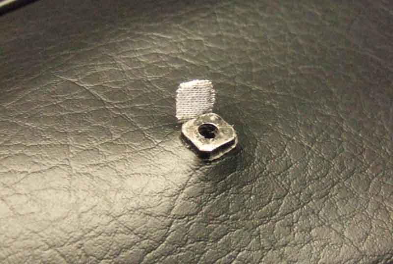
Spacers:
![]() Alloy discs, which go between the rails and floor at each mounting point. Some say their spacers are the same size as their slats, whereas mine are nearly twice as thick. For that reason I chose to cut holes for the spacers in the carpet, and leave the slats sitting on top of the carpet. The bulk of the weight is taken by the spacers, but the slats on top of the carpet spread some of the load and support the runners. With different thicknesses like mine if you put both on top of the carpet the slats wouldn't be doing anything at all, and the runner could sag in the middle. If they are the same thickness, and both placed on top, then as the carpet compresses it could loosen the bolts. But if holes are cut for the spacers then as you tighten the bolts and the runners try to tighten down the slats onto the carpet by the same amount the runners are likely to bow and jam the seat. To get round that some have slits in the carpet so runner, slat and spacer are all on the floor, and a flap of carpet sits on top of the runners. I don't know what original carpets had, but Prestige show holes (image NLA) which look large enough for my spacers.
Alloy discs, which go between the rails and floor at each mounting point. Some say their spacers are the same size as their slats, whereas mine are nearly twice as thick. For that reason I chose to cut holes for the spacers in the carpet, and leave the slats sitting on top of the carpet. The bulk of the weight is taken by the spacers, but the slats on top of the carpet spread some of the load and support the runners. With different thicknesses like mine if you put both on top of the carpet the slats wouldn't be doing anything at all, and the runner could sag in the middle. If they are the same thickness, and both placed on top, then as the carpet compresses it could loosen the bolts. But if holes are cut for the spacers then as you tighten the bolts and the runners try to tighten down the slats onto the carpet by the same amount the runners are likely to bow and jam the seat. To get round that some have slits in the carpet so runner, slat and spacer are all on the floor, and a flap of carpet sits on top of the runners. I don't know what original carpets had, but Prestige show holes (image NLA) which look large enough for my spacers.
The distance between the hole centres for the two rails, i.e. across the width of the car is 12 5/8".
The fore and aft distance between the two holes for each rail should of course be governed by your rails!
The front holes are above the fixed cross-member, about 1" behind the centre-line of the jacking point in two raised pads. These pads are in a flat area between the front and rear flutes, which coincides with the cross-member underneath to give a flat surface for welding. For what ever reason the pads seem to be neither central to the flat area, nor central to the seat mounting points, the holes are displaced rearwards. If you use 1" behind the centre-line of the jacking point you should be OK, there is plenty of fore and aft adjustment of the seat after all!
The distance from the holes to the inner sill panel is 2 5/8" this should be enough to give a small clearance for sill carpets and not rub. It is important this spacing isn't too great or it moves the seat closer to the tunnel which causes two problems: 1) The seat can't be moved as far forward as it will foul the tunnel, and this also has an impact on accessing the rear bolts. 2) Depending in what type of belts you have the seat back may foul the buckle, which will also limit how far the seat can be moved forwards as well as how far the seat-back can be tilted forwards.
The distance from the holes to the tunnel is about 4 1/4" at the rear and 3" at the front, the reduced front measurement being due to the widening tunnel at this point. This occurs on both cars but may be different on 3-synch to my 4-synch cars.
August 2009: There are often questions about what to do about the front holes/nuts when replacing the floor or part of it. I had the same question after welding in a part floor and failing to mark, drill and weld the fronts before welding the floor in! I opted to weld the nut to a 1" strip of metal the width of the nut, cut a slot in the floor slightly more than the thickness of the nut plus strip, then with a bolt in the nut I was able to fiddle the nut through the slot, turn the strip at 90 degrees to the slot, and weld. But after reading other suggestions of a long bolt that goes right through the floor and crossmember (distorting the pan/crossmember if overtightened), or welding a drilled and tapped plate to the top of the floor pan (OK if it replaces the alloy spacer, but doesn't give enough thickness in my view), and how drilling holes in the rear crossmember to allow insertion of a socket to make installation of the gearbox mounting rubbers easier, it suddenly occurred to me that surely the easiest method is to drill such a hole in the front crossmember, plugging it afterwards with a rubber bung (never mentioned in the case of the rear crossmember) to prevent water ingress and corrosion, although that box-section is hardly water-tight anyway, and drainage and air circulation might be beneficial.
 In Bee's seats there is a friction arrangement inside the frame which is supposed to keep the restraint at the desired position. It consists of what looks like a coil spring made out of swarf, in a tube going across behind where the headrest tube goes down, held in place with a wire tie. There is also a spring-clip that locates in a slot in one side of the restraint tube, which hooks under the bottom of the hole in the frame, which only allows you to pull the headrest up so far. Be aware that this has very sharp corners, particularly the part that sticks out of the slot in the tube. Some recovering instructions say to cut a hole in the back of the cover so you can release this if you need to pull the restraint out altogether, which you wouldn't want to do if planning on refitting. But you should be able to peel the cover up from the bottom turning it inside out as you go, with the restraint fully extended, and expose it that way. I had great problems getting the restraints moving in the tubes when I first recovered Bee's seats, to the point on the passenger side that I had to use a hydraulic bottle jack sitting on the floor, with a piece of timber wedged underneath the headrest, and jack it out.
November 2017:
 Vee's are quite different in that there is a plastic rod with a steel bar inside. The head restraint has to be withdrawn before this can be removed, but that was easier in this case, it just needed a hammer and wood drift to tap the clip at the end of the restraint tube up inside the seat frame tube, then it could be pulled out. It is easier to lift the seat out and back in with head restraints removed - if you can. However to do that in a GT means the seat-back has to be reclined, or for non-recliners the whole seat has to be tilted back after the four seat bolts have been removed.
Note that there have been many complaints of replacement seat foams being too 'high', with people resorting to slicing bits off the bottom or drilling holes. I've sat in a GT with them and the wheel was practically brushing my thighs and my head was brushing the roof - most uncomfortable. A pal sat in an RV8 at launch and was looking straight at the top screen frame whereas in his MGB he was comfortably below it. That may mean that RV8s used the 'new' foams, or it could mean that MGBs were like that when new and have all 'aged'.
When planning to replace seat foams and/or covers pay particular attention to the shape of the foams and the covers. Despite reading three sets of instructions, including Lyndsay Porters otherwise excellent 'Guide to Purchase and DIY Restoration of the MGB' and the set that came with the covers, I only discovered that the base foams and covers are handed after I had glued on the first set while restoring Bee in 1990/91.
November 2023:
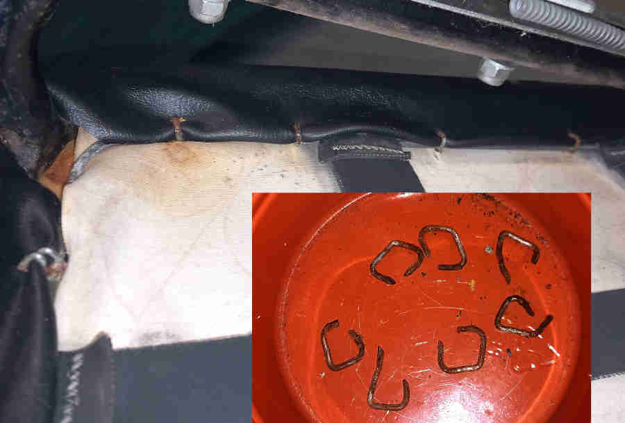 Years ago I read about 'hog rings' being used to secure covers to the frame, always from Americans and had no idea what they are. Both mine and others I have recovered have the edges of the base cover secured to the frame with clips BHA4339 on all four sides, but pal's 78 has small metal rings going through holes in the covers and clamped round the wire of the diaphragm. As he said, they are called 'hog rings' because they are a pig to fit (and to remove), and will use the spring-clips as that part of his covers is black. The benefit of the rings, particularly with light-coloured covers, is that they are invisible with the seat installed whereas the clips are visible from certain angles.
 My seat base frames, foams and covers are all tapered on the inside edge - the front is narrower than the back. Once glued on I did not want to risk damaging my new covers by ripping them off again. Fortunately the difference is not great, and although one can see the mistake if one looks for it, at least it does not stick out like a sore thumb. I've looked at early and late seat frames at Stoneleigh and they all seem to have the same taper, but the early covers seem to be square.
December 2014: This started out as a few tips I discovered along the way when recovering Bee's seats for the second time that aren't in the supplied instructions. As you see there are quite a few!
November 2017: Recovering Vee's is very similar, any differences have been added to the appropriate paragraph. Things like it suddenly struck me that it's easier to leave the loose runner in the car, than try and lift the seat out and replace it still attached, and have to tie it, tape it or hold it in position to prevent it dropping out at the wrong moment. The out-board runner is fine as the adjuster holds it in position. With the bolts removed, fold the seat back forwards then tip the whole seat backwards and you can disengage the runner sideways i.e. without having to slide it out along it's length. Remove the seat still folded, which is probably easiest on the GT at least. Likewise on refitting the seat put the floor runner by the slat, put the folded seat in the cabin, tip it back (if not already done so e.g. GT), and slot the floor runner onto the seat runner. With the seat flat on the floor pull both runners to the rear to expose the fixing holes, insert the bolts leaving them short of tight so the front can move from side to side top help you locate the front holes with the bolts. Slide the seat back on its runners and do the fronts as normal, then forwards again and finally tighten the rears.
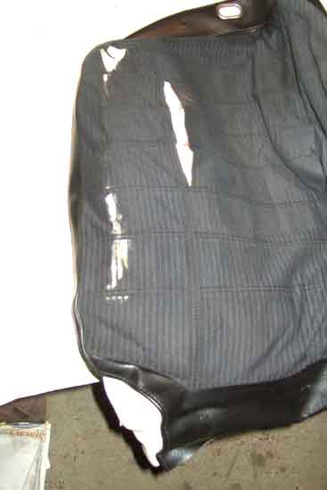 I recovered Bee's seats in 1991 but was disappointed with the quality of the new covers, noticeably flimsy compared to the OEM grey 'deck-chair' covers that she came to me with. Some 25 years later they have gone into holes in various places on the back and wearing thin on the seat. OK, quite a long time, but only 55k miles, whereas what look like OE covers on Vee that were definitely not new and have now done 100k and 20 years with me, and maybe 200k and 40 years overall, are in far better condition. Given the disappointing quality of the previous set I spent some time before deciding which ones to buy this time. Of the people that were able to supply samples only one had the original pattern of fabric and vinyl, but I (and others) have had too many problems with them so won't use them any more. Other than that I was able to see some ready-made covers at Motaclan/Leacy, which looked good to me, so were the ones I settled for, again opting for the black GT cloth over the roadster vinyl for summer comfort. Comparing old and new the old fabric seems to have a woven appearance and quite thin surface texture, and is backed by a very thin layer of foam, whereas the new have a much thicker brushed outer covering with more texture, and a much thicker layer of foam backing. Conveniently the base covers are marked 'right' and 'left' although the included instructions still don't mention the difference, but I'm not likely to get that wrong again! Vee: I used the same supplier again.
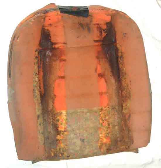 My new 7/16" ratchet ring spanner made removal of the front bolts a doddle - with those out first the seat can be pushed further forwards than normal to expose the rear bolts to a socket. The drivers seat came out easily, but one rear bolt on the passenger side was turning but wouldn't come out. Oddly this had a 10mm head, in the end I used my drill-driver to spin the bolt while I pulled up hard on the seat and it came free ... with a tinkle as what was obviously a free nut under the floor fell onto the ground! I don't remember, but previously I must have used an under-sized bolt and additional nut for some reason. Stripping starts with removing back from seat. There are nuts on the inside of the frame where the back pivots on the base, as well as the bolt being screwed into the base bracket, and 'penny' washers between the two brackets. Took no more than an hour (each seat, although I didn't start the passenger side until the drivers was completed), and that was with carefully peeling back the old covers from the foam where they had been glued to see if I could save the foams again. Ended up usable, as was the card backing. Vee: Unlike Bee's composite foam backs Vee's are one-piece, and in near-perfect condition as is the card backing.
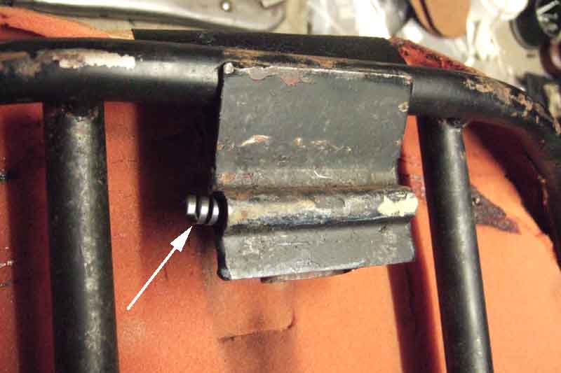
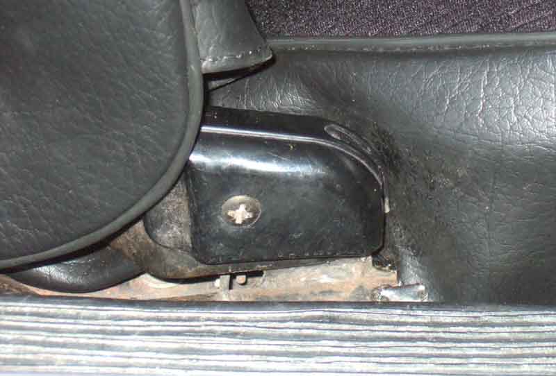 Recently someone somewhere was asking if anyone knew of the availability of pivot covers, as his were broken and they were unavailable from the usual sources. Then while looking for something else on eBay I came across them, recognised them from somewhere else but couldn't remember where. Until I happened to get both cars out and there it was, large as life, on the V8. It attaches with a screw, which goes into a spire clip, and needs a hole in the base bracket, which Bee doesn't have. So sometime between 73 and 75 this cover came in, and Clausager gives it as September 73 at car number 329770, but no reference to them in either of the Parts Catalogues or at any of the usual supplies as far as I can see. They are handed, and need a bit of thought and persuasion to refit. Slide the slotted part over the seat base bracket, then pushing the covers and foams out of the way they can be swung back and down into position. Make sure the spire-clip is in the correct position over the bracket hole first.
As far as removing the head restraints goes Bee's drivers side only slots in loosely, as I used to remove that altogether to fit the tonneau cover that came with the car as that had no pocket (the passenger side was OK as that folded right forwards to be under the cover, the drivers side can only go so far because of the steering wheel). No longer an issue as I have replaced the cover with one with pockets. As previously I couldn't shift the passenger headrest, but was able to peel the cover up and remove the backboard to expose the bottom of the tube, then used a hammer and drift to drive it out. Neither headrest has it's upper 'stop' fitted, but I do still have one of the originals from 25 years ago! With both headrests out the friction device can be removed, which consists of nothing more than what looks like 'coiled swarf'. Only a short piece and some broken bits on the drivers side, more complete but still damaged on the passengers. I shan't be putting those back in as they jam the headrests altogether. However they do need to be raised to act as head restraints, so I may put spacer tubes over the existing tubes to hold them at the right height, as only we two are ever in the car and always in the same seats. Vee: Vee's won't shift so again I pull the cover inside-out up and off the back to expose the friction mechanism. which is quite different to Bee's. Tapping the bottom of the restraint tube with a hammer and wood drift gets them out.
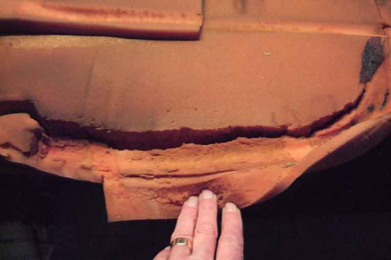
Whilst new-stock back foams are probably OK the base foams are too high and/or too dense. I've sat in a GT with those and the wheel was brushing my thighs and my head was against the sun-roof surround. In the event I reckon both will last another set of covers, saving getting-on for �100. The hessian is like Swiss cheese, so order some off the internet, it prevents the edges of the webbing in particular from cutting into the foam. The backboards are still usable, and the webbing still has plenty of tension after a dozen years or so. Vee: Seat foams, webbing and hessian also in very good condition, but for the cost - �2.49 per square metre, I order new hessian to use a double-layer as I did with Bee. Except for the covers it's all in surprisingly good condition. Given the amount of what looked like decomposing foam dust that had been gathering on the carpet under the seats, I expected them to be in very poor condition. Quite possibly recovered with new foams, card and hessian before my time, but the only thing that looks like it could be a date code on the foams has what would be an '04' year number, and I've had her since 1995!
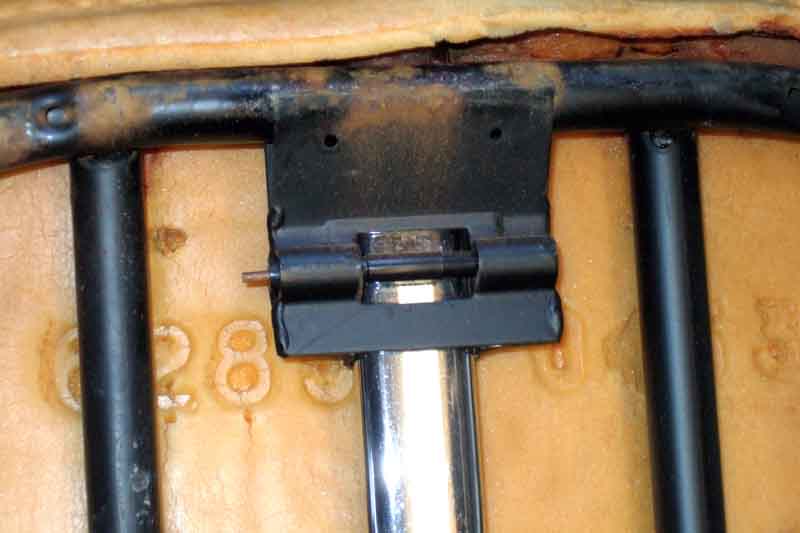
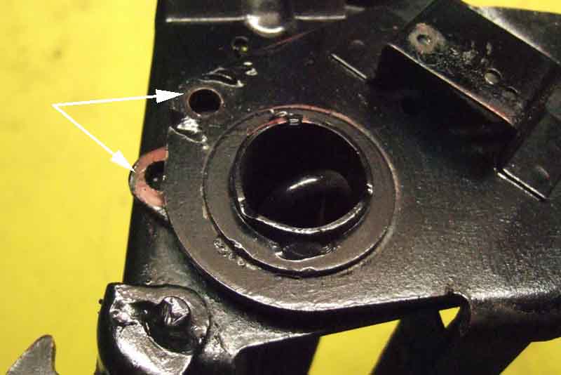 Something I've been wanting to do for 25 years was have a look at Bee's drivers reclining mechanism. When refitting the seats after the previous recovering a metal pin fell out, which looked like it had been welded somewhere. After that, I found that if I leaned back hard to get something out of a trouser pocket the seat would shoot backwards - so that pin was probably something to do with the recliner. I kept it, but it's got mislaid somewhere along the way. Examining the frame carefully there is another welded pin that guides the recliner handle mechanism - at least it should be welded, this was quite loose which allowed additional movement of the handle mechanism. I wonder if that is the problem and the other pin is a red-herring. Then where the seat back pivots during reclining I could see a hole with some weld around it where something had obviously broken away - that must be it. There is a plate underneath that with another hole, and when the two holes are co-located with a pin it locks the teeth of the reclining mechanism together until the reclining handle is operated. Without that pin the seat back is 'free' (against considerable spring pressure it is true) to move without use of the reclining handle and disengage the teeth of the reclining mechanism, which allows the seat to shoot backwards. I find a bolt with a plain shank that just fits the holes, cut it to length, and weld it in place, as well as welding up the loose guide pin. I could put the seat back in the car and lean back hard to test it, but that's a bit of a faff, so I wedge the corner under the full length ramps, which have the weight of Bee on them, and push hard on the back, and it shows no signs of moving. I'll leave it at that, if it still collapses I wouldn't really know how to fix it, so I'll just live with it and not lean back hard!
 The irony is that when I had fitted the new cover I could clearly see my repair to the pivot, so could have reattached the original pin - if I had known where it came from at the time - when it fell out all those years ago!
 The back foams on the drivers side have torn a bit where they rest against the outer frame uprights, so I lace three strips of gaffer tape round the outer uprights and behind the rear uprights to give it a bit more support. The backboard goes back on with two screws and large washers at the bottom, and a few pieces of gaffer tape to the frame sides and top. Sprayed glue round the frame and corresponding parts of the foam. There is a rectangle of vinyl that I have left glued to the top of the back foam around the headrest hole, so I position that over the hole in the frame. Another 'supposed to' is to glue polyethylene over the shoulders of the foam to help the cover slide down. I did that last time, but never liked the crinkling sound it made ever after. Other instructions say to put a plastic bag over the foam, then rip it out after pulling the cover fully down. That is preferable, but I decided to glue a strip of cling film over the shoulders and down the sides, which allowed the cover to slide fully on quite easily, and doesn't make a noise when using the seat. Vee: No such problems with the foams, and the back-boards are in good condition, but I'll probably do the same.
 After a trial fit I pulled it back up again to fit the half-moon cards (provided with this set, unlike the previous where I had to make my own) into the pockets at the bottom of the sides. It's worth spending a little time teasing the stitched edges inside the pockets onto the inside face of the card, so the cards are fully seated in the pockets and the outside face of the vinyl has a nice flat appearance. Glue them in place as they can get dislodged while fitting the cover to the seat and the stitching ends up on the wrong side again, although this needs doing before the cover is fitted to the seat. All work so far has been done with the back re-attached to the base as that holds the back upright while pulling the cover down. Vee: Vee's half-moon cards are not ideal, one is OK, but the other had been glued into the pocket which pulled some layers off on removal, leaving it a bit thin and floppy. However the previous set came with new cards so hopefully these have as well.
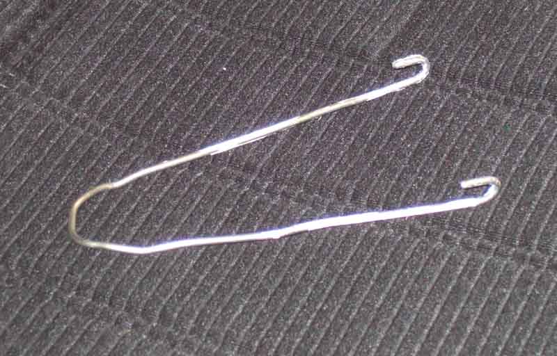 Next the ears need to be screwed to the brackets on the seat back, as this helps to keep the cover tugged fully down when you come to clip the vinyl to the bottom of the seat back. Easiest done with the back removed from the base. Finding the existing hole for in the brackets is tricky. You could cut the head off a self-tapper, screw it into the bracket point outwards, then tap the outside face of the ears with a hammer so that the point of the self-tapper pierces the car and the vinyl, then remove the self-tapper and fit the screw and cup-washer. I opted to make a 'puller' out of bent coat hanger wire, which hooked over the straight edge of the card in the ears, held in position with a bar wedged across the frame to keep the ears tugged down, then drilled through from the outside. You only need to be approximately in the right area as the bracket is plenty big enough. I did this the last time, and there were already two holes there then so whoever had fitted the covers that Bee came to me with had obviously done the same thing. There are now four holes, but that doesn't matter as they can't be seen of course.
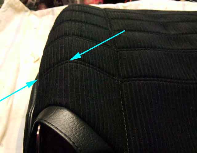 As pulled on the cover will take the shortest route across the seat back above the face of the central section of the foam between the side bolsters, but it needs to be glued down with the vertical stitching on the cover positioned in the angle between the central foam section and the side bolsters. The outer corners of the bolsters need to be as near to the join between the cloth face and the vinyl sides of the cover as they can be, but left to their own devices they will be a couple of inches away under the cloth face. Push down on the face of the cover while simultaneously pushing the edge of the foam towards the join, and the stitching will reach down to the angle between the central and side bolster sections of the foam more easily. After practising that with no glue, spray adhesive into the angle between the foam back and side bolsters, and onto the vertical stitching on the back of the cover that needs to fit into that angle. A couple of applications is probably best as both surfaces are absorbent, then repeat the manipulation of the foam towards the join between cover face and sides, before pressing the vertical stitching down into the angle between foam back and side bolster, while trying not to stick yourself to either part. With both sides done press down with the forearms up the line of stitching until the glue takes.
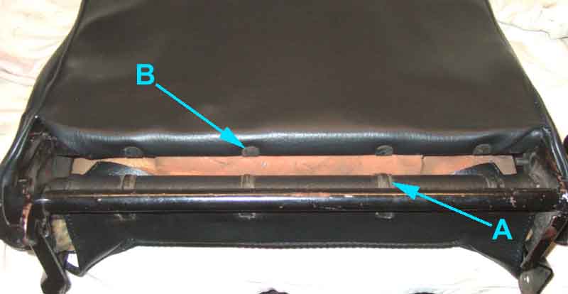 Apply adhesive to the inside of lower back of the cover and the 'angle iron' that this piece attaches to with the flat clips. Wrap the vinyl round the angle iron, leaving a triangle folded back at each side where it is attached to the vinyl sides, pushing the horizontal edge behind the foam, and fit the flat clips. This is easiest done before tackling the vinyl strip at the bottom of the face of the seat cover, that goes round the large tube, attached with four round clips. Note that the clips you took off the tube will probably be larger than the ones taken off the base frame having opened up a bit, so if you haven't kept these separate pick the four biggest to refit to the tube. These have to be lifted over the tube, simply pushing them on will probably tear the vinyl from the 'teeth' on the clip that hold it in place.
 Finally tap with a hammer on the vinyl where it lies against the edges of the square bar for the reclining handle, to cut out a neat square of vinyl, and replace the handle.
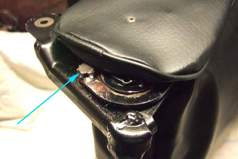
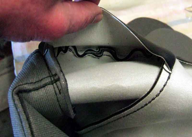
For years the Navigator has been complaining about a rattle somewhere behind her, and whilst I could just about hear it myself when she was in the car I couldn't when I was on my own. The toolbox lives in the boot immediately behind the bulkhead her side, but despite removing that and everything else it was still there. But when manoeuvring her seat back on the bench during recovering (but not mine) I heard a rattle, which on investigation turned out to be the recliner folded torsion-bar spring inside the large tube at the bottom of the seat back. I stuffed some strips of hessian in there, time will tell if that has done the trick (it didn't).
The base is relatively easy. I had a metre of hessian and the width was enough for a double thickness on both seats. Apply glue to the foam and one side of one sheet first, then stick that down, then more glue on the top of that piece and the second piece, and stick that down.
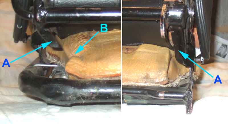 The instructions say to make identical marks on the base foam and cover at the front, but I found with these base foams with the raised sides and flat front it only goes on in the correct place. If you have the humped front foams and apply glue to the hump you probably will need to mark foam and cover first to get it aligned. What is very important in all cases where the seat back can tilt forwards is to get the rear of the foam, where it goes under the seat back, in the correct position. It is tapered in that area between the pivot brackets because part of the back frame drops down either side of the foam and cover there. Get it off-centre, and the back frame will come down onto your new cover and foam, crushing it, and perhaps eventually ripping it. Re-attach the back to the base with just a couple of turns of each bolt, drop the foam on the base and position it between the relevant parts of the back frame. I used pieces of tape on the base rear tube to mark the position. Check that the angles between the central flat parts and the side bolsters of the seat foam line up with the vertical stitching on the back cover and adjust if necessary. With the seat back removed again glue the foam and hessian to the front and side rails of the base using your marks. Trial-fit the cover to check all is well, apply glue to the central section of both foam and cover, and fit the cover pulling it down at the front and the rear before pressing the central section down to bond. The stitching should lie in the angle between the flat part and the side bolsters, which should mean it will line up with the vertical stitching on the seat back.
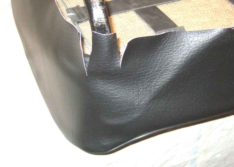 The instructions talk about cutting the vinyl sides by the pivot brackets, but they also need to be cut either side of the uprights at the front that go down to the runners. Cut at the front down the inner side of these uprights, and again on the sides in line with the rear edge, and fold the vinyl back on itself, then you can neatly glue and clip the front and sides to the frame. At the pivot brackets cut in line with the front edge of the bracket and tuck the rear part of the vinyl behind the brackets. I applied glue to the sides of the foam at its narrower section behind this bracket to keep the cover from getting trapped under the metalwork of the seat back as it is folded back. Tuck the spare vinyl between the webbing and hessian.
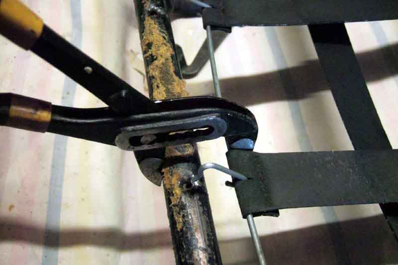
 Also necessary is to cut the rear vinyl strip in line with the end of the bar that is welded to the rear tube, that the tipping seat back latches behind. If you try to wrap the vinyl round that it won't lie flat and can't be clipped there anyway. That allows the vinyl to be neatly glued and clipped to the main tube, with the surplus again being tucked between the webbing and hessian.
And that is basically it. Reattach the back to the base, with penny washers between the two brackets and the smaller washers under the bolt heads. As soon as the bolt thread starts coming out of the inner bracket, position the lock-nut on the inner face so that as you screw the bolt into the bracket it screws into the nut at the same time, much easier than trying to fit the nut afterwards. Tighten the bolt just short of nipping the small washer up, then hold the bolt while you tighten the lock-nut.
 Finally refit to the car,
 fitting the lower runners to the upper first. The adjuster should hold the sill-side runner in safely, but you will need a tie of some kind round the tunnel side runner and frame member to stop that sliding off while lifting the seat into the car, removing it once the bolts are in but before tightening them. Vee: As mentioned above by removing the loose runner while the seat is still in the car, and not reattaching it until the seat is back in, avoids it dropping off when lifting it in or our, or having to tie/tape/hold it. It's also easier to leave the head restraints off until the seat is back in the car in a GT. However I then discovered that it wouldn't go in with the seat back upright as the roof was too close, nor with the seat-back tipped forwards as the screen was in the way! Fortunately, with reclining seats, they can be fitted with the seat-back reclined. If you chose to leave them out on non-reclining seats you will probably have to tip the whole seat backwards before inserting any bolts.
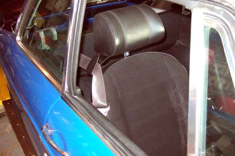 But after using Vee for a couple of days, I'm finding that with the new covers the belts are slipping off the shoulders of the seats when getting in and out, instead of staying there and being easy to grab hold of to fasten before driving off. They wouldn't stay there at all on Bee so I made some retainers/guides some time ago, so make another pair for Vee.
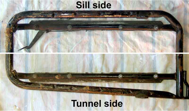
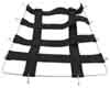 Updated July 2022: Webbing uses two more hooks than the diaphragm - four down each side plus two front and two more at the back. The diaphragm only uses two each side plus two in the front corners, and again two at the front and two at the back. Early frames don't have the holes aft of the seat back mounting point and are also missing one each side further forwards, which would have to be drilled to use the webbing. Later frames seem to have holes for both types which means you can use whichever you prefer.
I changed the webbing on both seats when I restored the roadster in 1990/91 and the drivers side again about 10 years later. A few years later sitting in the passenger side I realised that side needed doing as well. The webbing hadn't broken as before, but had lost its tension. As such it came off relatively easily, but I remember some difficulty in fitting new webbing on both previous occasions, getting enough leverage to stretch the webbing enough to get the 2nd hooks into the frame, and doing it on my own. Previously I had used a length of timber and some rope, levering the timber against the frame with one hand, to pull on the rope looped through the main wire frame of the webbing, using one foot to hold the seat steady on the ground, and the spare hand to press the clip into the frame. It was a bit of a fiddle tying and untying the rope each time and getting the right length of loop, this time I decided to try something different, and it was much easier.
Remove the seat from the car by undoing the front bolts first (with a 7/16" ratchet ring). This then allows the seat to be moved right forward so you can use a socket ratchet on the rear bolts, which is much quicker. If you undo the rears first you will probably have to use a spanner on all four. When lifting the seat out of the car watch the tunnel-side 'fixed' rail doesn't fall off and hit your bodywork, it is now only hanging on the sliding lip. As recounted here with the bolts out tip the whole seat back and detach the inner floor runner, and don't replace it until the seat is back in the car. The outer rail should be held securely by the seat-locking mechanism. Remove all the spring clips holding the seat cover onto the frame and peel the cover back as normal, and remove the old webbing. Don't chuck it yet, one of the hooks on the new webbing was missing when I received it, and another pinged off somewhere, the old ones were fine as replacements.
December 2014:
 Subsequently on webbing I used a pair of channel lock pliers to pull the wire that goes through the hooks towards the frame, then another pair of pliers to manoeuvre the hook out of (or back in to) the frame. Do the front edge first then the rear (which has no wire through the hooks) can by unhooked by hand. Much easier than the diaphragm or the previous rope and lever method with webbing.
Take this opportunity to clean and grease the sliding parts of the rails, making sure they are straight and flat. Also replace the wooden slats and alloy spacers if they are missing or (in the case of the slats) rotten. If the seat lock wasn't working properly, now is the time to tweak that as well.
Refitting the seat is the reverse of removal, again watching the inner rail doesn't fall off not attaching the inner floor runner to the seat runner until the seat is back in the car, and tipped right back. I've not found it difficult to locate the bolts (rears first as they are easier to see) by wiggling things round until they line up, but some recommend putting bolts up through the rear holes first (you can't get at the fronts) as locating pins. With the back bolts in just short of tight, and the seat pushed right back on the runners, you only have to wiggle the front of the seat from side to side a bit to locate the first front hole, then the second should be in the correct position.