


and hazard flashers
Hazard warning schematics
Indicators
Hazards
The indicator/turn switch Added August 2008
Where is the flasher unit?
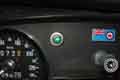
Dash tell-tales
Fault diagnosis
Indicator Flasher Replacement May 2016
LED flashers
Adding hazards to earlier cars October 2010
A louder audible warning
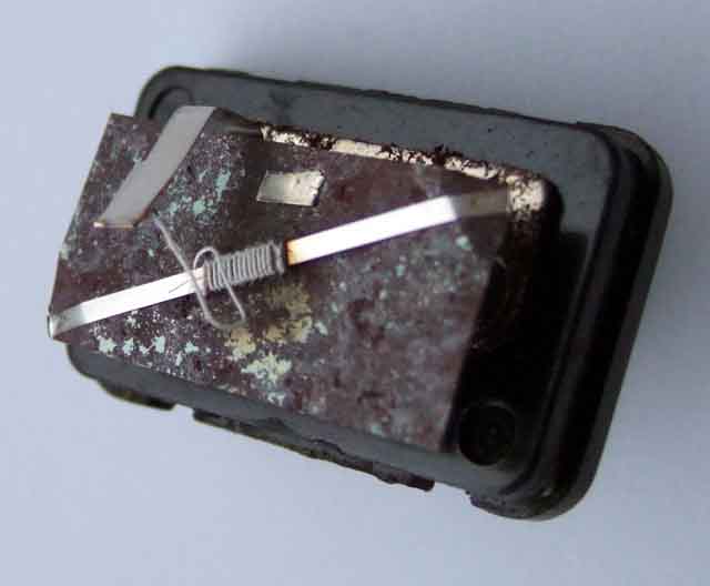
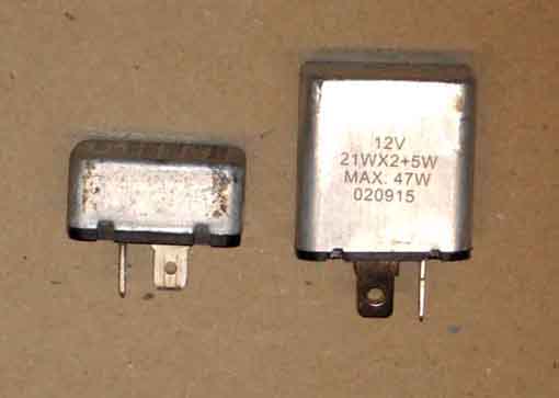
the innards of each flasher unit
Indicator and hazard flasher units are not 'relays' as often stated, if anything they are 'switches', but that would cause confusion with the manual switches, hence 'units'. A relay receives an input voltage from one source which powers an electro-magnet to close a contact which completes a separate electrical circuit. It isolates the two circuits so that the electrical characteristics of one can't damage the other. By contrast an indicator or hazard flasher unit takes the input voltage and extends it through to the output i.e. it is simply switching the input voltage on and off.
Indicators: For Mk2 and later go here, but for Mk1 read on - it's complicated, as complicated as Mk2 but in different ways.
Another difference to the later 2-terminal units is how they respond to a failure of a bulb at the corner of the car. From brief exposure to one of these units with one bulb not working the other bulb only makes a very brief flash, barely visible to other road users.
If that wasn't enough there are at least two types of this flasher unit - one for MGBs and one for Triumph TR4 and earlier, and the difference is in how the tell-tale is operated. Helping a pal with the indicators on his TR4 he had bought what he thought was the correct flasher unit ... but the tell-tale was on all the time with the ignition, albeit flashing when the indicators were being used. From what I knew about the Mk1 MGB system I realised that what he had was an MGB unit, which has the additional contacts on the indicator switch so the tell-tale is off when they are not being used. The TR4 only has one tell-tale for both sides, and no extra contacts on the indicator switch, so it needs a flasher unit where the tell-tale contact is not live until the unit starts flashing. Paradoxically it wouldn't matter if the TR4 and earlier unit was used on an MGB, so the question has to be why the MGB had a different one (the MGA apparently had two different systems, one the same as the Triumph and the 1500 which is completely different as it involves flashing the brake lights).
Current replacements can be stocked as GFU101, GFU2101, GFU103, GFU2103, SFB105, FL5, FL54, C16729, 35002, 35003, 35010, 35028, 35028A, RTC3560, UD1511 and probably others! Some of them are for Triumph but will work equally well in the MGB (unlike the other way round). Some Triumph sources report similar problems to the Lucas SFB115 two-pin flasher unit for Mk2 including being a hazard flasher and not an indicator flasher.
Mk2: A simpler system with only Lucar/spade two terminals on an 8FL flasher unit - 12v to B (green) and L (light-green/brown) to the indicator switch, and no extra contacts on that switch. The two dash-tell-tales are simply wired in parallel with the bulbs at the corners of the car - one per side, so come on and go off with the corners. These units have the safety feature that as soon as you operate the indicator switch both the corners that side (and the dash tell-tale) light up, and after a pause start flashing off-on-off-on. However there are a number of 8FL units and some are not correct for the MGB. There is a 'type' number on the original Lucas can which can be 36, 41, 50 and maybe others and this relates to the current they are designed to work with which is dependant on the number of bulbs and their wattage.
A second safety feature is that if one corner fails the other corner and the tell-tale will glow steadily instead of flashing, which is a warning to the driver that they may need to start using hand-signals.
A drawback of this system is that the flasher unit is very sensitive to voltage and current, and with low voltage or increasing resistance from ageing connections and bulbs the flash rate gets slower and slower as well as reducing the brightness of the bulbs, and this is where some have changed to using three-pin electronic flasher units. Many of these (but not all ...) have the same safety features of lighting up straight away and indicating when a corner has failed, except that in the latter case with one corner not working the other corner and the dash tell-tale will flash at double speed. Being electronic they don't suffer from slowing down with falling voltage or increasing resistance issue and give a much more consistent flash rate, BUT ... bulbs that are dim from poor connections will remain dim. It's a significant exercise to investigate that, and there can be very many small extra resistances throughout the circuit to find and fix, although fixing the greatest resistances first will have the greatest effect.
Current stock replacements are the aforementioned suspect SFB115 as well as SFB114, GFU125, GFU2125, 8FL, 35049. Note some of these may be cylindrical, the can won't fit the original rectangular clip but may come with its own clip. Also that rectangular ones may be double-height but they fit the original clip. Confirm that the packaging or can states '48W' or '50W', and/or '2 x 21W' (may also include '+6w +2w') and NOT '12A', '96W' or '4 x 21W', however even then some types will flash slower than they should. When fitted immediately test and confirm that as soon as you operate the indicator switch the lamps light up, then after a short pause start to flash - may well need the engine to be running to flash at an acceptable rate, also that with one bulb disconnected the flash rate changes markedly.
That leaves LED bulbs which are whole different world of pain in the indicator flasher unit department.
Supplementary hazard light
These operate differently to indicator flashers and are a different construction internally. For a start when you first turn on the hazard switch nothing happens, then they start flashing on-off-on-off. Secondly they are capable of flashing anything from one to four main bulbs (plus side indicators and tell-tales) if for example the vehicle has been in an accident and one or more corners are damaged. Secondly they are relatively insensitive to falling voltage as they may be left operating for some time without the engine running, and flash at a relatively consistent rate. Two-pin devices (like the Mk2 indicator flasher) - 12v to B (brown) and L (light-green/brown) to the hazard switch which links the two sides and connects the flasher unit to them. The flasher switch has two more contacts that are normally closed with the hazards off and these feed fused ignition power (green) to the indicator flasher unit. These contacts disconnect that when the hazards are operated, otherwise if the indicator switch was left operated power from the hazard flasher to the corners of the car could feed back through the indicator switch and the indicator flasher onto the green and white circuits, and hence power the fuel pump and the ignition even with the ignition key in your hand - an obvious safety hazard in the event of damaged fuel lines.
Unfortunately having two spade terminals like the Mk2 indicator flasher unit they can be substituted for each other in error. With a hazard flasher in place of an indicator flasher things will appear to work, but there will be a delay in the corners lighting up when the indicator switch is operated, and there will be no indication of bulb failure. The other way round is more obvious as with an indicator flasher trying to light all four corners there is only the briefest of flash lighting them before they go off again.
With LED bulbs at the corners the standard hazard flasher may work if there is are incandescent bulbs in the tell-tale, but probably not if they are LEDs as well.
Hazard lights were standard on North American spec cars from the start of Mk1 production in 1967, on all V8s, and non-North American 4-cylinder cars from the start of the 1974 model year i.e. the last chrome bumper cars according to the list of detailed changes in Clausager ... or is it? He says in the text that they were also available as an optional extra on home market before that, but that the information available is 'conflicting', and it is. He says the 1973/74 GT brochure for home market cars quotes them as an optional extra, but no mention at all in the 1974 roadster brochure. '1973/74' could be taken to mean both 1973 and 1974 models, but could also be the model that was built during the second part of 1973 and the first part of 1974 which would be the 1974 model built from August 73 at chassis number 328101 (roadster) and 328801 (GT) to September 74 at chassis number 360301 (roadster and 361101 (GT). Elsewhere he says they were 'probably' fitted to all home market cars from the start of the 1974 model year. The Leyland schematics show it for 1974 models but not for 1973 models, in neither case as an option. The Parts Catalogue shows hazard switch BHA5267 being used for RHD chassis number HD5-328801 which is specifically GTs from the start of the 1974 model year, but it doesn't indicate it is an option unlike for fog and spot light switches. Flasher unit ATJ8880 is specified for chassis number 328101 (roadster) and 328801 (GT) i.e. all 1974 model cars and again no indication of being optional. The only clear thing is that all RB cars had them. It may be that when the 1974 model brochures were being produced it got into the GT one but not the roadster one, and by the time it came to build the cars they had decided to fit them to both roadster and GT anyway (why would they fit it to one but not the other?). Who knows, other than looking at actual cars of the period, but even that is fraught.
Brian Wall has said his November 72-built GT has them i.e. a 1973 model built between August 72 and August 73, which raises the possibility that they were an option in 1973. But that could be a mod by a previous owner, possibly with a rewire, it looks like that was the only electrical change between 1973 and 1974 models. If it had been an option the later harness could have been installed on the line as required, or maybe it was on all of them and the switch and flasher unit not provided. In which case there would need to be a dummy 'switch' on the connector to link the two green wires together or the indicators wouldn't work, in which case to add hazards would just be a case of adding the switch and flasher unit to the connections. The option could also have been a sub-harness added to the earlier standard harness, which is what I did.
Adding hazard flashers is not simply a case of tapping into a 12v supply and the wiring to the corners of the car which is easily done. The hazard switch when on has to interrupt the power to the indicator flasher unit for safety reasons. Feasible with a sub-harness as it would be a case of simply removing the 12v feed from the indicator flasher, connecting that to the sub-harness, then connecting another wire in the sub-harness back on the indicator flasher. But if the main harness had provision for optional hazards there would need to be an link (insulated from coming into contact with anything else as it would be part of a bunch of wires not attached to anything i.e. flapping around) between the two green wires going to the switch, removed when the switch was provided.
May 2019: A puzzling problem for Steve Henson-Webb on the MGOC forum. When using his indicators the dash tell-tales worked, but when using the hazards they didn't. The appropriate corners of the car flashed when they should. Unfortunately he didn't mention until later that when using the indicators both tell-tales were flashing, but dimmer than usual, which made things much easier to understand. The problem was the earth wire to both tell-tales had become detached. That meant that when using the indicators the tell-tales were effectively in series to earth via the indicator bulbs on the side of the car that wasn't flashing, so both flash, albeit dimly as each has only 6v instead of 12v. When the hazards are on both tell-tales have 12v on their 'live' sides, but no earths on the other, so neither flashed. The puzzling thing is that it was a 1974 CB, but on Mk2 tin-dash cars (e.g. my 73) there is no earth wire for the indicator tell-tales that I'm aware of, the bulb holder picks that up from the bracket they are pushed in to, which is attached to the back of the dash. He says it happened after fitting a radio, maybe that interrupted the dash earthing somehow, but seems unlikely. Mk1 cars (which didn't have hazards from the factory of course) did use 2-wire indicator bulb-holders as the 12v supply was switched from the flasher unit and the earth supply came from the indicator switch. North American Mk2 with the padded dash, all V8s and all RB cars also have 2-wire indicator bulb-holders as they are mounted in plastic panels so need a wired earth.
The indicators are powered from one of two green (fused ignition) circuits - originally the one in the fusebox. But sometime in 1978 when the ignition relay circuit on RHD cars was modified to add a second in-line fuse between brown/white and green wires under the fusebox, the indicators (and tach, heater fan and GT GRW) were powered from one of these - the one with the thinner wires, the other with thick wires being for the cooling fan. For more information see the ignition schematics. On cars equipped with hazard flashers the green circuit goes via the hazard flasher switch to be connected when the hazards are off, and disconnected when they are on.
By all accounts indicators are the bane of an LBC-ers life. But like all things, they worked when it came out of the factory. If it doesn't work now then there must be a reason (or two or three), so it can be found and fixed.
But first - know the difference between indicator/turn flasher units (they are not relays, strictly speaking they are thermo-switches) and hazard flasher units:
- With indicator flasher units as soon as you operate the switch the lamps should light up, and after a short pause they should start flashing off-on-off-on.
- With hazard flasher units as soon as you operate the switch nothing happens for a short period, then they should start flashing on-off-on-off.
If you substitute an indicator flasher for a hazard flasher it will appear to click at the correct rate but will only send power to the bulbs very briefly, not long enough to fully light them, and may burn-out quickly as they are only designed to flash two 21w bulbs (plus a 5w wing repeater on the 2-pin types) not four. But if you substitute a hazard flasher for a 2-pin indicator flasher it will at first seem to work correctly, unless you notice the sequence (as above) is incorrect. This is a safety hazard, as it delays the lights coming on and hence the warning to road users. So many people these days seem to operate the indicators at the same time as they turn the wheel that the rest of us need all the warning we can get!
There are also 'universal' or 'heavy duty' flasher units that although they may have the correct sequence for indicators i.e. they come on as soon as you operate the switch, don't have the built-in 'bulb failure warning' of the originals. Really when fitting an alternative flasher unit you need to disconnect one corner and confirm that you still get this warning. On original MGB types this warning is that flashing stops altogether, and only one external bulb will be lit. On modern electronic units the remaining bulb should flash at double-speed.
To complicate matter even further there is another type of after-market indicator flasher unit intended for use with after-market LED bulbs, more on those here.
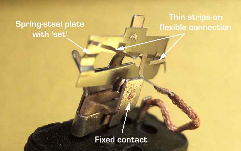 Originally the MGB used a cylindrical 3-pin flasher unit (GFU103, Lucas FL5), but this is not the same as modern electronic 3-pin flashers. On the originals the third pin is used to flash the dash repeaters via additional contacts in the indicator switch, whereas on electronic units the third pin is connected to earth. Mk2 MGBs used a rectangular 2-pin indicator flasher unit (SFB115 (was GFU107), Lucas 8FL) as the dash repeaters are now connected to the wiring going out to the corners of the car. Both the original MGB types are 'thermal' type flashers and the following information is from Steve Blakeway who was an employee of Lucas working on the 2-pin thermal flasher units and their electronic replacements for nearly 30 years:
As well as straight-forward disconnections causing non-working bulbs, the 2-pin MGB indicator/turn flasher is very particular about the amount of current it needs to work - it doesn't have to drop very far due to low battery voltage or bad connections before you start to get slow, or non-flashing where the lamps stay lit all the time. Incorrectly rated lamps will cause problems, as will 'tired' bulbs that were originally the correct rating but have become high-resistance internally with age. This is another difference to the Mk1 3-pin flasher units, which even with one bulb disconnected will try to operate and can give a faint click and a very brief flash of the other bulb. It's unfortunate that the change in design that meant they light the lamps immediately the switch is operated, also made them so sensitive to current. But on new cars out of the factory that wouldn't have been a problem, only to us 40 years down the road!
 Hazard flashers, on the other hand, are designed to work irrespective of how many lamps are working. The car may have been in an accident and a corner may be smashed, but you want as many lamps as you have left to flash a warning to other road users, even if only one lamp is left working. Hazard flashers will also continue to flash even as the battery discharges and the voltage and hence current drops. Again, you want to warn other road users for as long as possible. Hazard flashers can be useful in de-bugging indicators. North American Mk2 cars had hazard flashers fitted from the factory. The circuit diagrams shows these as being cylindrical 3-pin with the third pin flashing an additional hazard tell-tale lamp even though the indicator/turn signal repeaters are also flashing. However the ATJ8880, Lucas 9FL flasher unit listed in the Parts Catalogue only has two pins, and from 1972 the circuit diagrams show the additional tell-tale being connected to the hazard switch instead, and a 2-pin hazard flasher unit is shown. V8s have the same part number listed which is shown as 2-pin in the diagram, and the same applies to UK cars when they got hazard flashers in 1974. UK cars never had the additional tell-tale. However there was a Lucas cylindrical 3-pin hazard flasher available at the time, similar to the original MGB indicator flasher, so perhaps that is where the confusion on the diagram stems from.
Some suppliers are showing SFB115, GFU2124 or GFU2125 as replacements for ATJ8880, but these are indicator flashers only capable of operating two 21w bulbs, they are not hazard units which need to flash four 21w bulbs. The correct item is SFB130, aka 35053.
When can they be used? Passing a car travelling slowly on the inside lane of a dual carriage way with its hazard warning lights on the other day I said to The Navigator "I'm not sure that's legal". From years ago the only scenario I was aware of was to warn of a stationary hazard, such as a breakdown or obstruction in the road. More recently on motorways and dual-carriageways people use them to warn of sudden braking ahead - and that is what The Highway Code rule 116 basically says, although it's not entirely clear. It says "You MUST NOT use hazard warning lights while driving or being towed unless you are on a motorway or unrestricted dual carriageway and you need to warn drivers behind you of a hazard or obstruction ahead" with no punctuation as if the whole sentence applies to 'driving' OR 'being towed'. I suspect the actual case is that you must not use them while being towed, but can use them to warn of a hazard or obstruction ahead. Of course if you are being towed AND see an obstruction ahead ...
One motor insurance company has this to say "You�re driving slowly in poor weather conditions, such as fog. In this case, your hazard warning lights will make you more visible to other road users." Maybe so, but that's what rear fog lights are for, and they have their own rules. It goes on to say "Some specialist vehicles might also make use of hazard warning lights in certain situations. For example, an ice cream van may flash its hazard warning lights when it�s stopped to sell ice cream."!!
It's becoming more common for vehicles to turn on the hazard warning lights automatically if involved in a collision, and some turn them on automatically in very heavy braking, as well as flashing the brake lights automatically.
Indicator/Turn Switch Updated December 2009
Cowl Positioning
 No less than 13 variations over the years, although several were to cater for LHD and RHD of course, plus other territorial variations.
- Cars to chassis number 161086 had a switch with contacts for selecting which dash tell-tale would be lit as well as contacts for controlling which side of the car would be lit. There were three variations on that - the second being to angle the stalk closer to the steering wheel, the third had what Clausager describes as "longer peg for more positive location". Only one replacement switch seems to be available - BHA4628
- From chassis number 161087 non-North American cars up to chassis number 187169 (roadster) and 187840 (GT) had a switch with a headlamp flasher - BHA4898, except Japan which had a switch without the headlamp flasher - BHA4897.
- North American Mk2 cars and non-North American cars from chassis number 187170 (1969 model year) up to chassis number 219000 (1970 model year) had a switch with dip/main, headlamp flasher and horn functions - BHA4948
- From chassis number 219001 (1971 model year) until 410001 (1977 model year) all markets had the horn button back on the steering wheel, 37H8050 for chrome bumper, 37H8101 for RHD rubber bumper and all V8 with legends for function, 37H8523 for LHD with words for functions.
- For the 1977 model year for the remainder of production the horn button returned to the indicator stalk, AAU4991 for RHD, AAU4995 for USA, AAU4993 for Canada. These act as the mounting plate for wiper switch (AAU4992, AAU4996, AAU4994).
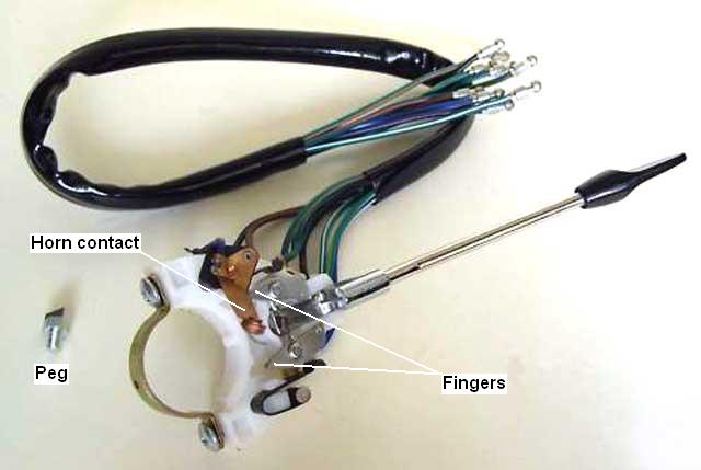
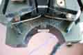
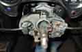
August 2023: Replacing the indicator/lighting/horn stalk on a pal's 78 (indicator contacts not functioning) with a new Lucas-boxed unit the mounting collar on the switch has a tab that is supposed to locate into a cut-out on the column outer. This tab can clearly be seen on the earlier switch (above the legend 'Contact fingers') and prevents the switch assembly from rotating about the column outer as the stalks are operated. Or it should but the tab on this new switch will not go into the cut-out, I think I can feel where it is trying, but is maybe too wide. On a subsequent visit I was determined to resolve this so took the switch off and did a trial fit of the old switch which went straight into the location notch. Took that off and put the new one back on ... and that also went straight into the location notch! Weird.
Cancelling:
 For cancelling, cars up to chassis number 187211 (basically 1970 models that began at chassis number 187170 in September/October 1969) had a peg screwed into the column. After that until 1977 the steering column has a clip which is a tight fit but can be slid round to the correct position. For 1977 on a different arrangement was used where the steering wheel itself interfaces directly with the indicator switch.
The inconvenience with the early peg is that the whole column has to be turned in the UJ to get the correct alignment, and then the wheel turned on the column, whereas the clip can just be slid round to the correct position. Both types slide under fingers on the switch and lift them out of the way as you make the turn. With the early type as the wheel is returned the peg catches the metal finger, which lifts up the spring that is holding the stalk to one side, and the stalk should return. June 2015: Note that this type of column inner slides freely in the tube and if removing and refitting or replacing the column as a whole you may have to adjust the position of the outer in its clamp brackets, i.e. slide it up or down relative to the inner, to get the indicator switch in the correct position relative to the cancelling peg, even though the switch position on the tube can be adjusted to some extent. The position of the inner is determined by the U-joint and rack.
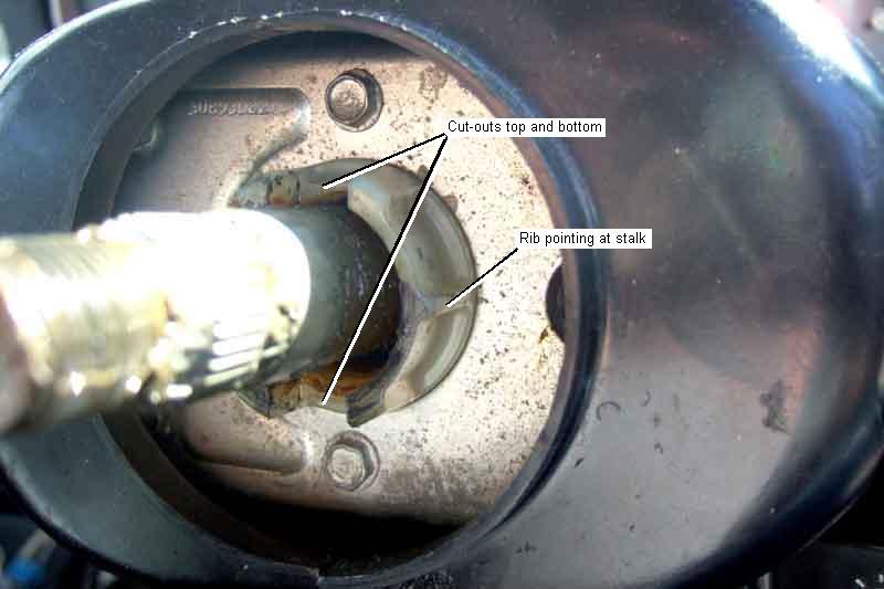
I've always had my clips facing the indicator switch with the wheel in the straight-ahead position and that way the wheel only needs a 1/4-turn in order to cancel when the wheel is straightened again. However three people on the MGOC MGB forum stated that their pegs face away from the switch, and the wheel needs to be turned 3/4 before it will cancel the indicators. The 77 and later indicator switch has a collar that is continuously rotated by the wheel and has an identification rib on one side of the collar. If that is facing the switch then again only a 1/4-turn of the wheel is needed before it will cancel as the wheel is straightened. If it faces away from the switch then it needs a 3/4 turn before it will cancel. Obviously off the car it can be positioned anywhere, but having looked at half a dozen suppliers photos they all show the rib facing the switch, so I'm pretty sure that is how they should be on the car. Also checking on my Mercedes A-class that only needs the wheel to be turned 45 degrees to hear the click of the cancelling mechanism (how agricultural ...) which will then cancel the indicators as the wheel is straightened.
 On the later type of indicator switch with plastic fingers the cancelling cam engages with the end of the finger and physically pushes the switch back to the central position. The fingers can wear such that the cancelling cam just lifts the fingers up again rather than bearing on them to cancel the switch, as well as the fingers having broken off or the cam being in the wrong place or missing.
Note that the clip-type cancelling cam or striker changed twice - once in June 73 on 4-cylinder cars from BHH254 to BHH1301, and again in September 74 for rubber bumpers to BHH402. This later change was for the full energy-absorbing column and column-stalk mounted OD switch that V8s had always had, but neither column nor switch seem to have changed on 4-cylinder cars in June 73. Roadwarrior says one was taller than the other, but he also says that when that is fitted to the wrong car the problem is that it causes the indicators to cancel as you start making the turn as well as when you straighten up again. But that is a different problem to the one that led up to him making that comment on the MG Enthusiasts Forum - non-cancelling - and may be the same cause but in the other direction i.e. the lower cam fitted where there should be the taller one. I've had to build-up the one on Bee, possibly after I changed the switch but I can't be sure. The V8 with the original switch (not changed by me at any rate) and striker has never been a problem.
February 2020:
 I get both cowls off and compare the cams and columns. The upshot is that the V8/RB cam is 'taller', but as well as that the column shaft is wider. So whilst in error the CB cam could perhaps be forced onto the V8/RB shaft it may well not be tall enough to push the indicator switch fingers back. Also whilst the V8/RB cam being taller may operate the CB indicator switch better, it will be a looser fit on the smaller column so may not stay in place. Possibly 'pinch it up' enough to grip, but the curvatures would still be different.
Update September 2007:
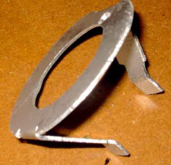
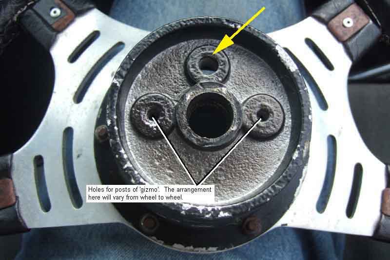
 1977 (and later) model-year cars have a special wheel boss with two projections that engage with a cancellation collar on the indicator/turn switch itself. In some ways this 77-on arrangement is best because all that needs to be done is to correctly align the steering wheel for the straight-ahead position. But if an after-market wheel is fitted, or if the later dual-stalk column switch is fitted to an earlier column, the wheel won't have the necessary protrusions to engage with the slots in the cancelling collar. The later clip could possibly be fitted to the column shaft, but is too wide to fit in one of the slots in the cancelling collar. A peg screwed into the column shaft would work, but I would draw the line at drilling a hole for it. On a friends car with a non-standard wheel I made a part out of a bit of scrap metal which joined together two handy holes in the back of the wheel boss, to the two slots in the switch cancelling collar.
 Shortly before getting my hands on this 1980 UK model Barrie Robinson was seeking advice on cancelling indicator/turn switches on his car, which is a bit of a mish-mash of years, and he wasn't sure which column he had. He had bought a new 77 and later switch as the old one broke, but having a Moto-Lita wheel was left with this problem and didn't really want to splash-out for a new switch. I sent photos of what I had done to him, which gave him the ideas as to what to do with his wheel, making a neater job of it than I did.
June 2018:
 Another possibility where there is an existing through-hole in the boss, is to use a rod or bar in the hole to engage with one of the slots in the indicator switch. Pre-1977 and after-market wheels may have a suitable hole, originally used for the centre horn-push pencil or connection wire, once the slip-ring for the horn connection is removed.
Where is the flasher unit? April 2020
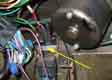 Indicator flasher units seem to be in much the same place for various years and markets, to the left of the wiper motor. Originally the hazard flasher and its fuse were behind the centre console. Eventually - probably 1977-on - the fuse moved to a more logical (and accessible) position below the fusebox, and the flasher unit to beside the indicator flasher.
Dash tell-tales: October 2019
 Mk1 cars have two wires to the tell-tales as they have connections to both the flasher unit and the indicator switch and need insulated bulb holders 37H5181 similar to the ignition warning light. The bulb is an MES E10 screw-fitting (GLB987).
 Mk2 CB RHD (and LHD without the padded dash) cars have a holder with only one wire to the tell-tale (13H1924), the holder picking up an earth from the bracket on the back of the dash panel. The same MES E10 bulb as above. In front of this bracket is a tube which concentrates the light onto a green plastic lens, which is positioned behind an arrow-shaped cut-out in the dash panel.
 Early padded dash have a unique dash fitting and a two-wire (green/white or green/red and black) claw-type bulb holder similar to Mk1 cars, and takes the same MES E10 bulb.
 Later padded-dash, V8s and rubber bumper tin dash have a tubular lens pushed into the front of the dash panel, secured from the back with a spire clip retainer. The bulb holder has two wires, the second providing an earth as the mounting panel is insulated, and pushes into the lens from the back. The bulb is a BA7S (GLB281) i.e. bayonet-type.
From 1977-on the Parts Catalogue shows the same bulbholders and retainers securing the four warning lights round the fuel gauge. With the smaller squarer rocker switch the rear fog-light switch has an internal bulb (LES GLB921 screw fitting) for the tell-tale function showing orange as well as the night-time illumination showing green.
Indicators/turn signals
Hazards
The curious case of the fuel pump that didn't click when turning on the ignition February 2022
The first and easiest step for either flasher unit - once you have located - is to bridge the two wires at the unit - green and light-green/green for indicator and brown and light-green/green for hazards. If the lights now come on with the appropriate switches operated (ignition on and indicator switch operated to either side for indicators, hazard switch for hazards) but don't flash then the flasher unit is faulty and these are GFU103 or FL5 for Mk1 indicators, SFB118 or 8FL for Mk2 and later indicators, and GFU2204 or SFB130 for hazards. But if still no lights, read on.
Indicators/turn signal faults: Updated July 2015:
Apart from that where indicators light but don't flash one side this printable schematic and chart should help you to plot the voltages through your circuits and locate any bad connections. You don't need the engine to be running but it is more realistic if it is from a voltage point of view, and won't flatten the battery (dynamo-equipped car may need a bit of fast idle to extinguish the ignition warning light). If you don't run the engine (saving fuel) then disconnect the coil to prevent it overheating which it almost certainly will do with the ignition left on for a long time (with the exception of some electronic ignition systems). Non-flashing could be due to a failed flasher unit of course as well as bad connections. An ammeter in place of the indicator flasher unit should ideally show 3.5 amps, if it shows 3.2 amps or higher but doesn't flash then the flasher unit is probably faulty. With bad connections a new flasher unit may well start them flashing again, but this can simply be due to its being new and more sensitive, as it 'burns in' they will probably slow and stop again. If you are investigating slow flashers, and they continue to flash slowly, it makes measurements easier if you bridge the two connections on the flasher unit to stop it flashing. See here for the results of the tests on Vee.
This sensitivity to current was deliberate to give warning to the driver if a corner should have failed, otherwise traffic around you may not realise you are preparing to turn. Modern flashers use electronics (instead of a heated bi-metallic strip) and flash rapidly if one of the main lamps fails and are nowhere near as sensitive to slightly bad connections as the original 2-pin units. Some people fit a modern electronic flasher to their classic car when they get slow flashing from poor connections, not realising that they will still there and causing the lights to be dimmer than they should be. A pal fitted one of these a while ago, but on doing voltage tests for another issue more recently found he was getting less than 8v at each rear light. Whilst fitting an electronic flasher unit to get round 'slow flashing' problems because of bad connections may seem to have done the trick - temporarily, eventually you may have to find and fix the root cause(s), you might as well do it now and get brighter lights. Be aware that some aftermarket types flash at the same rate regardless of current and therefore give no warning of lamp failure, so if you wimp-out and fit an alternative flasher unit disconnect one of the bulbs with it fitted and make sure that the flashing speed changes. If not, you run the risk of being rammed up the back because the person behind had no idea you were going to turn so didn't expect you to slow down. Electronic flasher units have their own problems - or at least people have problems with electronic flashers, as I have known of at least two occasions where the driver was blissfully unaware that because one side flashed at twice the rate of the other it indicated bulb failure, they hadn't even noticed! As Einstein reputedly said "Only two things are infinite - the universe and human stupidity, and I'm not sure about the former." Likewise LED Bulbs have their own issues.
As mentioned before the indicators circuit is: Battery - starter cable - brown circuit - ignition switch - white circuit - fuse (note 1) - green circuit - hazard flasher switch (note 2) - green circuit (note 3) - indicator flasher - light-green/brown circuit - indicator flasher switch - green/white (RH side) and green/red circuits (LH side) - indicator bulb holder - indicator bulb - indicator bulb holder - body earth (note 4) - battery earth cable. CB cars with twin-6v batteries also have the battery link cable. ![]()
Note 1: Later cars have an ignition relay and white/brown circuit between the white circuit and the No. 2 fuse.
Note 2: The indicator flasher is wired via the hazard switch so that it is disconnected when the hazard flashers are turned on, and only works when the hazards are turned off. This prevents the outputs from the hazard and indicator flashers from conflicting with each other, but more importantly prevents the hazards feeding power back through the indicator switch, indicator flasher, green circuit, fusebox and onto the white circuit and so energising the fuel pump and ignition (my thanks to Mark Childers for pointing this out). So don't be tempted to bypass the hazards switch if it is that which is causing your indicators problems.
Note 3: The 'green' circuit from the hazard flasher switch to the indicator flasher should really have its own tracer as it is no longer part of the 'real' green circuit.
Note 4: Rear light clusters on all cars and front indicator/parking light clusters on CB cars have the cluster picking up an earth from their physical fixings to the body. RB front indicators have a wired earth shared with the headlights/front parking lights.
Typical indicators faults can be "They don't work at all" or "They don't work on one side" or "They light but don't flash or flash too slowly" or "They flash but so do other lamps" or "They don't cancel".
Yes, they all work - if all lamps are flashing then that indicates that there is continuity at the lamp ends of the green/white and green/red circuits, although they could still have connections bad enough to affect the rate of flashing of the indicators. Now check the green circuit for 12v through the hazard switch (which needs to be off. Note that dirty contacts in the hazard switch are a frequent cause of indicator problems that affect both sides) and the indicator flasher to the indicator switch (if you suspect the flasher unit itself just bridge its two contacts. The lights should light, but not flash). Then through either the green/white or green/red circuits out toward the lamps. Pay particular attention to any volt drops anywhere except across the indicator flasher itself, which typically drops about 0.25 volts when the lamps are lit (and 12v when they are in the 'off' part of the cycle).
No - see below.
"They light but don't flash or flash too slowly" Updated April 2013
Investigating slow or non-flashing where the cause is low current is probably the most difficult electrical job on the car, and can be very frustrating, the only way to deal with it is in a logical and methodical manner. As well as being the most sensitive circuit on the car to bad connections, there are more connections in this circuit than any other - around 30 just to flash two bulbs on one side! Any electrical circuit will 'lose' some voltage in wiring and connections when carrying current (and ours have up to 50 years of oxidisation to contend with), so my recommended methodology involves taking voltage measurements at certain points along the circuit, all of which can be done with minimal disturbance to wiring and connections. By working along the circuit you can spot a sudden drop in voltage, which means there must be a problem between this point and the previous one. However rather than testing every single one in strict order, it's more efficient and will save time if you test certain key points first, then use that to decide whether the intermediate points need investigation or not. For example if you only see a 0.1v drop between two points that have three other connections between them, there is no point testing those three other connections. The first half of the tests are all on circuitry that is common to both sides, but after the indicator switch you needs to take one set of measurements for each side, and shortly after that one set for each corner. Whilst slow or non flashing both sides will lead you to think it must be a common problem, it's just as likely for there to be problems on both sides.
The ignition will be on with the engine stopped for these tests, so the coil should be disconnected to prevent that overheating. It also reduces the load on the battery. With 3 amps or more you will still be discharging the battery noticeably, and you will need to know when to stop or whether to connect a battery charger during the tests to avoid discharging it too much. The other thing is that while testing, and discharging the battery, its voltage will be dropping anyway, so you need to take this into account when you are testing along the circuit by periodically remeasuring the first test point, or you could be led to think there is more voltage being lost the further you go along the circuit than there actually is. If you only operate the indicator switch long enough to take each measurement, and turn it off while moving the meter from point to point, you will minimise the drain on the battery. Finally it's not going to be easy measuring voltage on either an analogue or most digital meters if the flasher is going, even slowly, so it makes sense to bridge the green and green/brown wires at the flasher unit so the lamps are glowing continuously while taking the measurements.
This schematic and list should help you plot the voltages through the circuit. The list works along the circuit connection by connection, but some are conditional i.e. only performed if a test earlier in time, but later in the circuit, shows a bad connection. You will probably end up with a progressively dropping voltage as you go from point to point. Writing these down you will see where the biggest drops are, and tackling those first will give you the biggest improvement. That way, when you get fed up, the worst ones should have been done! Note that the last few are earth tests so in an ideal world these will all be zero, so switch your meter to a lower range if appropriate. Any voltage seen in these tests indicates a bad earth. Note that as well as the centre contact of the bulb being a possible cause of a bad connection, which is inaccessible without removing the bulb, there is also a connection between the bulb base and the holder, the holder and the light unit, and the light unit and either the body (chrome bumper front lights and all rear lights) or the wired earth (rubber bumper front flashers), all of which can cause problems.
The attached shows the measurements on my V8, not because I had a problem but as a practical indication of the sort of figures you might get. The first thing to say is that I have a quality AVO analogue meter, and a cheap digital, and I got some weird and inconsistent results between the two. The first problem was that at the battery connections the analogue read 12.2v but the digital only 11.2v, both with everything switched off. I've seen this before with a digital dash voltmeter - which rather goes against the point of its existence. Subsequently I compared those two with a third, analogue Gunson's instrument, and with all three connected at the same time I got 0.5v difference between the original two, and the additional analogue instrument was lower again! It would be tempting to say the digital must be the most accurate, and the AVO reading high and the Gunson's low. But when doing earth tests at the first light unit (right front) with the digital it didn't matter whether the probes were connected or disconnected, the display kept hunting around the 200-300mV area. If I connected the probes together, or even put my thumbs on them, the reading stepped down to zero. So I tried my AVO and that immediately showed 0.9v on the bulb base, holder and light unit. So that, together with previously having found it increasingly more inaccurate as the resistance value got higher, means I don't have full confidence in it. Nevertheless, it is comparative values along the circuit that we are going to be looking for rather than absolutes, and as the digital is much smaller than the analogue I used the digital to move around the car and left the analogue connected to the battery so I could monitor it's reducing voltage through the test process. In the event I got half way through without seeing any drop (from 11.9v under indicator load) so stopped recording it for a while. I checked again near the end and it had dropped to 11.3v, after maybe 3 hours of switching the indicators on and off and moving from point to point.
"They flash but so do other lamps"
"They don't cancel" Updated September 2007
For both peg and cam types, with the wheel straight-ahead the peg or cam should be pointing at the middle of the indicator/turn switch. For the 77 and later type there is a rib on one side of the cancellation collar, and again this should be pointing at the middle of the switch. If the peg is in the wrong position on the shaft to cancel the switch correctly the column shaft, UJ and rack shaft have been incorrectly assembled. The UJ is clamped onto each shaft with a bolt, and this bolt passes through a cut-out in the shaft so that even if the bolt becomes loose the shaft cannot pull out of the UJ (the bolt has to be completely removed to withdraw either shaft from the UJ). However, although the column shaft only has a notch for the bolt, meaning that it can only be inserted into the joint in one position, the rack shaft has a groove machined all the way round so that it can be assembled in any position. Use this feature to get the peg in the correct position. You will probably then have to alter the position of the wheel on the column shaft (click here for how to remove the steering wheel) to get the correct 'straight-ahead' orientation of the wheel.
Problems can be caused by worn or broken fingers on the switch. Building up the height of the cam or judicious bending of the fingers with heat (don't break them!) can compensate for this. Broken fingers may be able to be jury-rigged - you will have to judge.
The sliding cam can become loose on the column and slip round instead of cancelling the switch. You could try removing the cam and closing it up a bit making it a tighter fit on the shaft, or degreasing and roughing-up both surfaces, gluing, or as a last resort drilling a hole and fitting a small screw through cam and shaft (but drilling holes in things like steering shafts isn't really recommended).
Note: The indicator flasher is wired via the hazard switch so that it is disconnected when the hazard flashers are turned on, and only works when the hazards are turned off. This prevents the outputs from the hazard and indicator flashers from conflicting with each other, but more importantly prevents the hazards feeding power back through the indicator switch, indicator flasher, green circuit, fusebox and onto the white circuit and so energising the fuel pump and ignition (my thanks to Mark Childers for pointing this out).
These tests should be done with the ignition off, and all wiring connected, except where specified otherwise.
First check for 12v on the brown and light-green/brown terminals of the hazard flasher. Note: North American cars prior to 1972 have a third terminal on the hazard flasher with a light-green/purple wire. From 1972 on this wire was on the hazard switch. This is for the hazards tell-tale and should be ignored in all tests.
12v on the brown but not the light-green/brown - hazard flasher faulty
12v on both - move on to the hazard switch
12v present - operate the switch and check for 12v on the light-green/brown again
12v still present at the light-green/brown at the flasher but not at the hazard switch - bad connection between these two points. Note late model cars have a multi-way plug and socket concealed behind the dash.
12v flashing on and off with the indicators - hazard switch faulty. This can be confirmed by cancelling the indicators and turning the ignition off again, then bridging the light-green/brown to either the green/red or the green/white (or both together) wires that go to the hazard switch, removing the plug from the switch if required. If the remainder of the hazard circuit is good it will start to flash the lights.
Indicator Flasher Replacement Updated June 2024
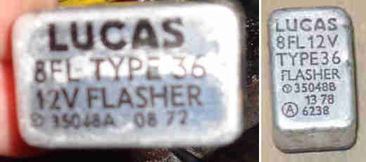 Fraught with pitfalls even as far as the original as far as the two-pin Mk2 MGB type is concerned. The 'Type' number on original Lucas 8FL indicator units tells you what bulbs they are designed to flash, and there are Type 36, Type 41, Type 43 and Type 51 where the type number specifies the current they are designed to work with i.e. 3.6 amps, 4.1 amps, 4.3 amps and 5.1 amps, each with a different part number 35048, 35049, 35057 and 35052 respectively. The colour of the printing also varies - Type 36 are usually black, Type 41 yellow, Type 43 blue, and Type 51 green but seemingly not exclusively so. The reason for the subtle variation between units is that this design of flasher unit is very sensitive to current flow, which is dependant on the number and wattage of bulbs, and will give an incorrect flash rate when used on the wrong vehicle. The MGB has two 21w bulbs at the corners and one 2W tell-tale on the dash. Together this comes to 44W and at a nominal 12v this results in a current of 3.6 amps and the type 36 flasher unit is the correct one to use. Type 41 are expecting 4.1A i.e. 49 watts and that needs an additional 5W repeater flasher bulb front wing to flash at the correct rate (the other two need even more bulb current) and on the MGB they will either flash slowly or not at all. Current-stock generic no-name flasher units labelled '21WX2+5W' are effectively Type 41 and even with the engine running i.e. dynamo/alternator charging they can be flashing at below the legal limit which is 60 fpm, and those labelled '(2X21W)+(6W)+(2W)' as Lucas SFB115 will be the same unless you connect up additional bulbs somewhere! However three SFB115 I tried had hazard flasher internals instead of indicator internals which raises two completely different issues, and so-called 'universal' flasher units are the same.
The upshot is that the MGB needs 8FL Type 36 30548 only available as NOS and rare, or (supposedly!) Lucas 35048. Googling that brings up loads of motorbike sources, one ordered for testing. However on arrival it is effectively a hazard flasher as it only comes on after a pause instead of immediately, and it doesn't change the flash rate on bulb failure. So as three SFB115 I purchased did exactly the same which I put down to a manufacturing error, I'm wondering now if they are all deliberately like that to get round complaints of slow flashing! Maybe the only alternative to NOS 8FL Type 36 (rare!) is the next generation electronic flasher unit for filament bulbs used in the 80s and 90s which is nowhere near as sensitive to voltage and current and has the bulb failure warning which in this case flashing the remaining bulb at double-speed when one corner has failed. But remember, if the slow flashing of the standard flasher unit is down to some high-resistance connections that will be making the bulbs dimmer than they should be, even though they will flashing at a good rate. As an aside my Mercedes A-Class with LED lighting has the indicators lighting immediately for both indicators and hazards, good flash rate engine not running, don't know about 'corner failure' though.
July 2024: I'm beginning to think I dreamt the flashing at double speed if a corner has failed as flasher units for Rover models from 1983 such as YWT10003 state "21Wx2+(5W) 21Wx4+(2X5W) Max.98W" which surely (?) means they cannot detect bulb failure when used as indicators. But Googling throws up loads of references that flashing at double-speed does show that a corner has failed. Digging deeper into some of those the flashing is controlled by a computer, but others such as a 1997 Discovery where having fitted LED light units they now flash at double-speed and they are being told to fit resistors to simulate the additional current of filament bulbs, and they apparently use one of the YWT10003 flasher units! So maybe those units are really clever in that with 2, 3 or 4 bulbs they flash at the correct rate, but with only one they flash fast! One purchased - unlike the 2-pin flasher unit which can be connected either way round the three terminals - two for the original wirs and an extra one for an earth - have to be connected correctly - green (12v supply) to 49, green/brown (indicator switch) to 49a, and earth to 31. Whilst it does flash at double-speed with one corner disconnected, it doesn't come on immediately the switch is operated but only after a delay. But the delay is very brief and flash speed is good even with the engine not running, so on balance probably the best option. But as I say above if the slow flashing of the standard flasher unit is down to some high-resistance connections that will be making the bulbs dimmer than they should be, even though they will flashing at a good rate.
However having tested it in Bee with a buzzer in circuit to give a louder audible warning it is buzzing faintly all the time the indicators are off, so the output terminal must have a partial path to earth - probably part of the electronics and bulb failure warning, whereas with the original unit the only path to earth is via the indicator switch to the bulbs. It might be possible to use a diode to block the earth from the buzzer, but because that results in a volt-drop that would reduce the brightness of the bulbs slightly so not a good idea. A pair of diodes on the output of the indicator switch (to prevent cross-feeding from one side to the other) would work, but then the buzzer would sound with the hazards.
May 2016:
 I'd noticed Bee's flash rate was getting quite sedate, even driving along i.e. full voltage, and they wouldn't flash at all with the engine stopped apart from a brief click as you switched from one side to the other. I did my voltage tests and with one exception there was very slightly less voltage lost end-to-end than Vee, the one exception being in the 'new' indicator switch assembly which was slightly higher, but that only brought it back to the same as Vee overall. Two 21w bulbs directly on the output of the flasher unit were the same, the only thing that got them to flash - albeit slowly - (with the engine off remember) was when I added a 2.2W bulb to the 21W bulbs. So I reckoned the 1978-vintage flasher unit was probably getting tired, and ordered a new one from the MGOC. Generic and no-name I was surprised to find that was twice the height of the old one labelled '2 x 21W + 5W'. Installed it does flash with the engine stopped albeit quite slowly of course, although I'm sure it's quieter. However I know these units are slightly more sensitive when new, which reduces after a short period of use to a 'long term' flash rate. After a weekend away it definitely is quieter, but more importantly noticeably slower then the old unit when the engine is running. The old unit gives 80 flashes per minute, the new one only 64, which is only just above the MOT minimum of 60 flashes per minute. Roger Parker said that in these days of frantic traffic one needs them flashing faster rather than slower, and recommended that the club shop send me another. They did, but that is even slower at 56 fpm and so below the legal minimum. I did some more tests with my three bulbs, and also powering the flasher unit off the purple circuit, which when combined eliminates almost all the cars wiring, on both the roadster and the V8. The upshot was that the fastest I could get a new flasher to run at was 76 fpm which is just about OK. The original unit connected the same way was flashing at 116 fpm, which is almost too fast, the legal maximum being 120 fpm. Whereas the original unit showed a 60% increase in flashing rate between the two extremes of connection, the new units showed only a 15% and 20% increase. Neither do the new units exhibit the slight slowing when applying the brakes that the original units do. Whether this is just because they are new, or whether the bigger can means they are different inside I don't yet know. The new units do seem to be able to ignore connection and wiring resistances much better than the original units, much as the 3-pin electronic units do. If only they flashed at a better rate when connected normally, they would be an improvement but as they are I think they are incorrect in this application. I've sent the results of my tests to Roger, and await developments. In the meantime I opened up one of the new flasher units to find - not surprisingly - it is the same as another I have. I tried tweaking the contacts, which did make it flash at an acceptable rate at 12v, however with the engine running i.e. at 14v it's initially very erratic either galloping or not flashing at all before settling down to an acceptable rate, so on balance I have put the original unit back in. It seems to me this unit would only be acceptable if you added a 5W bulb or 30 ohm resistance to the circuit to draw the current that this unit is expecting. You could add one to each 'leg' of the indicator circuit i.e. one per side, however a single one connected on the output side of the flasher unit would do the same job - at the 'expense' of the bulb glowing all the time or the resistor taking current all the time the ignition was on even when the indicator switch hasn't been operated. This is because the indicator flasher is 'normally' closed, to give the immediate lighting of the lamps at the corner of the car as soon as the switch is operated.
July 2018:
 Happened to come across an NOS 8FL indicator flasher in a red bubble pack for �5.50 on eBay so snapped it up. Ticks faster than either of the units that came with Bee and Vee, and on Bee flashes with the engine stopped, so far so good. However it's noticeably quieter, so a couple of times I've found I've left it on after a turn. September 2020: while testing other aspects of the lighting the indicators have gone back to not flashing with the engine off, just one tick changing from one side to the other as before, proving that there is a 'burn-in' period and they deteriorate slightly for the bulk of their life. Still plenty fast enough with the engine running. Subsequently I purchased two more supposedly NOS but without packaging and whilst they lit they didn't flash even at charging voltage. Took it up with the supplier who pointed out mine was type 36 and his were type 41 which needed an additional 5W repeater on the front wing to work correctly. Mea Culpa, but he did refund me on return.
July 2023: Just lately the indicators have been noticeably slower, so I was thinking that perhaps the NOS 8FL above had aged a bit now and was as bad as the others. I still have the after-market ones that were slower than an old FL, tried them and they were no better, in fact one of them kept blowing the fuse because one of the terminals had pushed through the plastic base when I was fitting the spades and was shorting-out internally. That was because when I pulled the spades off the 8FL they didn't seem very tight so I had pinched them up a bit. Went back to the 8FL and with the tighter connections it speeded up significantly, and has remained so.
Note that while modern 3-pin electronic flasher units don't suffer from the slow flashing problem, neither do they warn you of worsening electrical connections that will be resulting in dimming bulbs.
Adjustable flasher units: June 2024 The question of indicator flasher units cropped up on the MGOC forum again and I recommended looking for NOS 8FL as bought a few years ago. I found an eBay seller with two, so bought them, but on receipt whilst they lit the bulbs they didn't flash, even with the battery charger connected. I complained sending a photo of my existing unit which worked (of course), and he said that's because mine is a Type 36 whereas his are Type 41 and only suitable with additional bulbs, which led to the paragraph at the top of this section, so returned them for a refund. Whilst looking to see if I could find any more I discovered loads of 'adjustable' types advertised for motorcycles, saying they were suitable for 2X21W filament bulbs or LED bulbs which take a very much lower current, just turn the adjuster on the base for anywhere between 50 and 200 flashes per minute. The first one I came across was �15, but referenced in the eBay ad were loads at �5 and less, so one of those was ordered for testing. But they're exactly the same as the Lucas 35038 above with delayed bulb lighting and no bulb failure i.e. they are no better than hazard flasher units except that you can increase the flashing speed to whatever you want.
LED indicators Updated December 2017
Secondly they will not work correctly with either the original thermal or 'standard' electronic flashers - in the former case both bulbs will light but not flash, in the second case they will flash but very quickly indicating bulb failure. Some vendors supply a load resistor with LED lamps so that the original flasher units (thermal and electronic) flash at the correct rate, but then the 'bulb failure warning' feature in the original flashers will only detect resistor failure, not LED or wiring failure!
You can get indicator flasher units specifically for LED lamps which should flash them at the correct rate - 2-pin and 3-pin where the third pin goes to earth. But again, these do not tell you when a corner has failed and so are equally as unsafe as load resistors with standard flashers, and with some types if you connect more than one filament bulb to them you will burn them out. Also some contain a relay and make an audible click and some do not. April 2018: Out of interest I purchased a 3-pin type advertised as being for 0.02A to 20A so apparently suitable for anything from all-LED to all-filament indicators and hazards. But on all-LED they just flashed once, even though there was a current of 0.9A. It needed an filament tell-tale bulb added to boost the current to about 1.3A before they would flash repeatedly. Ends
A supplier of a 2-pin type claims that they are the units fitted to BMWs (but at only �14 I find that unlikely). Also I'd be surprised if modern cars were allowed to get away with there being no indication of failure as IMO it is a significant safety hazard. On questioning the supplier they defended themselves by saying LED bulbs were much less prone to failure than filament which is correct, but there can still be wiring or connector failure as before which will have the same effect. They defended that by saying failure warning types were being developed but had no date for availability, something I find difficult to believe when they are supposed to be OE units. I've not been able to establish yet whether OE use does or doesn't have failure warning, but recently I was behind a Range Rover with these bulbs which stopped in the middle of the road prior to turning across the traffic without indicating. Cussing the driver under my breath I then noticed as he turned that the side marker was flashing at the correct rate! Which indicates (ho ho) that Land Rover at least may well be fitting these with no failure warning. In theory cars should detect disconnections in the wiring right up to the bulb holder as there is a load resistor inside the 'bulb', but that still won't detect failure of the light emitting elements, and they do fail, especially after-market components.
Note that if you fit LED lamps and the LED indicator flasher unit you will probably need to change the hazard flasher as well. Whilst hazard flashers are designed to flash anything from one to four 21w filament bulbs, they do still need a certain amount of current flowing through them, and the current from even four LEDs can be less than one filament (21 watts i.e. 1.75 amps). My 'standard' hazard flasher will - just about - flash a single 6w filament but it won't flash two 21W-equivalent LEDs.
About the only excuse for fitting LED indicators is they can be left operating for a lot longer in the event of a breakdown or accident without flattening the battery - unless you have installed load resistors at the same time and retained the original flasher unit!
Adding hazards to earlier cars
Hazard flashers were standard in the North American market from the start of Mk2 production in late 1967, but not added to other models until the either the 1974 model year or rubber bumpers, it's not entirely clear. Before adding hazard flashers to earlier cars it is vital to understand that the hazard switch must disconnect the standard indicators in some way, otherwise it is possible to have the fuel pump and ignition powered even with the ignition off and the key in your hand, which is obviously a serious safety hazard (pun not intended) especially in the event of a collision. If a hazard circuit is simply added to the indicator wiring then with the hazards turned on and flashing the lights, if the indicator switch should happen to be operated, power will feed backwards through the indicator switch, indicator flasher, onto the green circuit and through the fusebox onto the white circuit. Factory flashers power the indicator flasher unit through the hazard switch in the 'off' position, disconnected when the hazards are turned on, for retro-fitting this reverse current path can be disconnected either with a suitable switch, a relay or blocking diode.
Options are:
- Obtain a factory-style rocker switch and wire it as per factory wiring. This will require diverting the green circuit that feeds the indicator flasher unit as well as connecting to the green/white and green/red lamp circuits, and connecting the new hazard flasher via an in-line fuse to a brown circuit. A good option for UK cars with the earlier style of rocker switches as there is an empty space in the centre console, and could also be used on toggle-switch cars in a supplementary panel.
- Use a generic double-pole double-throw switch with the green/white and green/red wires from the corners of the car connected to the two common terminals, the normally closed contacts connected to the green/white and green/red wires from the indicator switch, and the normally open terminals connected together and to the hazard flasher. Requires diverting both the green/white and green/red circuits which can be done at the bullet connectors between the main and rear harnesses in the engine compartment if you don't want to cut wires.
- Use a generic on/off switch and two relays, one relay tapping into the red/green and red/white wires for the hazards, and the other disconnecting the indicator circuit when the hazards are in. This disconnection can be done where the light-green/brown wire connects to the indicator flasher unit.
- Use a generic on/off switch and diodes to connect the hazard flasher to the green/white and green/red circuits via two diodes, with a third blocking diode in the green circuit feeding the indicator flasher unit.
Note: Inserting diodes into circuits results in a small volt-drop which means that slightly less voltage will be reaching the lamps. With incandescent bulbs there there will be a small reduction in brightness, it's up to you whether you consider this to be acceptable, MGB indicators are not the brightest to begin with. Note also that diodes can fail, disabling either hazards or indicators, or could cause both sides to flash with the indicators and damaging the indicator flasher (but then so can relays and after-market wiring). - Hazard flasher conversions are available as after-market add-ons, make sure these do disconnect or block the existing indicator circuit to prevent this reverse current flow. The vendors may have no idea what you are talking about, so always test after fitting by looking for 12v on the white or green wires at the fusebox with the ignition off, hazards on, and indicator switch operated to one side or the other. If the circuit is not blocking this reverse path you will see 12v switching on and off as the hazard flasher unit clicks. It's up to you whether you are happy to use it or send it back. Note that a kit advertised in the MGOC 'Enjoying MG' magazine showed the detail of the connections in the October 2013 issue and did not interrupt the indicator circuit.
There is also the hazard tell-tale to consider. According to the schematics UK cars don't seem to have had these (why would you need one when both the dashboard indicator tell-tales will be flashing anyway?), but North American spec always did. From 1972 this was fed by a light-green/purple wire off one of the contacts of the hazard switch and a 2-wire hazard flasher unit was used. In this case only the first option above can be used, as the tell-tale needs to be isolated from the hazard flasher unit and the indicator wiring when not in use, and only the factory switch (or similar hazard-specific switch) does this. The schematics show that from 1968 to 1971 a 3-wire hazard flasher unit was used, with the third wire feeding the tell-tale, and this type of flasher and tell-tale wiring can be used with any of the options above. 3-wire hazard flashers seem to have been used on a number of British cars of the era, still seemingly available from the likes of Rimmer, Canley Classics and others. Check they are capable of driving at least 4 21w bulbs, they may also be marked 'heavy duty'. Alternatively it may be possible to wire a tell-tale bulb in parallel with the 2-wire hazard flasher i.e. directly to its two terminals. This will flash the tell-tale in anti-phase to the corners of the car instead of in phase as with the factory and 3-terminal options, but should be legally acceptable for inspections.
Finally power to the hazard flasher must come from an always on, fused source. 'Always on' because the hazards need to be available with the ignition off and the key out, fused in case one of the corners of the car is damaged and the lamp holder or wiring is shorting out. Without a fuse this could cause a fire, adding to your woes. Factory cars were wired from the brown circuit via an in-line fuse solely for the hazard flasher, originally in the very inconvenient location of behind the centre console! Whilst it is technically feasible to power it from the purple circuit which is also always on and already fused, as this feeds the horns and other circuits accident damage may have shorted out that wiring elsewhere on the car and blown that fuse. This means that if you are going to the trouble of adding hazard flashers, a separate fuse off a brown wire is really the only sensible option.
Adding to Bee: August 2013
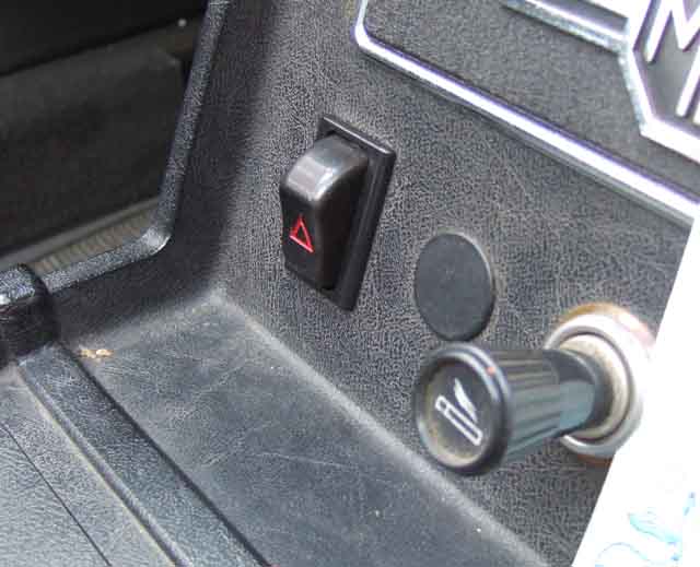 After a pal had his TR6 written off by being rear-ended, just a couple of weeks after completing a two-year restoration to make things even worse, I decide I really need to fit hazards to Bee (Vee has them as standard). The TR6 didn't have them, although in that case I don't think it would have made any difference. The car had broken down on a dual-carriageway, was only half on the carriageway and half on a grass verge next to a crash-barrier, in clear visibility on a straight road just after a roundabout, with my pal back up the road warning people to keep over. Nevertheless this ... chap seemed totally oblivious of both my pal's warning as well as the car, almost hit him, then smacked right into the TR6's off-side rear corner which caused the perpetrator to spin and roll, coming to rest on its side. But anything that might improve visibility of these, by today's standards, small cars has to be of benefit and I decide to fit hazards before going any further with DRLs which a pal and I have been pondering for some time.
August 2023: Checking Bee over prior to an MOT - lights, wipers, washers, horn. Main lights - fine. Hazards - fine. Brake lights - fine. Indicators ... no indicators. I'd only been out in her a couple of days previously and they were fine then. The hazard switch disconnects power from the indicators (as explained above) so flipped the hazard switch on and off again and the indicators worked again. Only installed 10 years using the standard switch as there was a spare position in the centre-console, they are probably only used twice a year - pre-MOT and MOT, so hardly 'worn out'. I tried the switch a few times and most of the time it worked as it should but every now and again if I switched it off slowly the indicators didn't work. Quite co-incidentally a pal I'm helping with his electrics gave me a new hazard switch of the correct type just the other day which he had bought for his car not realising it used a different switch. Fitted that, working again.
I'd had the same thing on Vee's hazards not long after buying her 30 years ago, opened up the switch and it was full of hardened grease. Dug that out and replaced with fresh, worked again and has done ever since. I'm almost certain that is the original switch. Opened up this switch, only a little grease and certainly not hard. Cleaned that out anyway and scraped the contacts (as I had to do with said pal's brand-new main lighting switch straight out of the box) and with a test meter that seems OK now, so has gone in the spares box.
When I restored Bee just over 30 years I replaced all the dash switches as the logos were a bit faded, then some years later the new main lighting switch started getting intermittent. As the logo on that was getting a bit faded I put what was almost certainly the original switch back, and that has worked ever since.
New stuff is rubbish even though it looks exactly the same as the originals.
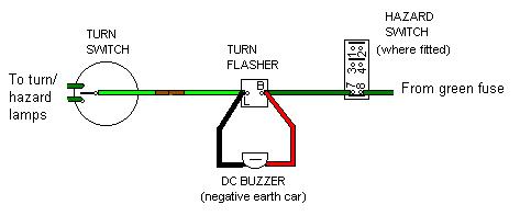 Never the loudest ticking, particularly at higher speeds in either roadster or GT, and some without the hearing sensitivity of a bat might find themselves inadvertently leaving the indicators on when they shouldn't be, you can add a buzzer to give more of an audible warning. Get a 12v dc buzzer and simply connect its two wires to the two terminals on the indicator flasher. Some electronic 'buzzers' are polarity conscious and will have red and black wires in this case, and for negative earth cars connect the red wire from the buzzer to the green on the indicator flasher and the black to the light-green/brown wire. For the earlier positive earth cars connect the buzzer the other way round. This will probably work on 'modern' cars too.
When you first operate the indicators you won't hear anything - don't panic! It is only when the lights go out on the first click of the flasher that the buzzer will sound, i.e. it operates in anti-phase to the lights. If you find the buzzer too loud you can always wrap a couple of turns of insulating tape or similar round it. However the cheap electronic buzzers make a pretty horrible sound, and even the piezo type can get annoying, so I'm experimenting with something to make a louder clicking noise with my NOS original which although flashing quicker is quieter than the old one ... watch this space!
February 2020: An enquiry on the MGOC forum reminded me that I hadn't updated this. My first thought was to wire a small loudspeaker in series with a capacitor. The theory being that although the impedance of a typical speaker is far too low to wire across the flasher unit and would affect both it and the lamps, adding a capacitor would prevent that but allow to capacitor to 'charge up' and discharge via the speaker each time the flasher contact opened and closed. I used to have a couple of speakers from small transistor radios I messed with decades ago, but couldn't find them. Got one off eBay but it was much smaller than expected and was way too quiet.
Next thought was a solenoid where the ends of the plunger were exposed, and positioned in a box or by a bulkhead the plunger would hit the sides of the box or the bulkhead so making a noise each time it operated and released (in a box) or just on the one stroke (bulkhead). Ordered one of those, but in the meantime I discovered an old GPO electronic sounder with three volume settings. Tried that and like Goldilocks and the three bears one setting was too loud, another wasn't loud enough, but the third setting was just right. It's also quite a melodic sound very different to the harsh 12v buzzer, so that's as far as I went.
The MGOC forum reminded me that I had also seen buzzers for motorcycles, including one type with a delayed response of 20 flashes or so before it started buzzing. Some of these have an additional feature that if you sit there with your brake lights on the buzzer is muted until you release them. As Dave Birkby said - "bizarre". Whilst I can understand car drivers sitting at traffic lights with a foot on the brake (instead of selecting neutral and applying the handbrake ...), do bikers habitually do that? Even though modern bikes light the brake lights from both front and rear brakes? And one motorbike forum was discussing a system where the buzzer only sounded once every ten or so flashes. Both relatively easy using a chain of bistables or JK flip-flops, should you be so inclined - four to give you a count of 8, five for 16.