


Cowl
Lock
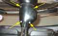
Indicator/turnswitch, Cancelling Striker and Cowl Positioning
Repairs
Column/Rack Universal Joint
Column/Rack Alignment
From 1970 to 72 the wheel for all markets had flat alloy spokes with five holes in each, changing to slots for the 73 model year because the holes trapped fingers. But only a few months later the slots were changed to depressions as the slots trapped dangly jewellery! V8s had the side-entry lock on the full energy-absorbing column, and the wheel with depressions for the whole of production. From the start of rubber bumper production all cars regardless of market got the full energy-absorbing column (crushable outer as well as collapsing shaft) with side entry lock. The components then remained unchanged until the end of the 76 model year. As the wheels and columns have different change points, and the Parts Catalogue indicates the wheels were common to all markets, V8 and 4-cylinder, they must have been compatible, so this is the third variant of splines - 1970 to 1976. I've been able to compare a 73 roadster and a 75 V8, and whilst the wheels fit on each others splines the taper seems to be slightly different, even though the change-points indicate they should be the same. With the 'right' wheel pushing the wheel down onto the taper locks it, whereas with the 'wrong' wheel even pushed down it wobbles from side to side very slightly, which is probably because the V8/RB column is almost 6mm wider. 1975 Jubilee GTs may have had an all-black wheel with a gold MG horn-push logo. Other cars built during the 1975 Jubilee year had the metal-finish spokes with the gold logo.
For the 77 model year the column and wheel (now with four rubber-covered spokes) changed, again common to all markets, giving the fourth variant - 1977 on. However this is more to do with completely different arrangements for cancelling the indicators and sounding the horn, the splines and threads appear to be the same. The MG logo was originally dark grey, then silver as standard. UK 1980 LE models had the standard wheel but with a red MG logo. North American Limited Edition models of 79 and 80 had a wheel similar to the 70 to 72 but with three holes instead of five, finger-trapping perhaps no longer being considered a hazard.
October 2013:
I have found the following list concerning North American cars which agrees with the change-points above:
| Years | Type | Splines | Thread | Socket
| 62-67� | Mk1 wire spoke | 3/4" by 48 | 11/16" X 27 TPI | 1 5/16" or 34mm
| 68-69� | Mk2 wire spoke | 5/8" by 36 | 9/16" X 27 TPI | 1 1/16" or 27mm (to be confirmed)
| 70-76� | Flat alloy spoke | 11/16" by 36 | 9/16" X 18 TPI | 1 1/16" or 27mm
| 77-80� | Plastic spoke and NA LE | 11/16" by 36 | 9/16" X 18 TPI | 1 1/16" or 27mm
| |
Interestingly the 'collapsible' columns before the full energy-absorbing allow the shaft to move freely up and down within the inner. So in any frontal impact an unbelted occupant could push the wheel forwards, collapsing the inner and crushing the switchgear, allowing more travel before hitting something solid but little energy absorption i.e. deceleration. If the collision is so severe as to move the rack rearwards the steering wheel and inner shaft would actually move towards the occupant, possibly allowing even a belted driver to hit it, although that would collapse the inner shaft. The later full energy-absorbing columns are different in that the inner cannot move in and out of the outer. An unbelted driver will probably suffer greater injury from this type of column as the wheel cannot be pushed forwards until there is sufficient force (from the driver!) to deform the structure the column is bolted to. If the rack moves backwards then the inner will shear with very little force, and no energy absorption as before. It's only if the toe-board comes back far enough to hit the bottom of the column outer that the mesh construction of the outer will do its energy-absorbing stuff, and prevent the wheel moving towards the driver. But it's difficult to see how that could happen, except possibly in a V8 where the engine moves backwards. If the impact is severe enough to deform the toe-board, even with a V8, it's difficult to see how the energy absorbing column is going to make much difference to the injuries of the driver, given that this 130kph/75G impact of an MGB with a solid concrete wall resulted in no intrusion into the cabin.
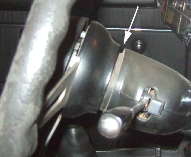
Cowl: August 2019
 Two plastic halves covering the indicator switch on CB 4-cylinder cars (one stalk), indicator and wiper stalks and ignition switch on RB models and all V8s. Where there is only the one stalk the cowl is much smaller and the two halves - top and bottom - are separated with four easily accessible screws going up from the bottom half into threaded sockets in the top half. With the later version where there are two stalks and the ignition switch the cowl is much longer as well as broader and extends under the dash and binnacle, and the screws are trickier. The two halves are one each side, with two easily accessible screws going through the left-hand half into the right-hand nearer the driver, and two more further away one in each half going into brackets on the column outer. This second pair are shrouded by the binnacle and dash as it curves round the cowl, and there is no direct access with a screwdriver. A PO had obviously removed and not refitted them on my V8 - thankfully - but even so it's not possible to get the halves off without forcing them past the binnacle which risks breakage - and they are NLA.
So the only option is to drop the steering column by undoing the three column to dash bolts - DO NOT undo the three toe-board bolts for this job. The left-hand half of the cowl can be removed just by slackening all three bolts - they undo quite a way before coming free, but to remove the half with the ignition switch needs the two on the right to be removed completely to allow the column to tilt over. Be very sure to note where any packing is present between column and dash, as that is part of column UJ alignment. Leaving the left-hand bolt fitted but with plenty of slack prevents the column dropping and putting undue stress on the UJ and rack components, so if removing the column altogether make at least one of the three dashboard bracket bolts the last one to be removed.
September 2023: Refitting a pal's 78 cowl after column stalk switch work I just could not get the two halves to line up neatly, whereas they did as two halves off the column, and it wasn't stalk switch wiring getting trapped. I removed the switches again so I could peer down inside the cowl to see what was happening - and realised that both the brackets for the inner screws were bent, one considerably, which was holding the two halves apart at that end. Repositioned - firm hand pressure was enough but there is room to get a pair of pliers in, and everything went back together neatly which was very pleasing.
The toe-board bolts just clamp a plate and rubber seal to the toe board, with a sliding fit to the column, they are not clamping that end of the column in position. Normally one would expect the seal to be pressing on the column with equal force all the way round, which will help keep that end of the column in the correct position when the upper part is disconnected or slackened. But just in case it is pressing on one side more than another, e.g. if those bolts were tightened before the column was fully aligned, it might be an idea to slacken and retighten those first to even out any forces, and only then undo the column to dash bolts.
On Vee the position of the column is such that the right-hand screw is shrouded more than the left-hand, so it's possible that just by slackening the column to dash bolts, you may be able to slide the column first one way then the other for the best access to each in turn. Note the positioning first, and put it back to that when you finish. If in doubt you may need to check the alignment of the steering column UJ.
Even with the screws out of the two-stalk type the difficulties continue, as both halves need manipulation to get them off over the ignition switch and the ends of the stalks, they don't just drop free as with the single-stalk type. Probably why the books say to remove the column complete with cowl and switches, which would be right pain if all you wanted to do was adjust the pre-77 horn brush! In fact the book says to remove the column complete with the steering wheel as well as the cowls and switches, which is stupid if you subsequently need to remove the wheel.
Steering Lock: December 2014
When does your steering lock?
Replacement
What lies inside
Types used:
| May 62 - Aug 68 | 101-152454 | Germany, Finland (Oct 67), Austria (Jan 68) | 13H4180 | 27H6237 | Use BMK2259 | Spades on switch
| Aug 68 - Dec 70 | 152455-231338 | Above plus France (Sep 69) | 13H4862 | 27H6237 | Use BMK2259 | Spades on switch
| Dec 70 - Feb 72 | 230617-275645 | Not North America or Sweden | BHA5709 | Use BMK2259 | Combined lock and switch
| Feb 72 - Sep 74 | 275646-361000 | As above | BHA5215 | 37H7708 | Use BMK2259 | Spades on switch
| May 62 - Sep 74 | 101-361000 | As above | BMK2259 | 37H5934 | Spades on switch
| Sep 74 - end | 360301-on | As above | BHM7056 | BHA5398 | Note 1 | Lock with switch, multi-plug
| V8 | 18G8905 | Note 2 | Lock with switch, bullets
|
| May 62 - Aug 68 | 101-152454 | Sweden | 13H4180 | 27H6237 | BMK2259 | Spades on switch
| Aug 68 - Dec 70 | 152455-231338 | As above | 13H4862 | 27H6237 | BMK2259 | Spades on switch
| Nov 67 - Sep 69 | 138401-187840 | North America | BHA4715 | 37H4114 | Lock and switch NLA
| Sep 69 - Aug 71 | 187211-258000 | North America, Sweden (Dec 70) | BHA5050 | BHA5056 | Alternatives | Lock and switch NLA
| Aug 71 - Aug 72 | 258001-296000 | As above | 18G8906 | Combined lock and switch
| Sep 69 - Aug 71 | 187211-258000 | As above | 18G8901 | BHA5070 | Lock and switch NLA
| Aug 71 - Aug 72 | 258001-296000 | As above | 18G8905 | BHA5070 | Lock with switch, bullets
| Aug 72 - Aug 73 | 294251-324942 | As above | 18G8984 | BHA5128 | Bullets on wires
| Aug 73 - Aug 73 | 324943-325855 | As above | 18G9064 | BHA5288 | Lock and switch NLA
| Aug 73 - Aug 73 | 325856-328800 | As above | 18G9118 | BHA5288 | Lock with switch, multi-plug
| Aug 73 - Jun 76 | 328110-410000 | As above | 18G9119 | BHA5292 | Multi-plug
| Jun 76 - end | 410001-on | As above | 18G9119 | BHA5069 | Multi-plug
| | ||||||||||||||||||||||||
Note 1a: Lock is now BHM7144 complete with switch. This is the North American lock and switch with extra grey and purple/pink wires, the original may have the grey but not the purple/pink. The remaining four wires should connect directly to the same colour wires in the main harness, but double-check before plugging in. The grey and purple/pink should not have corresponding wires in the other half of the UK multi-plug.
Note 1b: Switch no longer available, use BHA5292. Again this is the North American version as above.
Note 2: Prices for replacement lock with switch for the V8 varies from �31 to �120! If only the switch has failed it may be worth trying BHA5292 as they can be had for little more than a tenner, and if it fits it saves having to cut off the lock which cannot be done by drilling up from below like it can with the earlier side-entry locks. You would need to cut off the multi-plug, discard the grey and purple/pink wires, and solder bullets to the remaining brown, white/green, white and white/red wires.
When does your steering lock? July 2022 In a discussion about unexpected loss of oil pressure (from something like cooler or cooler hose failure, or gauge hose failure) and low pressure warning lights on the MG Enthusiasts forum one chap from North America said the warning lights are unlikely to prevent damage to the engine based on the experience of his daughter in a 1977: "She told me she had caught a glimpse of the oil pressure gauge dropping, had put the transmission in neutral, and pulled over to the side of the road where she turned the engine off. (North American specification vehicle have an ignition lock that, when moved to the off position, lock up the steering wheel...)". The upshot was the engine suffered damage from running with no oil.
The situation with the lock amazed me, and I was also surprised the engine suffered damage if it was only idling briefly. On my 73 roadster after turning back from the ignition position to the accessories position, then turning to the off position from there, a convoluted push-twist-pull procedure is needed before the key can be withdrawn. I can hear the lock tongue is released in preparation for locking as I withdraw they key, but of course it only physically locks when the wheel is turned to a position where the tongue can engage with a slot in the column. It unlocks when the key is inserted and turned towards the accessories position. My 75 V8 is different in that turning back from the ignition position to the accessories position one cannot turn the key any further until a push-button on the lock is depressed. That allows the key to be turned further to switch the accessories off and allows the key to be withdrawn - but unfortunately I cannot tell when the lock actually engages as it has never locked in my ownership! Clausager says that V8s locks 'were similar' to those used in North America at the time and had a push-button which needed to be operated to turn the key back to the locking position (marked 'O') and withdrawn, and that system was used on non-North American 4-cylinder cars in 1974: "That persisted until October 1977 when the final type of steering lock without push-button was introduced, still with a slightly different lock for North American specification cars". Posing the question on the MGOC forum two people responded one with a 78 and another with a 1980 saying it only engages as the key is withdrawn, but not whether the accessories can be turned off before that. Less easy to check on RB 4-cylinder cars as nothing is wired to the accessories circuit from the factory, unlike 71 and on CB 4-cylinder cars and all V8s where the heater fan can be used to tell when the accessories circuit is powered and when it isn't. FWIW the Golf only turns off the radio etc. as the key is withdrawn, and it is only then that the column can lock. Inserting the key does nothing, turning it disengages the lock and goes straight to ignition.
Given the number of safety features America forced the MGB to adopt over the years I'm gobsmacked that they would require a system that locked the steering wheel as soon as the ignition was turned off and before the key was withdrawn, and felt sure the original poster must have made a mistake. An American pal has a 76 and that is the same as my V8. He asked a couple of pals of his and the upshot is that they are the same as the UK i.e. the lock can only engage when the key is withdrawn, and unlocks when the key is inserted and turned towards the accessories position, which seems to be the same as the previous lock but without the push-button. Which does leave Clausager's comment that North American locks are 'slightly different' outstanding.
Incidentally while looking into this some people seem to have trouble disengaging the lock. If you have fully engaged the lock by manually turning the wheel at a standstill, then when you released the wheel it will have sprung back due to the friction of the tyres on the ground. With the lock now engaged there is considerable pressure on the side of the tongue in the slot, meaning it cannot be disengaged just by turning the key - without risk of breaking the key. You have to manually turn the wheel in the same direction as before to take the pressure off the lock before the key will turn to disengage it and turn the ignition on, but it seems not everyone understands that.
Lock replacement: Note this process is only suitable for chrome-bumper 4-cylinder cars as the thread end of the bolt can be accessed from below. On V8 and rubber bumper cars the lock covers this and the bolts have to be removed from the head end, which almost certainly needs the column to be dropped.
January 2021: But before jumping into lock replacement if the key won't come out, Crispin Allen who was faced with having to remove the column as his car is a late-model RB, tried removing the switch from the lock first ... and it was the switch that was causing the problem! Far easier to deal with, and stripping, cleaning and lubricating the switch mechanism with Vaseline was all that was needed. But if you have to proceed and are only replacing the lock, or the switch, and not both as a unit check right at the start that the new and old components do fit together and that the lock operates the switch correctly - before fitting and finding it doesn't!
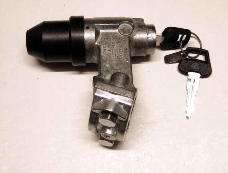
When Bee came to me there was only one ignition key so I had a spare cut from that. It worked, but over the years as the lock has worn on the rare times I use it I have found that it is very difficult to turn the lock all the way back and remove the key as normal. This earlier 'front-entry' lock needs a twist-push-twist-pull to turn the accessories off and remove the key, but this key wouldn't do that, it would come out too soon. As well as leaving the ignition switch then capable of being operated with a screwdriver, I cannot get the 'good' key in, so have to persevere with the 'spare' key - which fortunately does go back in, wiggling and turning gently until finally the lock does fully return, the key comes out as it should, and the 'good' key then works again. OK, so don't use the spare key, and get another one cut and hope that would work. Well the 'good' key is itself a copy and not original to the car or even of the same type, so what with that and 40 years of use on the original lock I decided to replace the lock now rather than wait until it properly jams, which is almost bound to be at an inconvenient time. Vee has a side-entry lock with a push-button release.
 The original lock is quoted as being BHA5215 (chrome bumper Feb 72 on), with BMK2259 being a universal replacement for that and others. Googling BHA5215 showed loads of suppliers, ranging in price from �59 to (gulp) �107. The good news was that I wanted to get mine from Motaclan/Leacy as part of a shopping list it was worth going to collect and they were the cheapest. The bad news was they were out of stock! As the Irish shopkeeper said, "Well when we don't have them in stock ours are cheap too". So I looked up BMK2259 at Motaclan/Leacy, the good news being they were in stock, the bad news being they were (even bigger gulp) �154! So I rang them, and apparently those part numbers include the ignition switch, and it was the switches that were unavailable for the BHA5215 version. They have the bare locks listed separately as BHA5215X, but only on their stock system, not on the website. So he looked up those, the good news was they had them in stock, and the even better news was that minus the switch they are only �43!
February 2021:
 John Hall of Queensland Australia happened to post a picture of the switch terminals on his RHD 73 and I noticed the switch had 'ears' with two screws that looked like they were attaching it to the front of the lock body, instead of being a circular switch slotting into the lock and secured with a single grub-screw from the side as on Bee. Going back to the Parts Catalogue I can see that out of five drawings (have to take drawings with a pinch of salt though) of switches and locks one is shown with mounting ears and the rest are circular, and from there it gets rather complicated trying to work out which type was used when, but all that can only be of academic interest. Even when the Catalogue was published 50 years ago there was a single lock and switch used as a replacement for all CB types (lock BMK2259 with switch 37H5934), and what is on your car now may already be a replacement. Suppliers don't help as they are neither consistent in the part numbers they use between each other and in some cases not even on different pages from one supplier. The crucial thing is that if only intending to replace either lock or switch, you will need one that is compatible with what you have now, so Caveat Emptor. For RHD 4-cylinder RB cars it does seem that only one lock and switch was used throughout - BHM7056 and BHA5398 and this is the completely different side-entry lock in the cowl. All V8s use 37H8905 for both lock and switch, again side-entry.
 These locks have special shear-bolts clamping them to the column. They may still have the heads attached which will seem odd. Many years ago I queried the fact that on my Mum's new Mini they still had the heads, and shouldn't they have sheared off when being tightened? Apparently not, they are supposed to shear if anyone attempts to undo them. However the heads were missing from Bee's. I was thinking that I would have to remove the steering column as I didn't want to use an angle-grinder in the cabin. But having a look I could see that the bolts are angled downwards and to the drivers side of the car, so conveniently placed for drilling along the length of the threaded part. Furthermore the shanks of the bolts stopped about 1/4" short of the hole they were in, which makes a useful drill guide, so drill in-situ it was. However! The first thing I had done was to test both keys operated the new lock and the bolt smoothly, don't want to wreck the old lock then find the new one doesn't work.
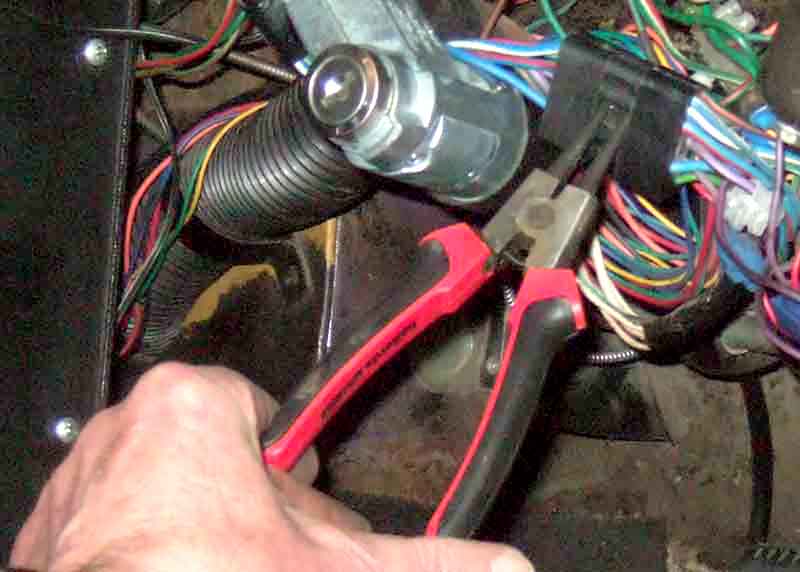 I needed to move the indicator stalk sub-harness out of the way, and unplugging it from the main harness seemed easier than removing the cowl and the switch from the column. However the black rubber moulded plugs and sockets stick together quite well and it was difficult to get a good grip on both halves. Then I had the idea of using external circlip pliers to lever the two halves apart, which took about one second!
 With that out of the way I decided to remove the switch from the back of the old lock, so that vibration etc. from drilling didn't damage it. There is a small screw going downwards at an angle from the drivers side, through the body of the lock and into the switch. A little fiddly to get at, I used a hex drive screwdriver point in a very small ratchet. It's small, don't lose it. With that out I eased the rubber boot off the lock and the switch came away. I then offered up the switch to the new lock - there is a key and key-way that has to be aligned - and checked that with the battery cut-off switch back on the accessories, ignition and cranking all worked. Again you wouldn't want to complete the installation to find it didn't.
 I decided to use a 4 or 5mm drill to start with, even though the threaded hole is about 6 or 7mm, as a smaller drill goes through easier, then its hole acts as a guide for the larger drill. Drilled first one screw then the other with the small then the large drills until going by the depth I reckoned I was just past the join of the two halves that were clamped around the column. By now the lock was moving back and fore slightly round the column, tried levering against the column tube with a pry-bar, but not too hard. Drilled some more until I was sure the large drill was fully past the join, levered again and it fell off. It really didn't take me much more than an hour. I had managed to drill right up the middle of one bolt, and only slightly off to one side of the other. Note that this can only be done with the earlier front-entry locks mounted lower down the column, not the later side entry accessed through the cowl as the bolts are in line with the lock instead of being at right-angles to it.
 Nothing more to do except position the new lock - which is a Lowe and Fletcher just like the original - onto the column, and do up the bolts no more than finger-tight as again I didn't want to complete the installation i.e. fully tighten them until I was sure everything worked. The clamp part has an offset hole, which seems to go to one end of the lock.
 Fitted the switch into the back of the lock and inserted the screw ... and the switch came back out again. Had a couple of goes, but it still wouldn't go into the matching hole in the switch body, and I was beginning to think that the alignment was wrong. But with the screw going in partly from above with all the wiring there it wasn't that easy to hold the switch into the lock with one hand while positioning and turning the screw with the other. So I slackened the lock clamp bolts sufficiently for the lock to hang down which put the screw at a much more convenient horizontal angle, and it went straight in. Again tested the operation of the switch with both keys and all was well, so repositioned the lock and did the bolts up finger tight again. This time I turned the column, keys out, so that the bolt engaged and locked the steering, then waggling the wheel to take the load off the bolt check the keys retracted it, again all good. So final tightening of the bolts, and find the bolt heads are 13mm. They are also at an angle, so whilst one is easily accessible from below, the other is virtually on top of the column. Fortunately I have a set of swivel-head combination metric ratchet-ring spanners, and the 13mm one does the job. Not enough leverage to shear the top one, which I wouldn't attempt with the ratchet ring anyway, and although I could get a standard socket on the lower one I just do them up 'tight' but not too tight. I'll leave them like that for the time being to check all is well, with a view to increasing the tightness later on.
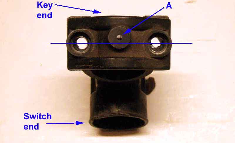
What lies inside: Someone on the MGOC forum mentioned recently that when their key barrel fell out of the lock they drove it for some time using a screwdriver to turn the innards. It struck me that with a steering lock that might have compromised the locking mechanism, and you wouldn't want it to engage when driving along! I'd (of course) still got the faulty lock I replaced as above, and as it wasn't going to be any use for anything else decided to investigate how it worked.
The bottom line is that the barrel assembly turns a plastic cam, which as well as turning the ignition switch proper also lifts the lock out of engagement. So even with no barrel the cam has disengaged the lock once the ignition is on, and although there is no longer a spring detent to prevent the switch coming back by itself, if it does so hopefully it will cut the ignition before the lock engages! Still not a good idea to drive without a barrel though, as it is part of the barrel that positively prevents the lock coming back into engagement until you have withdrawn they key, as described here.
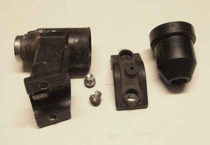
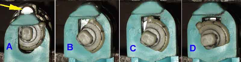
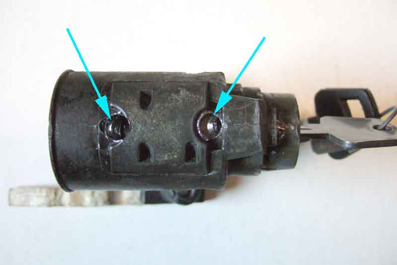 Getting in is tricky. There seems to be a 'lid' over the innards, with a couple of dimples that looked like they might have been filled with something to hold it in place. The metal is very soft so easily drilled, and eventually the lid levered off, leaving a side piece inside the lock. It was only afterwards that I discovered a tiny-tapered pin in the side of the lock that was actually what was holding the lid in place. That needed to be drilled out as well, but as the pin is hard and the metal around it soft eventually I had drilled round it and could pull it out with pliers, and the remaining part of the lid came out.
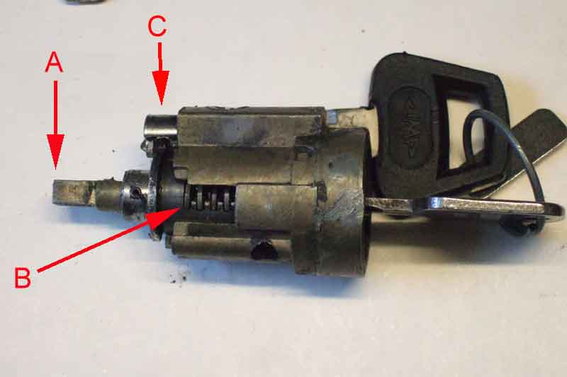 At that point the barrel assembly was moving slightly in the lock body, I couldn't see what was holding it in (the key was inserted), and eventually 'persuaded' it out by tapping with a cold chisel and hammer on a suitable projection. That came out, leaving two plastic components inside - a blue one carrying the metal locking peg that engages with a slot in the column shaft, and a white cam that operates the switch as well as lifting the blue part with the locking peg out of engagement with the steering column as the key is inserted and turned.
 It looked like the blue part should just push out, but the edge of the peg that engages with the column shaft had peened over very slightly which made that part wider than the close-fitting slot, and needed a bit more persuasion. After that the white cam came out as well.
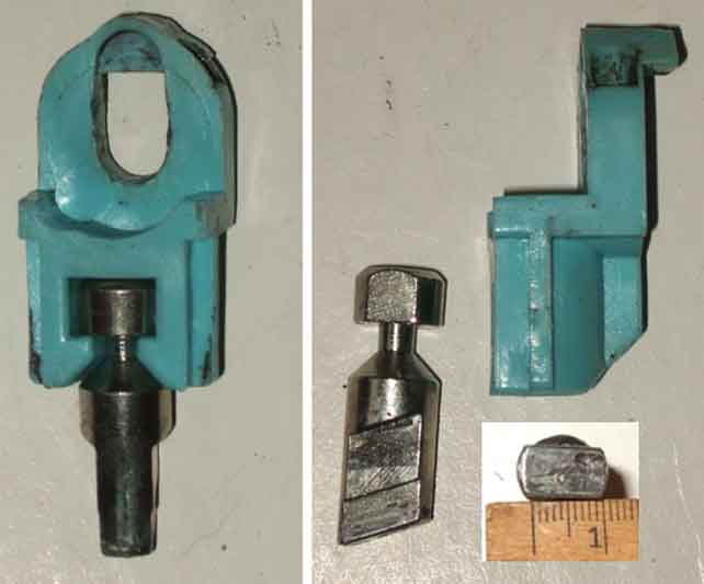
 That allows one so see how it is the white cam that operates both the switch and initially disengages the lock, but there is another more important aspect to keeping the lock disengaged.
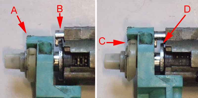 There is a sliding rod on the barrel assembly that is pushed into a recess in the blue part once the key has been inserted and turned and the lock is disengaged, and keeps it disengaged irrespective of what the white cam does after that. When switching off and removing the key it's only when one has gone through the turn-push-turn-pull process on this version of the lock and the key starts coming out of the barrel that this rod is withdrawn from the blue part, and the locking peg drops onto the column shaft or into its recess with a definite click. So the barrel assembly is fundamental to keeping the lock disengaged once the ignition key has been inserted and turned. The main function of the white cam as far as the lock is concerned is just the initial disengagement, the fact it can also keeps the lock disengaged once the switch has been turned if the barrel is removed is only secondary. In fact the sliding rod holds the blue part higher than some parts of the white cam, and whilst the cam will prevent the locking peg fully engaging with the column, without the barrel it does allow it to drop slightly. So depending on how much clearance there is the peg could catch slightly on the shaft slot as the steering is turned.
Indicator/turn Switch and Cowl Positioning August 2015:
 If fitting or replacing a column on chrome bumper cars i.e. without the full energy-absorbing column (i.e. not V8s, and North America may have got them earlier than the UK) the column outer has to be positioned correctly for the indicator/turn switch and cowl. Note that the position of the inner and hence the steering wheel on all cars, and the cancelling striker on Mk1 cars, is determined by the rack being bolted to the front cross-member. The column outer and hence the switch and horn brush and cowl, can slide up and down over the inner, i.e. relative to the steering wheel, and is supported by two U-clamps in brackets, one under the edge of the dash and the other under the heater shelf. To adjust the position of the column outer slacken both these and slide the outer up and down to suit. Correct positioning depends on whether you have a Mk1 or a Mk2:
- On Mk1 models the cancelling striker position is fixed, but there is a small amount of variability in the position of the switch on the outer. Position that centrally within it's range of movement, then clamp the outer such that the switch fingers are correctly aligned with the cancelling striker.
- On Mk2 models the switch goes in a fixed position on the outer, set by a 'lump' on the switch body that sits in a cut-out in the tube, and there is a large range of adjustment in the position of the cancelling striker on the column inner. In this case the column outer position is determined by the relationship between the column cowl and the back of the wheel. The cowl has a flange that should fit neatly inside the back of the wheel, but not so far that the back of the wheel rubs on the base of the flange. With that set correctly, adjust the position of the cancelling striker to suit the position of the switch fingers.
Note that even slackening these clamps may well disturb the column and rack UJ alignment, which should be checked afterwards.
With the later full energy-absorbing column the relationship between inner and outer and hence the switches, striker, horn brush, cowl and steering wheel are all fixed within the column.
"Apparently the lower bush MPB1002 is not only out of stock everywhere but according to Moss they will not be getting any more in as their supplier is out of business. Moss also had numerous complaints and I guess it was due to the poorly fitting part...
"TBH I guess this is to be expected when one considers the ID/OD measurements and I suspect that the aforementioned part was not designed for this job - it was probably a part from some other application from another vehicle."
Brendan also sent dimensional information of the shaft showing how difficult it is to get this bush fitted. He was contemplating breaking the shear pins so he could fit a new bush, then repairing the pins, but as the bushes are no longer available anywhere (it seems) there is no point. I think I would have tried cutting the bush length-wise with a very fine blade, or a hot wire (as Robin Goujah's was), in preference to that. As the OD seems to be bigger than the column outer ID as well, and is difficult to push in, maybe a saw cut would solve both problems and be a snug fit to both. But, as I say, no bushes available.
The original solid and early collapsible columns (CB cars except V8) have upper and lower bushes which wear and can be an MOT failure. The later full energy-absorbing columns (RB cars and all V8s) use a ball-bearing at the top and apparently at the bottom which don't seem to suffer from the same wear problems. As far as the UK goes columns prior to the 1972 model year use upper bush GSV1095. For the lower felt bush columns without steering lock use 17H6565, and those with the lock use 13H569. The intermediate collapsible column from 1972 until the end of chrome bumper production use upper bush MGP1050P and lower bush MPB1002 which is challenging to replace. This has been discussed several times on the MGOC forum and pictures and descriptions, and dealing with failed shear pins, have been pulled together here. Some European markets had column locks on Mk1 cars and so had different columns. North America had different columns - with locks - from the start of Mk2 production. Only from the start of rubber bumper production did all markets get the same energy-absorbing column (Clausager). The remainder of this section relates to this full energy-absorbing column.
Vee's steering wheel has always had a bit of rotational play in the column. At about 6-7mm it is a good bit less than the UK MOT limit of 13mm (and a whole lot less than the 30mm specified in my Toyota Celica manual!) but I still didn't like it, for one thing it rattles over some surfaces. As well as the rotational play the steering lock has never worked in my ownership, so I was wondering if I would be able to do anything about that. The car also had a fuel pump short before my time (as had Bee and two other cars I have worked on, all with fuses now!) so the brown and white were damaged. The white only very slightly there (much worse elsewhere) but the brown has had the bullet connector for the switch harness cut out altogether and the wires spliced together. It's had various electrical bits added before my time also connected to this splice, and when I added a horn relay I added one more to it (at least mine was brown). I'd also had an alarm installed, and the fitter soldered his wires to the 12v and indicator wires on the switch side of the multi-plugs (easier to get at) so with the repairs and additions it was all a bit of a mess round the column - another opportunity.
First job was to remove the upper UJ clamping bolt, so the column shaft can be pulled out leaving the UJ behind. It's worth mentioning here that although my roadster has just a notch on the column shaft, and a groove running all the way round the rack shaft meaning the two shafts can be reassembled in any orientation which seems to be the norm, both the V8 shafts only have notches, so the UJ can only be installed in one position on both shafts - strange, but true. Loosen the other bolt right off while there is still some support from the other shaft, but leave the bolt in position so the UJ stays on the rack shaft, and the nut on the bolt a few threads so the bolt doesn't fall out!
Steering wheel comes off with the usual method. This makes it much easier to get the two halves of the cowl off, especially as the additional screws at the bottom, handily (not!) covered by the dashboard, were removed and not refitted by a PO. This is why the book says to remove the column complete with cowl and switches, which would be right pain if all you wanted to do was adjust the horn brush! In fact the book says to remove the column complete with the steering wheel as well as the cowls and switches, which is stupid if you subsequently need to remove the wheel. Unscrewed the column switches and left them dangling. At that time I couldn't see how to remove the ignition switch from the steering lock so had to cut the splice in the brown, and the alarm wire. The other ignition switch wires are on bullets, rather than a multi-plug like the column switches.
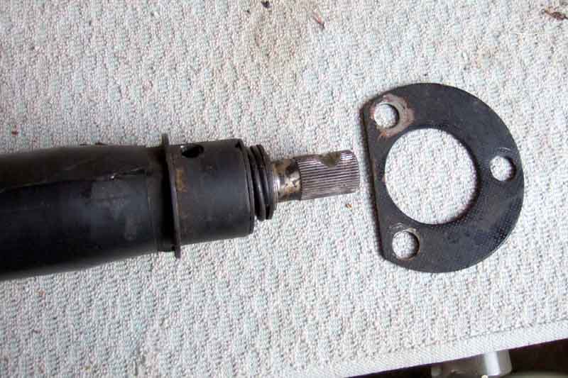 When it came to undoing the three toe-board bolts they were only finger-tight, and when I got them all out (the top one is tricky, needing two 3/8" wobble extensions) the plate wasn't attached to the column anyway, not just loose but flopping all over the place and falling right off when I finally removed the column! The hole in the plate is quite a bit bigger than the end of the outer tube it fits over, so there is no way it can align the bottom of the column to the UJ, which some say it does, but more of that later, the upshot is that simply slackening the three toe-board bolts should be all that is required to pull the column out, and leave the plate and rubber seal in-situ - much easier than completely removing all three bolts.
 When I undid the upper bolts and started trying to pull the column out I could tell the lower half of the inner was staying where it was, even though I had removed the UJ bolt. I realised I would have to lever it out from inside the engine compartment so would need to support the wheel end of the column on some cord while I did so - of course no cord within reach! So I tried to put one of the upper bolts back in but even though the column bracket is slotted it was too far back to get any bolts in. Took quite a bit of pressure pushing the column down towards the toe-board against what seemed like spring pressure to get one in. When I finally got the column out of the car I found I could pull the bottom half completely out as the shear pins (actually injection moulded plastic) had done just that - hence the rotational play.
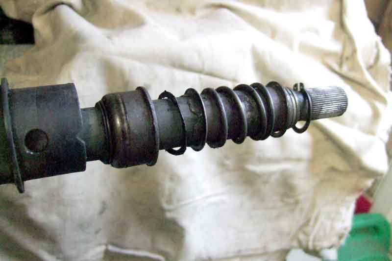
There is a spring at the bottom of the lower half, pressing back against the lower bush in the outer, and forwards against a circlip on the inner shaft, which is effectively trying to push the shaft out of the bottom of the outer all the time. Ordinarily the shear pins mean it is pulling on the upper half of the shaft, and the upper bearing on that is pulled down into the upper end of the column, as well as being retained by another circlip. That's why I had trouble temporarily getting an upper bolt back in - I was having to compress that spring by pushing the column towards the toe-board far enough to get an upper bolt in, and it's quite a hefty spring! As to when and how the pins had sheared, I don't know.
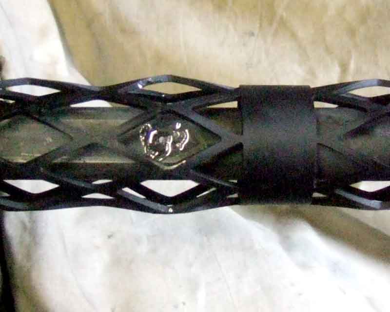
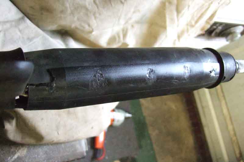 With the column finally out there is a plastic sleeve wrapped round the lower half of the column, covering the collapsible mesh section. Glued or heat-bonded with five blobs down the edge I cut through the bonds with a sharp knife, and can now see the shaft through the mesh. With the lower half of the shaft pulled out I can see the remains of the injection moulding process in two places on the upper/inner half of the shaft, and four 'nubs' of plastic sticking out of four holes (two each side) in the lower/outer part. I also find that with the lower half of the shaft out, the free end of the upper half is free to flap about inside, and in some positions the steering lock (key out) is catching, but when held centrally it is free. So I wonder if it has been attacked by thieves before my time (apparently if you don't turn the wheel to engage the lock when you have removed the key, they can wrench the wheel round and as the locking pin drops into the hole the momentum snaps it off). But later on when I have been working on the column I find the lock engaging with both parts fitted, and has to be released with the key, so maybe the locking pin is whole but just sticky. I do find the ignition switch slathered in oil, maybe squirted in to try and get the lock working. Never use oil or grease in a lock, only graphite powder.
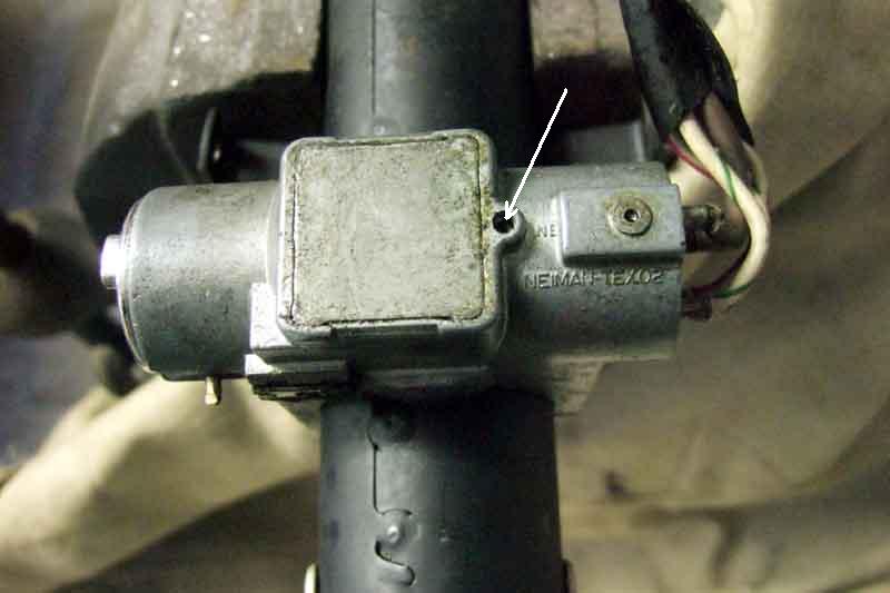 With the column on the bench I espy a tiny grub-screw under the switch, which when unscrewed to flush with the lock housing allows the switch to be withdrawn. If you are going to be leave the switch out for any length of time screw this back in to prevent it falling out and getting lost. One oddity with the ignition switch is that with the various work that has been done on the wiring there is black insulation tape wrapped round it, which I have to remove to expose the alarm wire soldered to the brown, and I find a purple/pink wire. Now this is only used on North American spec cars, for the anti-runon valve. So whether the car has had an American column and/or switch at some time, or whether the manufacturers use a standard tail and just cut the unused wires off (there is no spare contact on the switch for this wire) I don't know. Update: The purple/pink is standard on all switches for this type of column i.e. all RB cars but there is no corresponding wire in the harness-side of the UK multi-plug.
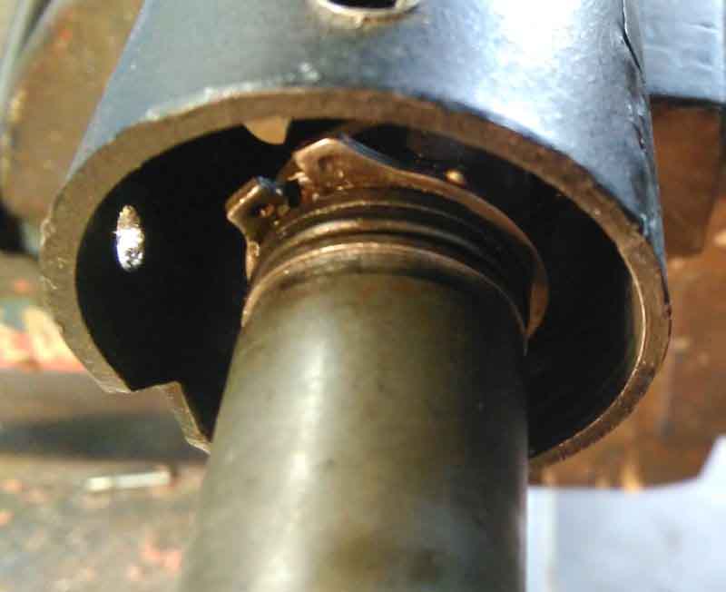
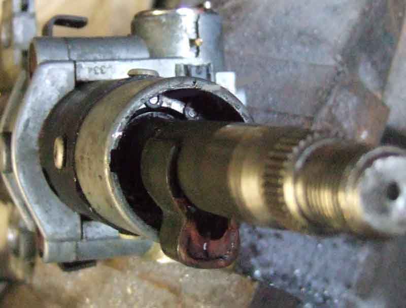 I don't want to cut the lock assembly off the column (the shear bolts have sheared off), so wonder if I can remove the upper half of the shaft from the outer. This may allow me to see what is happening with the column lock, and possibly free it up if it isn't broken. I espy a circlip quite deep inside top of the outer, and manage to get that out of its slot. My angled internal circlip pliers won't go in that far, but by using one leg of a straight external set to lift up one end, I can then get one leg of my angled internal pair in that, and shift the other end of the circlip with one leg of my external pair. The shaft with it's bearing can then move up and down a couple of inches, but something is stopping it coming out altogether. There is an alloy casting at the top of the tube, held on with three large pop-rivets. I'm guessing I could have drilled those out, and the casting would have come out allowing the upper bush and shaft out, but don't have any replacements that size so stop short of drilling them out. Oh well, it's not had a steering lock for my 16 years, I doubt it matters now. December 2014: It was only after replacing the steering lock on Bee that I suddenly thought that it was probably the steering lock that was holding the shaft in the outer, if I had inserted and turned the key it might have come free. However when responding to a BBS request about stripping these columns I mentioned that, but he had the same problem and didn't even have his lock fitted. end of update Incidentally, the fact that the upper part of the shaft is retained in the outer this way, means that hammering on the end of the column to free the steering wheel, especially if your knees are braced behind the wheel, means that you are highly unlikely to break the shear pins, much less collapse the column. It's more likely to be a problem at the other end if you have to hammer or lever the UJ back on if the splines are stiff, but even then there is a strong spring pressing the lower shaft downwards, the same principle as bracing your knees behind the wheel.
December 2017: John Bilham had to go through a similar process when installing PAS but was more persistent than I was. He writes:
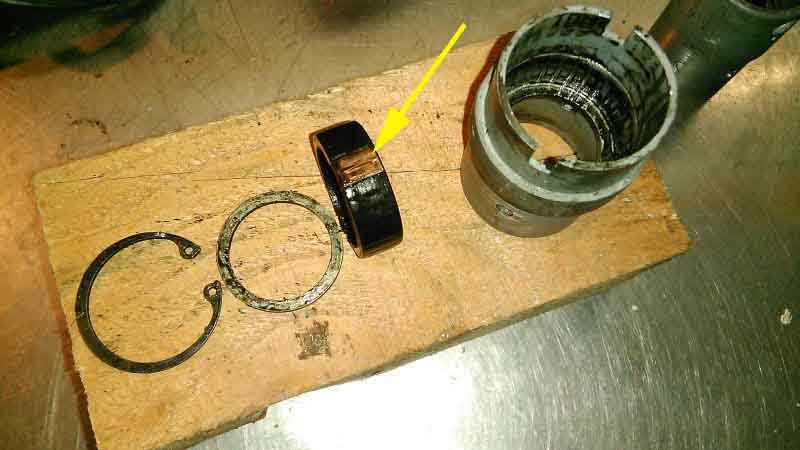
I decided to remove 'my' bearing carrier first, so drilled the heads off the three rivets hoping to just slide it off the column. That didn't work, but on closer inspection I noticed that in addition to the large inside circlip which retains the bearing (I wasn't going to remove the bearing itself), there was another small outside one sitting on the shaft in front of the inner ring of the bearing. When I removed this the carrier and bearing slid off. Looking at the exposed shaft, there is the slot for the circlip, then a rubber oil seal, similar to that on a valve stem, that the bearing sits on, and then what looks like another slot, although it's difficult to see.
 When I drilled the heads off the rivets on the other, supplied, column, the carrier moved a few mm but wouldn't slide off. This column has the large inside bearing-retaining circlip but not the outside one on the shaft. I then realised the heads had come off but the rest of the rivets had remained in place and these were obviously catching on something hidden on the column. They couldn't have been very tight because they just rotated with the drill bit, and were still long enough to almost touch the shaft. Took enough off them to allow them to fall out and the bearing casing just slid off. This revealed an outside circlip similar to mine, but this was sitting behind the bearing (which was what the remains of the rivets were snagging on) but with a similar oil seal in front of it.
 Further investigation by John (more than he needed to do for installing his PAS for which I'm grateful) dismantled the bearing housing into housing, bearing, shim and circlip and revealed all, click the thumbnail.
Subsequently John writes:
But back to the repair ...
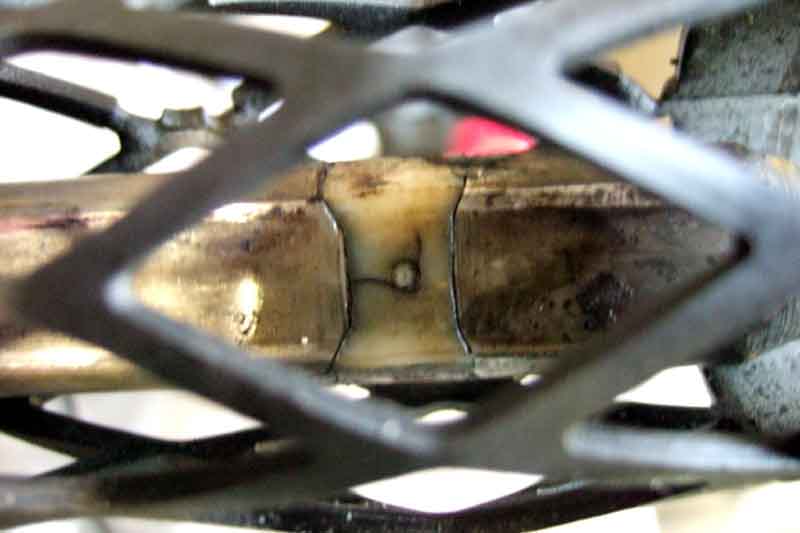 ... and to somehow join the two halves of the inner shaft back together. They are sort of rectangular section where they slot together (to guarantee still being able to steer even if the pins shear!), which has to have some clearance of course. There are holes in the outer, and a 'waisted' section under each hole in the inner. Plastic/nylon is injected through the hole on one side, filling the waisted sections and the gap between the two halves of the shaft, and exits from the hole on the other side. The broken ends of the shear pins came out of the lower half of the shaft easily enough, and the moulded inserts can be eased off the upper half. Whether the moulding around the waisted section always compresses over time to give some play, or whether mine only had the play because the pins had sheared I don't know. I decide to leave the remains of the injection moulding in place as removing them could introduce even more play, but need to pin the two halves of the shaft together. I can see where the pins have sheared off, so mark this position on the outer casing, then slide the lower half of the shaft over the upper until the holes in the outer line up with my marks, i.e. they are over the middle of the waisted sections. I use the holes in the outer as a guide and drill through the inner, so I can insert a pin all the way through.
 I decide to slather some Araldite under and round the two halves of the nylon insert, and inside the holes in both upper and lower sections, so that when the lower half is pushed back over the upper that, and a pin through the hole, should hold the two halves together and take out the rotation play between them. Some people have said they used a hot-glue gun to replace the nylon shear-pins, but as described above there is a strong spring trying to pull the lower half of the inner out of the bottom of the outer, but the upper half of the inner is retained by a bearing at the top of the outer, so the force of the spring is being exerted on the repair. I use a metal pin in each position, not being bothered about changing the collapsible characteristics after all these years, you do this drilling and pinning at your own risk! Note that the two halves of the shaft will fit together in two positions 180 degrees out. Oddly both my rack and column shafts have notches for the UJ bolts rather than one shaft having a notch and the other a groove all the way round, so my column and rack shafts will only connect in one position, which means if I reassemble the column shaft 180 degrees out the indicator cancelling cam will end up in the wrong position (as it would if you had a shaft with a groove, match-marked it, and reassembled to that). No big deal as it is only a friction fit on the shaft and can be slid round, but nicer to get things correct in the first place.
Leave that to set a bit and start tidying up the wiring, which basically consists of putting bullets back on the ends of the original brown wires in the harness and ignition switch tail. However as I have no less than four additional circuits that need to connect back to this brown, rather than have a veritable daisy-chain of bullet connectors I splice three of them together with one bullet (two have in-line fuses close by and the third connects to a relay with a spade also close by, so easy enough to isolate each of them for diagnostics) and use the fourth hole for the alarm wire as that goes across the car to the alarm unit in a mini-harness. Turn the power back on and check everything electrical still works, even though the switches are still dangling, and the horn button is removed with the wheel. It's while doing this I discover a thick washer on the carpet, same size as the three that are still on the upper bolts - wonder where that came from...
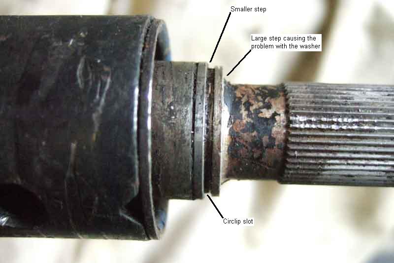 I then start thinking about the pesky bottom spring and circlip. As I said it is pretty hefty, and just with hand pressure I can't get it compressed far enough to get the circlip on - nowhere near. I'm thinking I'm going to have to lever it down with something, but it will have to be pretty thin as there is going to be very little room to fit the circlip in its slot. I find some flanged plates about 8" by 2" from my BT days some 30 years ago (!) which may be strong enough. I cut a hole in this plate, which just fits over the end of the part of the shaft the circlip fits into, which is narrower than the part that the spring and a washer fits over. As I've only got two hands I stand the steering wheel end of the column on a suitable block of wood, put one end of my plate under the edge of my bench, and press down on the other end of the plate with a hand. It's compressing OK, but the problem is the washer is catching on the shoulder of the shaft, and as I'm levering rather than a straight press it is proving impossible to keep this washer aligned with the larger diameter it is supposed to go over while I'm levering. Go and gaze at my various bits again, and see an old box plug spanner which looks interesting. I'm amazed to discover this just fits over the narrower part of the shaft, and also just fits inside the washer and spring, so perfect for aligning the washer with the thicker part of the shaft! So now I put the box plug spanner through my plate, put the washer and spring on the end of the box plug spanner, and slide that lot over the end of the shaft. Now levering on the plate pushes everything over the larger diameter, and I remove the box plug spanner to reveal the circlip slot - so far so good. However it's still a bit of a fiddle picking up and manoeuvring the circlip one-handed while pressing down on my lever with the other, so I devise a system of string and a tommy bar (from the same plug spanner!) to pull the plate back and compress the spring while the column is clamped in the vice, and I have two hands to fit the circlip. Easy-peasy? - er no. Of course I have forgotten that the circlip is now trapping the plate! But filing the hole in the plate out to a 'keyhole' shape slightly larger than the circlip, but still smaller most of the way round than the washer, I can now fit the circlip into its slot, and lift the plate off over it. Feel thoroughly pleased with my ingenuity, and life-long policy of never throwing anything away - "If you haven't found a use for something yet, you haven't kept it long enough". In fact I have had a major clear out of the garage recently as we are planning to move house this year, but obviously kept enough of the right bits! Finally reattach the plastic cover over the mesh section of the outer, taping it up with masking tape while the adhesive dries.
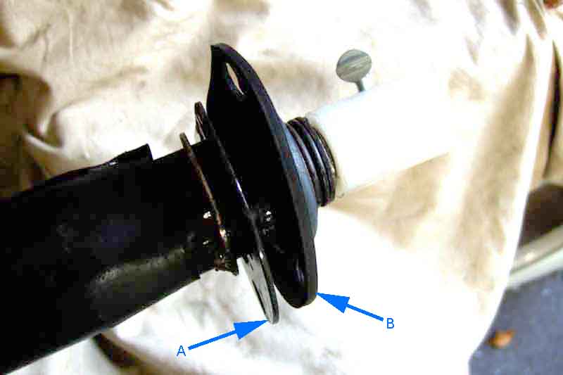 And now for the refitting and alignment! There is a small ring welded to the outer tube, which the loose plate butts up against, so I wondered if it should be attached to that, although there was no sign it had been. However that puts the plate about 1/2" away from the toe-board which obviously isn't right. And with this column unlike earlier types the inner is fixed in the outer and cannot move up and down, only rotate, so the whole column has to be able to move up and down to get the right distance from the rack shaft so the UJ bolts will fit through the cut-outs in the shafts. Although some have said this bottom plate is part of the alignment, pushing the bottom of the column into the correct position, I've come to the conclusion it is nothing more than a body seal against water, noise and fumes. Two people have confirmed that theirs is also loose and detachable (making it odd that Moss Europe at least show it as part of the column), and another has said the same and that he has a rubber bush, that slides onto the lower part of the column outer, and makes a snug fit to the hole in the plate.
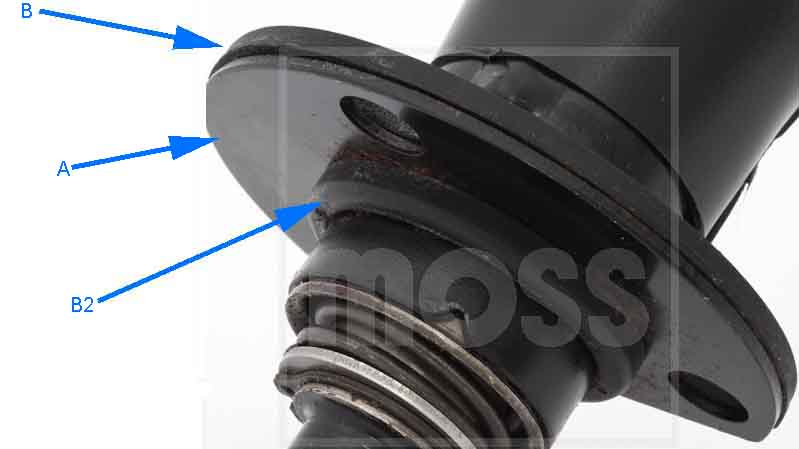 August 2016: That makes more sense, and Moss Europe have a closeup of this plate and the rubber seal, where part of the seal pushes through the hole in the plate. However they show the seal having been slid onto the column first, then the plate. As there are bolts that go through the plate, seal and toe-board one would expect the seal to be sandwiched between the plate and the toe-board, i.e. the plate pushed on first, and the seal after it. When the column and rack-shaft have been correctly aligned over-size holes in the plate and/or toe-board should allow bolts to be pushed through and tightened to provide clamping, but not alignment. In practical terms it was easier to loosely bolt the plate and seal to the toe-board first, then push the end of the column through the hole, rather than slide the plate and seal onto the column, put it in position with at least one upper bolt, then try and get the plate bolts in - the top one in particular is a real fiddle but all are more difficult that way. Now the seal and plate are positioned laterally and vertically by the column, and when the plate bolts are tightened it compresses the rubber such that it expands sideways and seals to the column shaft, as well as being bolted down to the toe-board, to prevent the ingress of water.
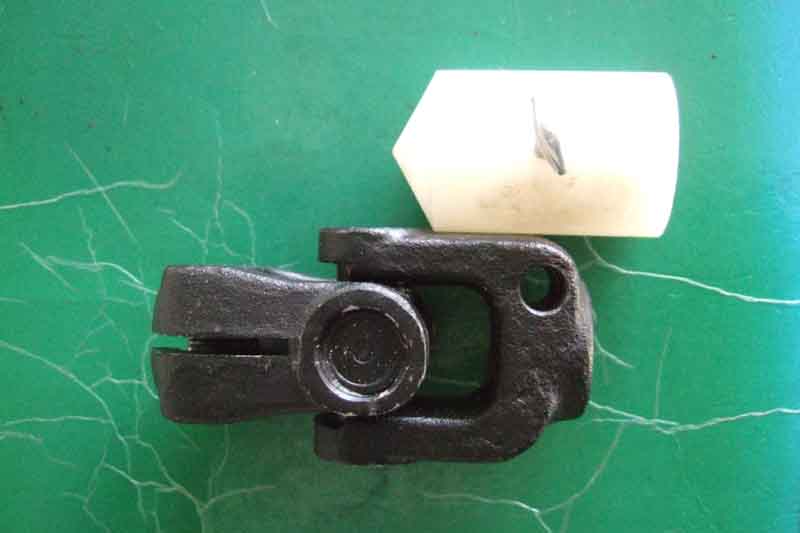 Another thing concerns the alignment gauges. The book says to remove the rack, even when it is the column that is being refitted. You do have to remove the rack later on, but there is no point doing it now only to have to refit it, then remove and refit it a second time later on. If using the Moss gauges these have two tapped holes depending on which rack and column they are used for. Compare the gauge to the UJ, position the tip in line with the centre of the UJ, and see which hole in the gauge lines up with the clamp bolt hole in the UJ, and put the clamp screws in those holes. Note that each part of the Moss gauge seems to be a couple of milli-metres shorter than the rubber bumper UJ (not so the chrome bumper), so bear this in mind when doing the alignment i.e. leave a couple of mil between the points or you may not be able to get both UJ clamp bolts in right at the end (alternatively, fit the UJ first, nip up the column bolts to get the correct in and out adjustment, then pull the rack forwards to replace the UJ with the gauges and note the gap between the tips, if any. When you have corrected the column and rack shimming for horizontal and vertical alignment make sure you end up with that same in and out gap). Apart from that when refitting a column it's easier to fit the alignment gauges first, minus the screw in the column piece. Then fit the column loosely, the alignment gauge easily goes through the toe-board plate and seal, and then fit the screw to the column half of the gauge. This is a bit fiddly being recessed into the toe-board 'cup' as it is but can be done. It would be easier with a knurled bolt, or even a hex bolt, or if the screw could be pushed in to the hole a little way before the threads started. Note that the screws must screw into the bottom of the cut-out in the shafts, not onto the splined portion. My Haynes is completely wrong here, by saying the rack and column should be fitted before installing the alignment gauges. This simply cannot be done, the two have to be moved apart a couple of inches to get the gauges onto the shaft, and off again to refit the UJ. With the gauges on adjust the column position and the shims as above to get the correct alignment. However my Leyland Workshop Manual also has a major error, in that it tells you "Slacken the screw on the column point gauge and slide the gauge down until the points of both gauges are on the same plane but not overlapping". The whole point of the gauge screws with this column is that they must screw into the cut-outs in the shafts, and the whole column must be slid up and down to get the correct in and out position. Unless you do this it is highly likely that you will not be able to get the second UJ clamping bolt inserted, the cut-out in the shaft not lining up with the hole in the UJ. This isn't the case with earlier columns, where the whole inner shaft is free to slide up and down inside the outer, with those the shaft will automatically take up the correct position. I repeat, with this later energy-absorbing column you can only adjust the in and out position of the inner, and hence get the cut-out in the correct place for the UJ, by moving the whole column on its upper bolts (which is also why the toe-plate must be able to slide up and down on the column outer).
Additionally at the end of the process i.e. with the gauges replaced by the UJ, it tells you tighten the two upper bolts, then measure the gap at the third bolt, and fit shims accordingly. This makes no sense to me, as the gauge of the correct size would have to be gripped by almost the same tension as the final shims which is 12-17 ft lb as you were sliding it in and out. Better to align, fitting shims as required to the third bolt and tightening all three to get the correct alignment while the gauges are still on the shafts. More long-winded certainly, but it seems more accurate to me. The two upper column bolts do not allow the column to 'rock' on them when tightened, so unless the shimming required on the third bolt is negligible to nothing then there must be some sideways pressure on the UJ and hence the rack pinion bearing. If you shim the column to that final position, then the two shafts will not be accurately aligned. When the column and rack shafts are correctly aligned with the gauges, only then pull the rack forwards to remove the gauges, fit the UJ, and refit the rack. Unlike the column, the rack (with any shims) should always go back in the same position. Whereas if you are only fitting shims to the third column bolt and fully tightening that after the UJ is installed, you could be affecting the vertical alignment, and indeed would have to lever the bottom of the column downwards in order to get the shims inserted. This is why it makes more sense to fit the gauges before installing the column, leaving the rack where it is until the very end of the process, only then pulling the rack forwards to remove the gauges and refit the UJ. Note that if you raise the front wheels off the ground you only have to remove the four rack bolts, leaving the track-rod ends attached to the steering arms. As you pull the rack forwards a few inches to allow you to remove the gauges and fit the UJ, the wheels will simply go 'pigeon-toed' i.e. turn in towards each other.
Refit rack bolts, tighten UJ clamp bolts, refit switches. Check all the electrics again, which involves putting the key in the ignition, and immediately sense that it is now closer to the bottom of the dashboard than it was before. I now realise what that odd thick washer was - it must have been between the column and body brackets on the right-hand bolt which would space that side down a bit - buggah! To fit it now would involve realigning the column. Consult the workshop manual to find something I missed before, that there should be such a spacer on all three upper column bolts! Indeed six shown in the Leyland Parts Catalogue, but only three in online parts lists. However the manual talks in terms of "if the packing washers are mislaid" so it is probably no big deal, and I can live with it until I next have to remove rack or column. Refit the column cowls before the steering wheel as it is easier, and if the lower cowl screws (covered by the edge of the dashboard) were fitted before don't bother refitting them, they just aren't needed. If you haven't upset the positioning of the indicator cancelling cam, and it was correct to begin with (cam pointing at the switch when straight-ahead), then loosely refit the steering wheel to turn the shaft to the straight-ahead position, then refit the wheel fully. Otherwise fit it with the nut not fully tightened, take it to a quiet straight road close by (not 10 miles away!), and adjust as required. Take your socket etc. with you so as to fully tighten it before driving back, so you can take the scenic route and enjoy getting your car back on the road again. The rattle-free steering really is an improvement.
Steering Column Universal Joint Added August 2010
Replacement
Alignment
November 23: As far as I was aware CB cars (including V8) always used UJs that could be dismantled and just the spider, cups and needle bearings replaced with a kit originally 17H3873 now GUJ200. But most suppliers currently show a one-piece assembly with non-replaceable bearings - AHH6000. That was always the part number for the complete assembly in the Leyland Parts Catalogue, so I tend to think manufacturers have adopted that number for a one-piece alternative. However Moss for example quotes AHH6000 as 'OE' and AHH6000Z as 'after-market', showing the one-piece in both cases with the OE as 'NCA', but unless the factory did start using a one-piece in the final few months of CB production that's probably a stock photo. RB cars (including V8) always had a one-piece originally 575732 now listed as GLR3084 or NRC7704.
Whilst the one-piece does avoid the fiddle of getting the spider and cups out of the yokes, and refitting, they are about seven-times the price of the repair kit for the repairable version. OTOH I replaced Bee's four times in 23 years and picked up slight play in the current one in 2018. Although not a source of MOT problems (on previous occasions it's been a failure) there have been advisories of wear in the rack for about three years, including a replacement only a few months old. So I'm wondering if it is the UJ they are picking up and have ordered another kit to replace it yet again (which didn't help). Ironically, despite doing double the mileage (with me) and several years of that with intractable steering wheel vibration Vee is still on the same UJ she came to me with! Because of the vibration I expected problems with that UJ, so bought a new one ready for if and when I got the vibration fixed, which I did eventually but the UJ still shows no play at all so it sits 'on the shelf'.
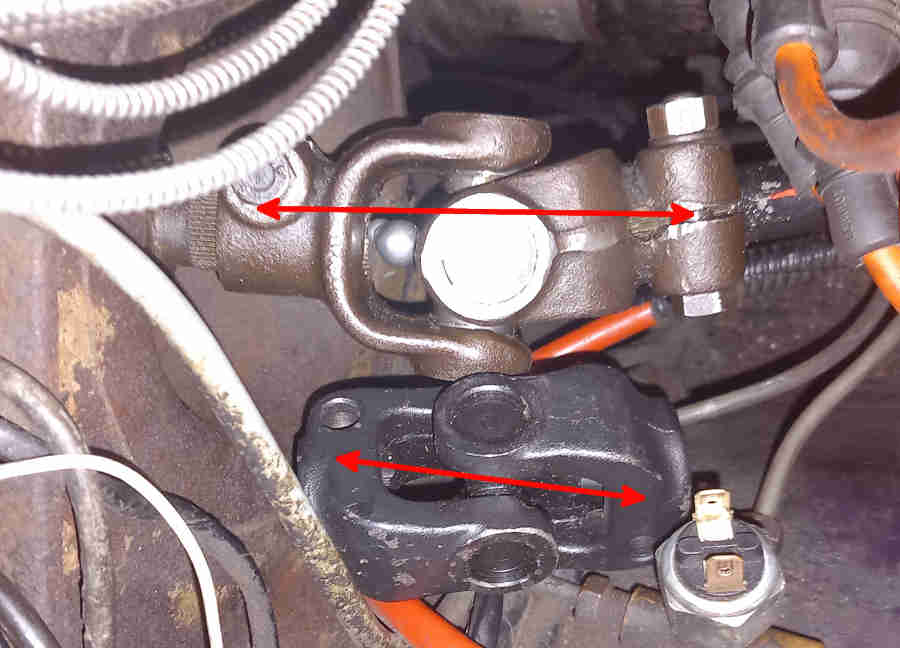 CB UJs are longer than RB - about 3" from clamp-bolt to clamp bolt whereas RB are about 2.5", RB are also recessed further into the bulkhead than CB, possibly because of a repositioning of the rack on the crossmember and the shaft passing through the chassis bracket for the engine mount. The CB V8 has the same crossmember as all RB cars but a unique rack and steering column with the CB UJ, with the same rack and steering wheel positions for CB and RB I don't know why it didn't have the same column, rack and UJ right through. Again I don't know if it applies to all rubber bumper cars, or just to V8s, but there is an oddity in the splined shafts that go in the UJ. On the CB roadster the column shaft has a notch for the clamp bolt meaning it can only go in the UJ in one rotational position, whereas the rack shaft has a groove all the way round meaning it can go in the UJ in any rotational position. This means the two shafts can be assembled in as many different relative positions as there are splines on the shafts. But on the V8 both column and rack shafts only have the notch which means the two shafts can only ever be connected in one relative orientation.
 Both my UJs, and images of others for sale look the same, have the same distance from the centre of the spider to each clamp-bolt, which means the UJ can be fitted either way round. But this picture dating to 2017 which seems to be of a 65 MGB in Poland, so probably LHD, has the centre of the spider offset towards one clamp bolt by a significant difference. So much so that it looks like either it has been assembled from one CB yoke and one RB, or is for a completely different vehicle altogether. There is no indication in the Parts Catalogue that an LHD UJ differed from an RHD. The centre-line of the two shafts crosses at a certain point in space, and that is where the centre of the UJ must be for correct alignment. Not only is this UJ going to position the column in a different place to how it would otherwise be with a symetrical UJ, but the centre of the spider will be in a significantly different point in space depending on which way round it is fitted to the shafts. The former situation is possible on the early and mid era columns as the outer tube can slide in the mounting brackets, and the position of the outer in those brackets positions the cowl to the steering wheel.
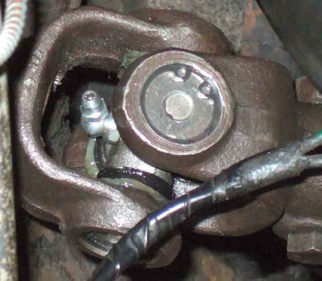 Bee's didn't originally, and probably the first one or two replacements, but since then and currently they have a grease nipple (not that annual greasing has prevented wear!). One piece UJs are sealed for life. The supplied nipple is an angled one, and is in two parts i.e. a straight nipple screwing into an angled base. With the steering turned to the appropriate position the nipple is pointing straight up, so easy to get a 6mm socket on to unscrew it from its base, which I had previously screwed in to the tapered threads so as to position the nipple between the two yokes. I have the idea of making an adapter by finding a bolt that screws into the nipple base, drilling a hole through that, cutting the head off, then drilling and tapping a for straight standard nipple to screw in to the bolt. The first brass bolt I find in my box of bits screws into the nipple base. It's a bit loose as the threads aren't the same but should be OK as I only intend to use it for greasing, replacing it with the under-sized nipple between services. The bolt has a 3BA thread, so I drill and tap the standard-sized nipple right the way through (it doesn't need a ball and spring to keep dirt out as it isn't staying on the car) making it easier to clear out swarf afterwards, and I pump a little grease through the assembled nipple and adapter stud just to make sure they are clean. Unscrew the under-sized nipple, screw in my adapter, pump grease gently until some issues from the cups, and none comes from where the adapter screws into the nipple base, which I reckon is a pretty good result! Finally unscrew the adapter and refit the under-sized nipple (which still has its ball and spring to keep dirt out of course). All I have to do now it put the adapter in a small poly bag and keep it somewhere I can find it at the next service ...
This time was more of a struggle than I remember on the previous occasions. It needed the cups pressed through with double sockets (small one on the back of one cup, large one round the other one being pressed out) in a large vice as far as they would go i.e. until the spider is pressed up against the inside face of the spider, then the few mm of the cup that protruded gripped tightly in the vice while I twisted the yoke back and fore lifting all the time - not easy. Then the spider and the other cup has to be pressed the other way through the yoke, again with double sockets, the small one this time pressing on the end of the spider, again to expose a few mm of cup, remove the spider, grip the cup in a vice and twist out as before.
Reassembly also needs a large vice - if there is a grease nipple fit this first. Get the first cup started in one side of the yoke - no sockets needed but make sure it is 'square' to the hole before applying loads of force. Then once part-way in feed one end of the spider into the 'empty' side of the yoke and swivel the other end of the spider over the partially fitted cup and insert it being careful not to dislodge any needles, but they should be held in position with pre-applied grease. Then fit the other cup, again no sockets and being careful it is 'square', and especially careful that both ends of the spider are fitted into the cup without dislodging any needles. Once the spider is in both cups clamp up to put both cup bases flush with the yoke. Then another small socket on the back of each cup in turn to press it in just enough to fit the circlips.
Circlips were another issue - the existing ones seemed too big for the hole, circlip pliers wouldn't lift them straight out so I had to use a combination of pliers and a very small screwdriver to lift one end free of the hole then pull on that to get the rest out. By contrast if anything the new circlips are a bit smaller than I would like, floating in the groove much more, with only a small overlap when pushed to each extremity. Next time will be a one-piece!
October 2018: Returning from The Beacons Run in Bee 'at speed' I'm aware of a slight vibration from the steering wheel - but nowhere near as bad as when the V8 wheels were unbalanced - and investigating shows there is slop in the UJ - again, after six years and just 10k, and despite this one having a grease-nipple I've lubricated each year, so yet another replacement needed. By contrast the different design on Vee - despite 100k with me quite a few of which with significant wheel imbalance and wobble - is the one that came with the car. Replacements can be very variable in price - anything from �8 to �16 from the usual suspects plus eBay. Delivery can be anything from �0 to �11 with some sources having a low item price but high delivery cost, so you need to look at the total price when making a decision. Before replacing that (the fourth replacement!) I got the front wheel balance checked.
August 2012: Bee had advisories on both track-rod ends this year. Having a quick look the boots had split on both, and the pin on one was loose in the body so I'm surprised it wasn't a fail. But while checking those I became aware of slop in the column UJ (again!) and that is usually a fail. This will be the third replacement, the first (July 1997) failing at the next MOT as the cups were loose in the yokes, but I got a 50% refund on that one against a replacement. The second replacement (July 1998) lasted about eight years and 20k, this one (bought June 2006) six years and 12k. Thinking it could be column and rack alignment, my previous attempts being done with wire pointers as above, and having recently found Moss UK have the alignment gauges, I get the UJ, track-rod ends and gauges from Moss.
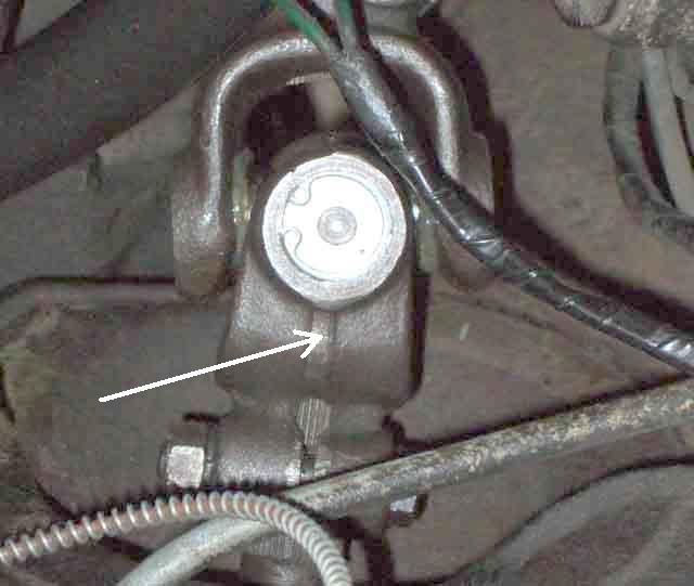 The UJ change was a fairly straightforward operation - remove the four rack bolts, pull it forwards about an inch or so (the wheels will toe in) and with the column shaft pulled back (early collapsible column inners move in and out a couple of inches) there is enough room to get the UJ assembly off the shafts. Circlips removed and tapping the yokes knocks the cups out, but the new ones need the big vice to press them in, so no problems of them being loose next year! I then go to grease it using the supplied nipple and find it is smaller than standard, so my grease gun doesn't fit. The tapping in the UJ body is also smaller than normal so a standard nipple won't fit that either. Eventually I sort out a solution but in the meantime get on with checking the alignment of the column and rack shafts.
Alignment: July 2008
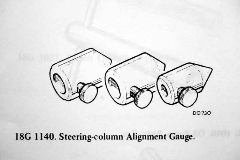 The objective is to get the centre-line of the rack shaft crossing the centre-line of the column shaft at the exact centre of the UJ. It is achieved by shims between the four rack to cross-member mounting points, together with positioning of the steering column within the movement of its mounting bolts. It is necessary because the rack and column shafts sit at different angles in both the vertical and horizontal planes, as well as manufacturing tolerances in the bodyshell and crossmember. The factory used this tool (click thumbnail), note that the different bores were probably because it was a standard tool across a range of BL vehicles, although there are different lengths of column and rack shafts of which more later. Highly unlikely to be available now (until replicas available from Moss), so how do we replicate it? Personally I wrapped some stiff wire around the end of each shaft, with the tip of each wire at a point in space equal to where the centre of the UJ would be when fitted to that shaft. You can get the tip exactly on the centre line by rotating each shaft in turn, if you get any wobble of the tip it isn't aligned, so tweak it until it is stable. Then it is a matter of fitting shims and adjusting the column as required to get the two tips just touching, which could be quite a long process of trial and error. Others have said they used blobs of Blu-Tak or similar. The problem with both of these is that it is very easy to knock the tip of the wire or Blu-Tak off-centre as well as length. Some have said they loosely fit the rack, connect up the UJ, then measure the gaps between the rack casing and the crossmember and fit shims accordingly. Personally I don't think that is good enough on its own as the weight of the rack will be hanging on the UJ to some extent, although it is probably good enough to get a starting point for shims, and trial and error with pointers after that for fine adjustment. Update January 2010: Even worse is a method I've seen where someone turns the steering wheel back and fore while someone else tightens up each rack bolt bit by bit, till the steering wheel binds, then that bolt is slackened a bit, a section snipped out of a washer so it can be slid on the bolt, and that bolt tightened. That is so crude, the UJ will surely start binding way before you can feel any resistance at the steering wheel, hence still be binding when it is backed off a bit and the washer tightened. Besides which the washers that were shown were way thicker than any shim I have seen. Definitely from the "If it isn't bodged it won't work" school of engineering.
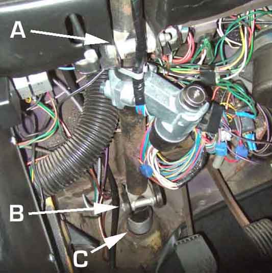 The early and intermediate columns (all Mk1 cars, and non-North American chrome bumper cars except V8s) had a different mounting arrangement to the final full energy-absorbing column. The early and intermediate columns have two sets of brackets under the dash, the one at the steering wheel end offers up and down movement whilst the one at the toe-board end offers up and down movement between column and bracket and side to side movement between bracket and heater shelf.
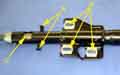 The later energy absorbing column has one bracket under the dash with three bolts, and the bottom of the outer tube has a loose plate with three bolts screwing it into the firewall. It's been said that this bottom plate and its bolts are to align the column but that is not the case, they simply clamp the loose plate and a gasket to the toe-board and are solely to seal the body aperture against water, noise and fumes ingress. The three upper bolts go into caged nuts so offer side to side adjustment, and spacers between the column and body brackets offer up and down adjustment. With those three bolts tightened the column is held rigidly so there is no scope for adjustment at the toe-board plate, those three bolts are only tightened when UJ alignment has been achieved.
With the early and mid-era columns if you remove the column or slacken its clamp bolts even if you haven't altered the rack you will need to recheck the alignment before tightening the column clamp bolts. For these columns the inner shafts are free to slide up and down and will automatically take up the correct position when the UJ is fitted. This is not the case for the later energy-absorbing column where the inner is fixed in relation to the outer. As long as you note where any spacers were fitted to the column mounting point and replace them as found to set the vertical positioning you can remove and replace the column and the UJ will position it correctly both fore and aft and horizontally, and you will have to insert both UJ clamp bolts and tighten the rack bolts before tightening the column bolts. That does leave some scope for side to side misalignment because of the caged nuts in the body bracket so it is preferable to pull the rack forward to remove the gauges and fit the UJ.
As far as using gauges goes my Haynes says that the rack and column should be fitted before installing the alignment gauges. That can be done with the early and mid-era columns (my CB roadster) as the column inner can be slid up the outer to get enough space to fit and remove the (Moss at least) gauges. With the early column the inner can be slid back far enough to enable the UJ to be fitted and removed as well, but with the mid-era column with steering lock the inner does not slide back far enough for the UJ, only the gauges. With the later full energy-absorbing column (my V8) you can't fit or remove either gauges or UJ without moving either the column back or the rack forwards as the inner cannot be moved relative to the outer.
The rack gauge must be positioned correctly on the shaft by use of its clamping screw in the notch or groove. The Moss gauges have two holes for the screw - the one nearest the open end is correct for the UJ with the replaceable spider (early and mid column), the one nearest the tip for the later one-piece UJ (later column). For early and mid-era columns the column gauge need not be clamped onto the shaft as it only has to meet the tip of the rack gauge and the inners slide freely for the fine positioning needed to get the column clamp bolt inserted. Adjust the column position and the rack shims as above to get the correct alignment. With the later column the inner column cannot slide in the outer and so that gauge must have its screw tightened into the notch as well, and the column must be loose on it's three mounting bolts to get the correct fore and aft and lateral position, adding and removing spacers and shims to both column bolts and rack bolts to get the correct vertical alignment.
Once correctly aligned, with the early column you can pull the inner back far enough to refit the UJ. With the mid-era column the gauges can be removed but the inner will not push back far enough for the UJ. Do not slacken the column clamps at this point or you will lose the vertical alignment. You will have to remove the rack bolts (carefully noting the position of any shims) to pull the rack forwards. With the later column you can safely remove the column screws - carefully noting the position of any spacers - as the UJ will position the column horizontally and in and out, the same spacers in the same position ensuring the same vertical alignment is achieved. however you may lose side to side adjustment at that end so it's safer to remove the rack bolts for this column as well.
For the later energy-absorbing column my Leyland Workshop Manual says to fit the rack after the column, and after the gauges have been fitted. But because the rack shaft passes through a hole in the right-hand engine mount the gauge cannot be fitted onto the rack shaft until it has been passed through the engine mount. If you have had the column off then it is easier to fit that gauge before the column is reinstalled because the gauge is in a recess in the bulkhead and more difficult to get at than with the earlier columns. That way is also easier than fitting the column, then pulling the rack forwards to fit both gauges. Additionally towards the end of the process it tells you to replace the gauges with the UJ, then fully tighten the two upper bolts, then measure the gap at the third bolt, and fit shims accordingly. This makes no sense to me. Better to align, fitting shims as required to the third bolt and fully tightening all three to get the correct alignment while the gauges are still on the shafts.
For removing the gauges and fitting the UJ either the column could be pulled back or the rack pulled forwards but as above that will lose the side-to side alignment to some extent. Also the column bolts will have to be completely removed to get it pulled back far enough to get the UJ on, and you will be working deep inside the recess on the bulkhead to get the splines engaged. And because of only having a notch in the column shaft the two only go back in one relative position that will allow that clamp bolt to be inserted, with someone else in the cabin supporting and manoeuvring the column from verbal instructions! Despite the positions of the four rack bolts it's easier to remove those and support the UJ with the left hand while manoeuvring the rack shaft into position with the right-hand reaching down into the engine compartment, and especially if it's the rack that has been removed in the first place. And with my V8 rack at least that will also only go back in the UJ in one rotational position to allow the clamp bolt to be inserted.
Note that even with the front wheels on the ground with the four rack bolts removed, leaving the track-rod ends attached to the steering arms, as you pull the rack forwards to allow you to remove the gauges and fit the UJ the wheels will simply toe-in towards each other and gives enough of a gap to fit the UJ.
Some time later I came across a web page by Simon Jansen in New Zealand who had fabricated his own alignment tool and gave the dimensions he used, see here and scroll down to January 2006. This topic comes up on mail lists and BBs from time to time and I had posted links to Simon's site. Recently someone came back querying the 29mm dimension from the centre of the notch in the shafts and the tip of the tool, saying his was more like 33mm. I passed this on to Simon, and he said it was possible as his car was a mish-mash of components as it was a conversion from rubber bumper to chrome and from LHD to RHD. I measured a new RB V8 UJ as carefully as I could and also came up with 33mm, with 45mm for my chrome bumper roadster (measured on car) and posted this as a warning with the link I already had on this site to Simon's page.
Some time after that Kelvin Dodd of Moss US posted this link to a replica tool available from Moss. It's curious that it seems to come with two sets of screws, as it would need two sets of holes to be suitable for both chrome and rubber bumper cars, which would need only one set of screws. I asked Kelvin if could confirm whether there were one or two sets of holes, and what the distances to the tips were. He came back with the information expressed slightly differently as being an overall length of 2.11", one hole 0.336" from the open end, and another hole 0.936" from the open end. The bore is 0.744+-0.005/0.002" or 18.9mm (slightly smaller than Simon's 19.3mm), and the hole depth is 1.70". Converting this to distance from the tip and millimetres I get 1.174" or 29.82mm for one hole and 1.764" or 44.8mm for the other, and this is where it gets curious. The Moss 29.82mm is pretty close to Simon's 29mm, and the Moss 44.8mm is very close to the 45mm I measured on my CB roadster. However my RB V8 UJ measures 33mm, which is the same measurement that the person who queried Simon's dimension in the first place, and looking in the Parts Catalogue there are only two part numbers for UJs for all models, years and markets i.e. one for CB and one for RB.
 So I've re-measured my new RB V8 UJ more carefully, and still get around 1.2415" which equates to 31.5mm, so the Moss 1.174" or 29.82mm remains a mystery (Simon's original 29mm less so as his car is much modified). If making a tool for yourself you will need to check your UJ dimensions very carefully.
Update March 2010: Just been made aware of the identical alignment tool at Moss Europe. The good news is that it is only �7.65 (�16.50 in Sep 2017) as opposed to $24.95 when the exchange rate is 1.5 i.e. $12 or �16! The bad news is that they insist on you ordering at least �10 of parts, before they tell you the shipping costs (subsequently that restriction was removed).
Update August 2010:
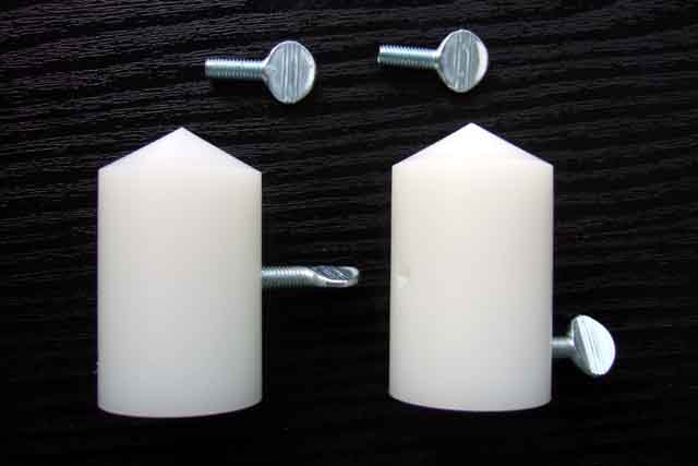 I get the Moss gauges with a replacement UJ and track-rod ends, so measure them myself, at 44.58 for the CB and 30mm for the RB and all V8s. The latter UJ is 31.5mm, and as that column has a fixed shaft this means that a small gap has to be left between the tips otherwise you cannot get both clamp bolts through the UJ. Doesn't matter for the earlier columns as the inner slides in and out to suit. As I've got to
change the steering column UJ, and the rack has to be pulled forward for that, it's a good opportunity to check the alignment at the same time (which is why I bought the gauges with the UJ ...).
I get the Moss gauges with a replacement UJ and track-rod ends, so measure them myself, at 44.58 for the CB and 30mm for the RB and all V8s. The latter UJ is 31.5mm, and as that column has a fixed shaft this means that a small gap has to be left between the tips otherwise you cannot get both clamp bolts through the UJ. Doesn't matter for the earlier columns as the inner slides in and out to suit. As I've got to
change the steering column UJ, and the rack has to be pulled forward for that, it's a good opportunity to check the alignment at the same time (which is why I bought the gauges with the UJ ...).
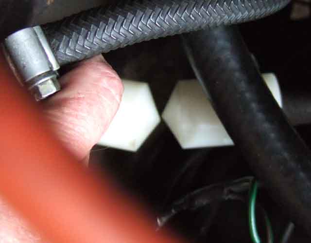 The gauges are a nice snug fit on the shafts which is good, and one thumbscrew in each gauge going into the shaft groove holds them firm. The tips are about 1/8" out, part horizontal and part vertical, which could have contributed to UJ wear, but there is some up and down and side to side play in each shaft so the end result would have been not much by way of sideways forces on the UJ. I'll need to adjust the sideways misalignment at the column mountings, so I opt for seeing if I can get the vertical alignment corrected there as well, rather than fiddling with shims at the rack. This style of collapsible (not the later full energy-absorbing) column used on UK 72 and 73 models is supported by two body brackets, one up by the dash and another one further down under the shelf.
 Both are slotted so each mounting can move up or down independently giving quite a large change in vertical position of the UJ end of the column shaft. I find the top can go up just a little bit and the bottom down, which puts the gauge pointers in perfect vertical alignment.
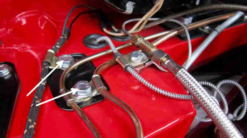 For horizontal alignment the lower bracket has two bolts up through the heater shelf (with support clips for brake and clutch pipes and harness) and with the nuts slackened the bracket and hence the UJ end of the column can be moved from side to side. With this column the inner can slide up and down freely so you need to pull the wheel up a bit while moving the column, as if the gauge points overlap they will jam and possibly get damaged. Then it's unbolt the rack again and pull it forwards as before to remove the gauges and fit the UJ, lining up the splines by eyeballing the front and rear tyres each side to get to get the steering straight, then fitting the UJ with the wheel in the straight-ahead position, and finally bolt the rack back down. The UJ only attaches to the column shaft in one position as the cut-out for the clamp bolt is cut straight across, but the rack shaft is cut all the way round (oddly the V8 only has notches in both shafts). Really I should have put a paint-mark on the rack-shaft in line with the slot in the clamp before removal, but as I've got to change the track-rod ends as well and then get the alignment checked, it'll come straight in the end.
April 2023:
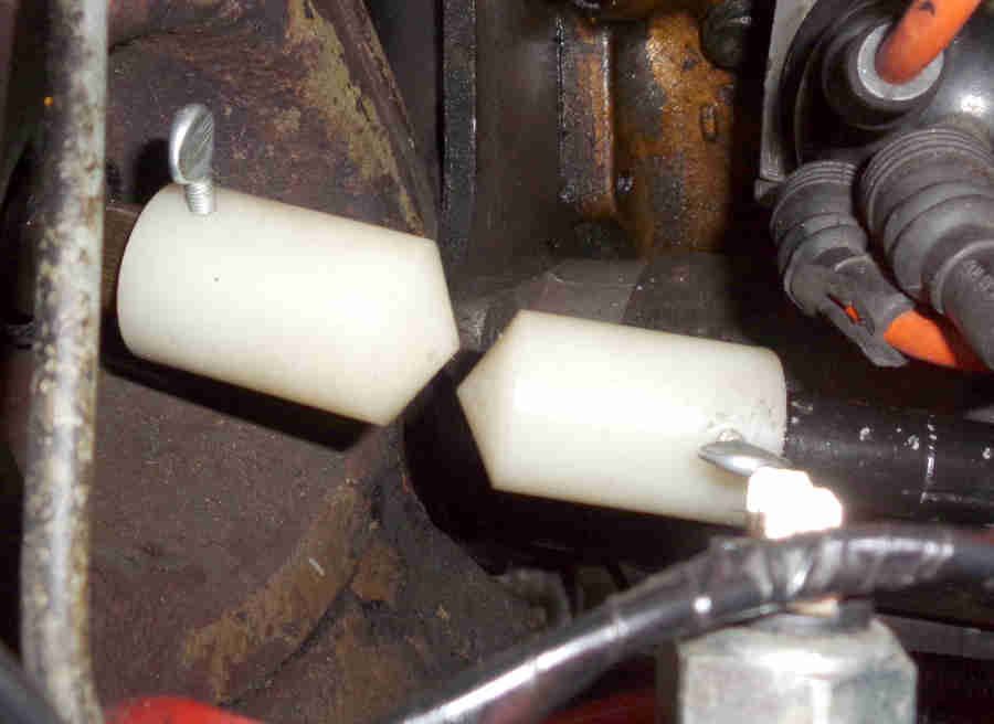 For Bee's new rack none of the column adjustments would get the tips in line - rack shaft too low - so the upper mountings to the cross-member had to be shimmed.
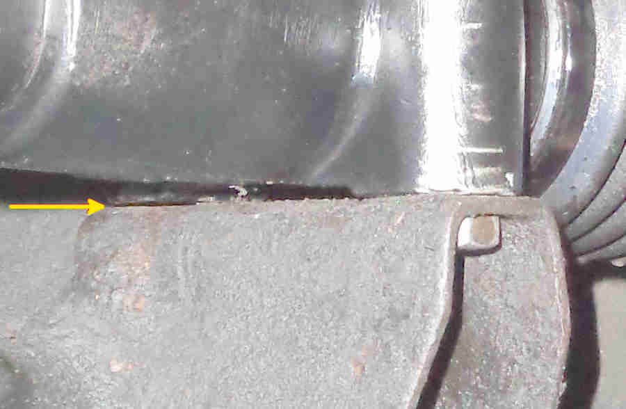 The other potential issue is that both mounting points on the rack may not sit square to the brackets on the cross-member, and that proved to be the case, the upper one on the near-side had a 12 thou gap when the other three bolts were nipped up, so that side is going to need a spacer 12 thou thicker than the upper off-side. In the end I put a 63 thou spacer on the off-side upper and an 85 thou on the upper near-side. Getting them in was a fiddle as neither of them can be fitted with fingers. In the end I did them by lifting the rack up with one hand while I slid them into position from underneath using an open-ended spanner to guide them. I had bolts in position and protruding from the mounting, pushed the spacer up to touch the threaded end of the bolt, then lifted the bolt and pulled the rack forwards a bit to put the bolt over the hole in the spacer (without knocking it out of position ...), lower the bolt into the spacer, then wiggled the rack, bolt and spacer about until the bolt was aligned with the threaded hole in the cross-member bracket. Bolts with a ground point would have been easier ... and had spacers been needed at the lower bolts then easier still!
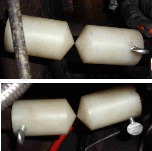 They raised the rack shaft pointer above the column pointer, but I had put that in its lowest position to try and meet the rack pointer before shimming, and it was a simple job to raise the column pointer using the two column brackets.