


portions by Michael Beswick
|
Part 2 - Electrical systems, typical faults, causes, symptoms, and diagnostic techniques
Click here for Part 1 - Terminology

|
Car batteries contain a large amount of energy and can discharge it very rapidly under the wrong conditions, generating large sparks, toxic fumes, and even exploding showering corrosive liquid around. Not all batteries have polarity markings, on classic cars battery cables are not usually colour-coded for polarity, and the battery terminals and connectors do not usually have insulating covers. Great care must be taken to ensure the 'live' or 12 volt terminal does not accidentally contact the car body or a large spark can be generated which can ignite battery gases, and tools or other metal parts can become welded and glow red-hot.
|
|
Many MGBs and other classics of the era have two 6 volt batteries instead of a single 12 volt battery, and the two 6 volt batteries are connected together with a link cable. Both ends of this link cable must be considered as being 'live', as well as the 12 volt terminal, and need the same care to prevent accidental contact with the car body.
|
|
When doing any work involving any battery terminal, always disconnect the earth cable - the one that goes to the car body - from its battery post first, and reconnect it last. This is irrespective of whether your car is positive earth or negative earth, twin 6 volt batteries or single 12 volt battery. Many sources of automotive information say to always remove the negative connection first before the positive, but they are only thinking of 'modern' cars, not classics. I repeat, always remove the earth connection first and replace it last, regardless of polarity, and that applies to all cars i.e. moderns as well as classics.
|
|
It is absolutely vital that batteries are securely clamped into their cradles. Unsecured batteries have started fires in accidents, including this horrific incident where the occupant was trapped and burnt alive.
| |
The MGB along with most classics has a 12 volt electrical system, and has either one or two batteries under the battery cover on the shelf behind the seats.
 Chrome bumper MGBs (and others of the era) originally had two 6 volt batteries connected in series with a link cable so as to deliver 12 volts.
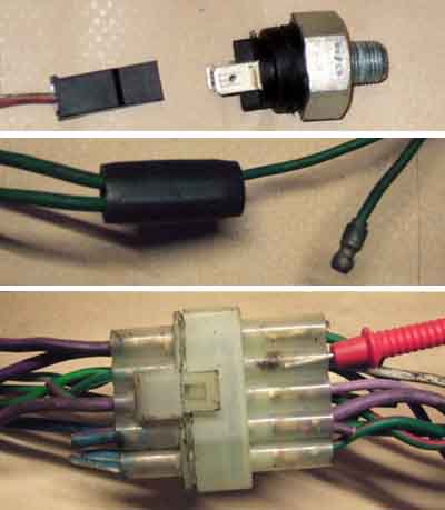
To indicate polarity to others I've wrapped a strip of red plastic insulation - a spiral cut off a red battery cable - around the main cable that feeds power to all the circuits on the car, as well as round the positive end of the link cable.
 Also shown is an armoured link cable available from various sources such as Motaclan/Leacy. This cable goes over the prop-shaft and it is essential that it is clipped to the back of the heel-board as high as possible. The armouring prevents the cable chafing in the clip, if this cable shorts out even though only one battery will be affected fire can still destroy the car.
 Rubber bumper cars have a single 12 volt battery as shown here. This battery has a red protective cover over the 12 volt i.e. positive terminal and connector of the battery.
Some owners have modified chrome bumper cars replacing the two 6 volt batteries with a single 12 volt battery, usually for reasons of cost. However the 6v apertures and cradles are smaller and you end up with a lower capacity battery.
Battery capacity is given in 'cranking amps' - CA or 'cold cranking amps' - CCA. As the ability of a battery to deliver the high current used for starting reduces as the temperature reduces, the CCA figure gives a better idea of what a battery can deliver in winter, which is when most battery failures occur. Some suppliers use 'starting power' which is perhaps easier to comprehend. Battery capacity may also be specified as so many Ampere Hours, which is a measure of how long a battery can deliver a lower current such as for parking lights. More information on these terms and how they apply to the MGB here.
Without going into the details of battery design and how they work, each battery consists of a number of 'cells' - three in each of the 6 volt batteries and six in the 12 volt battery. The only reason for mentioning this is that each cell contains a liquid consisting of acid and water, and the level of this in the cells must be right for the battery to work correctly. Again care needs to be taken as the acid can burn your eyes and skin and make holes in soft materials like seat covers and carpets, and can also can be explosive. However under normal circumstances the only attention they need is to periodically have distilled or de-ionised water added to the cells, which in itself is perfectly safe to handle. Having said that most 12 volt batteries these days are 'sealed', and don't even need that attention.
Batteries can gradually lose charge on cars not used for long periods, particularly where things like stereo systems and alarms have been installed. This can be a particular problem on modern cars, where even two to four weeks can be enough to discharge a battery so that it cannot start the car. Easy enough to jump-start the car from a jump pack or another car, but great care needs to be taken particularly when using jump leads between two cars. Information on safe use of jump leads can be found here.
To prevent this gradual discharge you can install a battery cut-off switch. These switches also act as an immobiliser, and can also prevent electrical faults causing damage while the vehicle is parked. I've witnessed a Transit van cranking itself across someone's front garden when a fault developed in the starter circuit. The switch - if accessible from the drivers seat - is also valuable as a safety device. There is much unfused wiring in classic cars, and in the event of a short-circuit on any of these wires much damage could ensue including total loss of the car to fire. Being able to stop the engine and switch off the power in seconds is far preferable to having to stop the car, get tools, access the battery, and disconnect the earth cable while wiring is burning. More information on cut-off switches here.
Although we talk about the MGB having a '12 volt' system a fully charged battery that isn't powering anything will actually measure close to 12.8v. If we now switch on some electrical circuits, its voltage will begin to drop, and a high power component such as the headlights will cause it to drop more and faster than, say, a low-power component like an interior light bulb. How much and how fast the voltage drops is also a factor of the power of a battery as well as how well charged it is - a weak or partially discharged battery, or a small capacity battery, will drop further and faster than a fully charged high-capacity battery.
In order to recharge a battery a voltage of greater than 12.8 volts is connected to its terminals, which is the purpose of the dynamo or alternator. This voltage has to be carefully controlled - too low a voltage won't recharge it properly and the battery will fail in a few months or weeks, and too high a voltage will damage the battery. The controller for a dynamo is called the 'control box', is mounted externally to the dynamo and typically recharges the battery with between 14 and 15.5 volts. This variation is due to the control box containing mechanical components which have adjustment tolerances as well as being sensitive to temperature. Alternators use an electronic voltage regulator which on all but the earliest versions is fitted inside the alternator body. It recharges with between 14.3 and 14.7 volts - not such a variation as the dynamo and its control box as there are no mechanical components to adjust and it varies less with changing temperature. These are the sort of voltages you should see on your electrical system, at various points, with the engine running at 2000 rpm or so, and it tells you your charging system is working correctly. Never run the engine without a battery being connected, high voltage pulses will be generated which can damage electronic systems and blow bulbs.
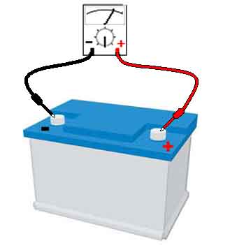
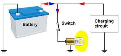 While the dynamo or alternator is outputting a voltage higher than the normal battery voltage it is charging the battery. Under these conditions when you turn on electrical circuits, it will be the dynamo or alternator that will be powering those circuits, as well as charging the battery (red arrows). So under normal circumstances, when you are driving the car it is the dynamo or alternator that is powering everything and not the battery.
However as with all things there are limits, and the limit here is how much current the dynamo or alternator is able to output. The dynamo used on the MGB can supply up to 22 amps, and the alternator can supply from 34 to 46 amps, depending on the year and model, later cars and the V8 having higher output alternators. Alternators on modern cars can supply up to a hundred amps or more as modern cars have so many more electrical circuits, some of them requiring a lot of power. The charging system doesn't suddenly 'switch off' if the current taken by your electrical circuits exceeds the maximum output available. What happens is that as the dynamo or alternator is asked to supply more and more current to electrical circuits, its output voltage and hence the voltage seen throughout the car will start to drop. As long as that voltage stays above 12.8 volts then it will still be powering everything as well as putting some charge back into the battery, albeit perhaps a very small amount. But if your electrical circuits start to take more than the charging system can provide, then the output voltage will fall below 12.8v, and at that point the battery starts to supply some of the current (blue arrows), and hence is discharging, despite the engine running. The more the current being taken by your circuits exceeds the output of your charging system, then the more the battery will be providing, and the further and faster it will be discharging. More information on testing your charging system output here.
The other thing to bear in mind is that the output from charging systems is not constant but varies with engine speed i.e. how fast the dynamo or alternator is spinning. It goes up as the engine speed increases, to the maximum output currents indicated above - from manufacturers documentation typically 3000 rpm in the case of the dynamo and 6000 rpm in the case of the alternator. Below those speeds the maximum current that the charging system can supply may be less than quoted, so at low engine speeds your battery will begin to start supplying some of the electrical circuits and hence start to discharge with fewer things turned on, compared to when you are using high engine speeds. The alternator is less affected by this because of internal and external differences which means it usually spins faster than the dynamo at a given engine speed, and hence gives more of its output at lower engine speeds as well as having a higher peak output. An alternator should be charging well at idle - albeit not at it's full output - even with several electrical circuits turned on, whereas a dynamo will only just be charging at idle and turning just one or two circuits on may be enough to start discharging it. This can be a problem for dynamo-equipped cars stuck in traffic on a winter's night with headlights, wipers, heater fan and perhaps brake lights on, but shouldn't be for alternator-equipped cars. Having said all that both systems should be charging satisfactorily under normal driving conditions i.e. 30mph upwards. There is more information on dynamos and alternators here.
Even with a sound charging system batteries have a finite life, and the continual discharge during cranking and recharging during running gradually reduces their effectiveness. This is not usually seen as a drop in voltage as the car is being used, more likely over a period of years it will crank slower each time you go to start the engine. And if for any reason the engine doesn't start quickly the battery will 'go flat' sooner, i.e. lose all its charge and no longer be able to turn over the engine, compared to when the battery was new. This is most noticeable in cold weather, when the oil is thick, the engine harder to turn, and the battery finds it harder to deliver high currents. It's why a battery is more likely to fail in winter, particularly when there is a 'cold snap' or sudden spell of cold weather, which is a feature of the UK climate.
If you have flattened your battery, you may think that once the engine has been started e.g. with a jump-start your battery will be recharged over a period of time by the dynamo or alternator. Yes it will, but a battery that has become so discharged it is unable to start the car will only ever regain half its capacity from the vehicle's own charging system. Even a battery that has only lost 30% of its capacity will not regain all of it. The battery will work for a while, but it will fail to start the car again, under less arduous conditions than before, and you will probably come to the conclusion that it needs replacing. A new battery will solve the problem, but there are ways of charging batteries from external sources that will restore near full capacity, such as with a 'boost' charger or a 'conditioning' charger. A 'trickle' charger will not recover capacity as they output less than a dynamo or alternator. More information on chargers and charging here.
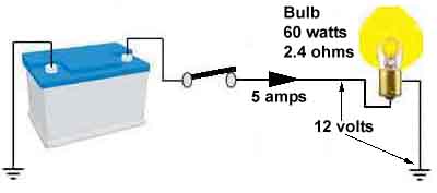 Bad connections add resistance to an electrical circuit, which reduces the current that can flow in a circuit, which reduces the voltage that reaches the component being powered. This results in dim bulbs, slow cranking, weak horns and so on. However there has to be some resistance in the circuit or an infinite current would flow, and you would need infinitely thick wiring to carry it. Taking the 12 volt, 60 watt headlamp bulb as an example and using the Ohm's Law wheel in Part 1 we can see that R = V * V / W or 12 * 12 / 60 which equals 2.4 ohms, that is 'good' resistance, and limits the current through that bulb to 5 amps.
 There is another source of resistance which comes from bad connections inside switches, where wires join components, or where wires join each other - this is bad resistance. Most circuits take a tortuous path to get a complete circuit from battery, through switch and component and back to the battery again, usually via many connection points. For example the indicator/turn circuit: Battery - battery cable - brown circuit - ignition switch - white circuit - No. 2 fuse - green circuit - hazard flasher switch - indicator flasher - indicator flasher switch - indicator lamp holder - indicator lamp - indicator lamp holder - earth - battery. And as well as all the item to item connections implied above there are also a number of in-line connectors in many of the interconnecting wires. In theory most components should receive the full 12v, but in practice every connector and length of wire imparts it own bit of resistance.
Straight out of the factory these additional resistances are minimal and for practical purposes can be ignored, but as our cars get older these additional resistances increase. As the resistances increase the current through the circuit reduces, and each of these additional resistances has part of the battery voltage 'lost' across it, which means that there is less voltage available for the end component. These bad connections build up over time from corrosion in connections caused by dampness and oxidisation, and inside switches from the tiny spark that can occur when the contacts open to disconnect a circuit.
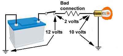
Take your stop lights which total 42 watts (two 21 watt bulbs in parallel) and draw about 3.5 amps from the 12 volt supply. Assume there is a bad connection between the voltage source and the component that happens to measure just 0.75 ohms. The lamps have a working resistance of about 3.4 ohms, and adding the bad connection becomes 4.1 ohms. The current is now 12 / 4.1 or 2.9 amps i.e. less than the original 3.5 amps. Why does this matter? Use Ohm's Law again but this time transpose it to calculate the voltage lost in the bad connection i.e. 2.9 amps times 0.75 ohms which equals 2.1 volts. The significance of that is that there is now 2.1 volts less reaching the stop lamps, i.e. slightly less than 10 volts, so they won't be as bright as they should be, which is the last thing you want from classic car lighting.
A reduction in brightness is bad enough, but the flasher units used in cars of this era are very sensitive to reduced current, causing a slower flashing rate or not flashing at all, and it can be a time-consuming process tracking down small amounts of unwanted resistance in the many connection points of this circuit. There is more information on diagnosing faults in the indicator/turn signal circuit here.
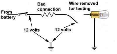
However this feature of electrical circuits with bad connections - different voltages at various points along a circuit - means that by measuring voltage in circuits that aren't working as they should, you will be able see if it is bad connections that are causing the problem. Even more importantly the 'lost' voltage can also be measured with your test meter, and this can be used to find exactly where the bad connections are. This is probably the single most important thing to understand when diagnosing faulty circuits.
But going back to 'good' resistance, whilst we can use the wattage of a bulb to calculate its resistance, it is important to realise that is the working resistance when the bulb is glowing at full brilliance i.e. white-hot. When the bulb is off and cold it exhibits a much lower resistance on a test meter - a 60 watt headlamp bulb for example measures only 0.1 ohms when cold. This effect - of resistance increasing with heat - is called the 'positive temperature coefficient' of a conductor, and means that when first switched on bulbs take a high current until the filament has heated up. This is a major cause of failure in replacement brake light switches. More information on brake lights and switches here.
Motors also take less current when running normally than the resistance shown by a test meter would indicate. In the case of the heater fan motor the measured current is about 4 amps, which implies a resistance of 3 ohms. But measuring the resistance with the motor stationary displays about 1.5 ohms, which would imply a current of about 8 amps. Again that is due to a physical characteristic of motors - in this case 'back-emf' which is where a spinning motor generates a voltage in opposition to the supply voltage, which reduces the current the motor takes. This also results in the initial switch-on current being significantly higher than the running current i.e. once the motor has got up to speed. But if the motor is seized or otherwise jammed the higher current will flow all the time, and the heat generated usually causes the motor to burn out, which can extend to catching fire and spreading to the rest of the car. Incidentally, this 'back-emf' is also generated when the motor is being spun by mechanical means, which is basically how a dynamo works.
Other than the specific issues with brake light switches and stalled motors I only mention these factors to show that taking resistance measurements on circuits when looking for faults can be misleading.
Bad connections have bad habits: When current flows through any resistance it generates heat, which is why light bulbs get hot when they are glowing, for example. The same happens where current is flowing through a bad connection, these can heat up as well, which is one reason why switches and connectors can melt even without a short-circuit fault. This leads to another very important thing to understand when diagnosing electrical faults. Bad connections are almost always variable in their nature, with variations in resistance and hence current and 'lost' voltage in them being caused by vibration and heat. There is inherently significant vibration in a car, and considerable temperature variation in the engine compartment between just started and fully up to temperature as well as anywhere on the car between seasons. So with bad connections generating heat, and heat and vibration causing bad connections to vary, fault symptoms become variable and the causes difficult to track down.
If you pull wiring around and waggle connections you can alter the resistance of the bad connection, which may cause the symptoms to get worse, or indeed the fault may go away - for a while. Sometimes this can help you find the location of a fault but it's not reliable, and can be confusing. Wiggling a bad connection may well make the fault go away, but unless you open up the connection and clean, tighten if loose, or replace the parts if heavily corroded it is bound to return. Components themselves can develop internal weak connections which vary when they get hot causing the component to fail, a known failure mode of some ignition coils for example. Ignition coils do heat up in use, that in itself doesn't necessarily indicate a fault, but there are limits. More information on hot coils here.
Similarly because heat can cause a bad connection to vary, measuring resistance to look for bad connections is unreliable. In almost every case the current in a circuit from a test meter measuring resistance will be microscopic compared to the current that would normally be flowing. Heat from normal current could well be causing the bad connection to change and hence a fault to become apparent, but when measuring resistance with a test meter there won't be any heat in the bad connection, so it is quite likely to react differently, and what your test meter will be telling you is not the same as what the circuit itself will be telling you when powered normally - more confusion.
But the opposite side of that particular coin concerns switches. These mostly have brass or silver contacts which can develop a thin film of oxide when not used for a while. Test these with an ohm meter and you may well see some resistance and think the switch is faulty. But that's because the tiny current from the meter cannot fully break down the oxide. Apply normal circuit conditions to the switch and measure the voltage between its closed contacts, and you will most likely see little or no voltage lost in the switch. This is because under normal working conditions the 12v system voltage will break down minor oxidisation, and allow a normal current to flow. An exception to this is the standard fuel pump, where the contact points have oxidised during storage or a long period of not being used. Only mechanical abrasion will clean off the oxidisation, and new pumps contain a slip of paper to this effect and ask you to clean the contacts before returning the pump as faulty. More information on diagnosing the fuel pump here.
For all these reasons the only reliable indication of bad connections, and where they are, is by measuring voltages when the circuit is connected and powered 'normally'.
The wiring in car systems is almost always copper as copper has a lower resistance to the passage of current than other metals such as steel (which would be cheaper) or aluminium (which would be lighter). But even copper wires have a certain amount of resistance, and so will heat up when a current is passed through them. When designing an electrical system the amount of current that the wire will be required to carry is taken into account when deciding how thick the wire needs to be - just like in house wiring cabling for power sockets is thicker than for lighting circuits. The result is that under normal circumstances you won't detect any rise in temperature in a wire. Where factory wiring does heat up and burns the insulation the reason will always be that there is a short-circuit fault somewhere causing a much higher current than anticipated to flow in the circuit. Note that this can also happen with owner modifications where wire of too small a gauge (thickness) has been used to connect a high power component like a powerful lighting or audio system, or the wiring has been done incorrectly and caused a short-circuit. Most circuits in an MGB don't take more than about 5 amps. A pair of headlights takes about 10 amps, but this can double to 20 amps if you should happen to operate your headlamp flasher while your dipped beams are on, and is why headlamp wiring is normally thicker than most other wiring. However the starter takes about 200 amps as a lot of energy is require to spin the engine, which is why the cables to the battery terminals, the starter solenoid and the starter, and the engine or gearbox earth strap, are as thick as they are.
There is also the complication that not every component has its own earth connection to the body, in most cases several are joined together in wiring first, then one or several wires will be connected to the body at one of the earthing points. If one of these earthing points develops a bad connection then the circuits connected to it can interact in apparently weird and confusing ways.
There are typically only three wired earthing points to the body in an MGB - in the engine compartment, behind the dash and in the boot, plus the two most important - at the battery without which nothing will work, and at the engine or gearbox. This latter is a wide braided strap for flexibility as the engine moves on its rubber mounting points during use. If this strap fails the engine will either crank slowly or not at all as it is the return path for the 200 amp cranking current. However the starter circuit is like any other circuit in that its current will try to get back to the battery any way it can. There are several other metallic connections between engine and body such as the heater, choke and accelerator cables and the temperature gauge capillary tube and speedo cable. With a bad engine or gearbox earthing strap these can all get very hot during cranking and indeed suffer damage.
A few components are bolted directly to the body and make their earth return connections that way.
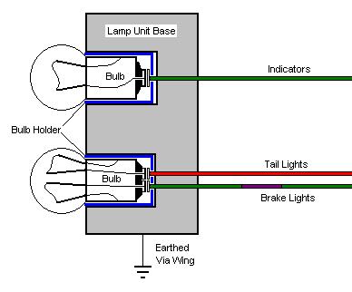 Tail light assemblies with three circuits sharing a common earth can be particularly difficult as one bulb circuit will try to earth through another circuit if a shared earth is poor. Various lights will flash on and off or go dim and bright when they shouldn't when two or more circuits are powered at the same time - known as "disco-ing" in MOT circles. Each bulb earths to its bulb holder, the bulb holder to the light unit base, and the light unit base to the car body. If the bad connection is between the bulb and its holder, then in the case of the stop/tail bulbs the stop and the tail lights will interact, but the indicator bulb will work correctly. But if the bad connection is between the light unit base and the car body, then all three lights will interact. This discoing can extend to the other corners of the car from the faulty corner, even though the circuits are, on the face of it, separate, and there is nothing wrong with the connections at the other corners. Current in any circuit with a bad shared earth will try to get back to the battery any way it can, including back up the wires and through components of the other circuits affected by the same earthing fault.
A quick simple test is to add a temporary earth; If adding an earth between the tail light assembly and a good earthing point solves the problem, then the fault is the connection between the light unit and the body. If it does nothing, then the fault is either with the bulb or bulb holder, and there have been instances where the bulb holder is making a poor connection to the light unit base.
Chrome-bumper front parking/indicator assemblies i.e. two circuits are the same in that they earth through their physical fixings to the wings. Rubber-bumper front indicator units have an earth wire going to the cluster in the air intake by each headlight, but in any case only have one circuit. Another problem area is the earthing of the bumper-mounted number-plate lights, which is also through their physical mountings.
See also these thoughts from Felix Weschitz on getting good earth connections. Additionally I always daub Waxoyl on all nuts and bolts, whether on the body or not, electrical connections or not, to delay the onset of the dreaded corrosion particularly where things are bolted to the body and where the paint is inevitably damaged.
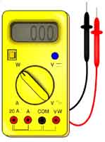
| In order to measure voltage, current and resistance you need a multimeter. Cheap home-use meters will be able to measure all three, more sophisticated and expensive versions will measure other automotive parameters such as engine revolutions per minute (rpm) and ignition characteristics. Most these days will have digital displays, older instruments will be analogue i.e. with a pointer physically moving across a printed scale. After you purchase one, read the instructions and practice measuring voltages and resistances with it, and there are strict Do's and Don'ts to be observed when using one. |
Okay, you've been wandering around Halfords and whilst picking up other things bought yourself a shiny little electrical test meter. You fitted the battery maybe even read the instructions and it's now sitting in the garage until you need it.
Before you actually start to use it, it's worth examining it quite closely. Firstly the leads are too short, they are covered in plastic, and as you always do this the middle of winter, the lead are stiff when cold and pulling on them always causes the meter to fall off whatever you put it on. The second problem is that in almost every case you will need to have one of the meter leads attached to a Good Earth. How do you find one of those? By connecting the meter between one point that should have 12v, like the brown at the fusebox, and the earth you are proposing to use for your tests. If the meter shows 12v then you can proceed. If it doesn't, then either your earth is no good, or your 12v point is no good, or maybe both are no good (or maybe your meter is no good...). So try other points until the meter shows 12v. At this point you wish you had bought a package of ancillary leads that included crocodile clips (which cost as much as the meter..)
 As in the image above meters usually have at least one red socket for the positive probe, and at least one black socket for the negative probe, and there may be others, for various test functions. Usually either lead will physically fit either socket, but of course the convention is to plug each lead into the same colour socket.
When measuring voltage and current with an analogue meter the probes need to be connected to the circuit 'the right way round', that is with the red or positive probe connected to the point in the circuit that is positive with respect to where you will position the black or negative probe. In general what this means is that if your car has the batteries connected for positive earth, then usually the black probe of the meter needs to be connected to the terminal or wire being tested, and the red probe to a convenient earth. If your car has the batteries connected for negative earth then the red probe will go to the wire or terminal being tested and the black to a convenient earth. If you get the probes the wrong way round the needle will try to move backwards, although this is very unlikely to damage the meter. Most if not all digital instruments will display the voltage or current no matter which way round the probes are connected, although if you have the probes the wrong way round they will usually display a minus sign '-' in front of the numbers.
For most of us we will only ever use the 12 V DC range. About the only time you would use an ohmmeter is when you are testing a component for continuity such as a fuse, a bulb, a relay or solenoid winding. But even those, and particularly a fuse, can show continuity with an ohmmeter, but go open-circuit when a larger current is drawn. So for problems on circuits where the fuse shows continuity, you will have to go back to using the voltmeter or test-lamp both sides of the fuse and fusebox while the circuit is being powered and drawing (or trying to draw) current. More information on fuses and fuseboxes here.
It is sometimes necessary to check a wire itself. The meter probes usually have sharp points to push through the insulation and make contact with the wire. They also have a habit of making contact with your fingers. To avoid this, find a small block of wood or plywood; file a 2-3mm groove along its length. Drill a 2-3mm hole mid way along the groove. Now by placing the wire in the groove you can pierce the wire and not your fingers. Sometimes it may be necessary to make a semi permanent connection. A domestic pin or similar can be forced through the insulation and wire exiting through the hole. Then a croc clip can be attached to the pin. Remember that, depending on the use of the wire the pin may become "live". Much wiring is unfused, but pretty-well all wiring will carry 12v at some point in time. Be careful that your test clips etc., do not bridge wires or connections to other metal parts, which might be at earth potential, which can damage the wiring.
 One of the first difficulties is that different faults require different types of measuring kit. Sometimes there is an overlap and in most cases a test-light will work as well as a meter. This is a small 12 volt bulb or LED, inside a probe similar to a screwdriver, with a point at one end and a wire with a crocodile clip at the other. Or it could simply be a spare bulb with two bits of wire soldered to it. The crocodile clip is put on a convenient earth point, and the probe placed on another connection or terminal point. If there is 12 volts present at the connection or terminal the bulb or LED will glow, if not it won't. It can also be used to check for an earth, by putting the crocodile clip on a convenient 12 volt source such as at the fuse box. Always check the test-light first by putting the probe on a known source of whatever it is you are looking for, much time has been wasted looking for a broken connection when it has been the crocodile clip on a poor earth or the test light that is broken. For example, when looking for 12 volts, the crocodile clip will be on a convenient earth point, so touch the probe to, for example, the brown wire terminals of the fusebox, as these should have 12 volts all the time. When looking for an earth and the crocodile clip is connected to a 12 volt source, touch the probe on a convenient earth point such as somewhere on the engine.
In other cases such as an indicator/turn-signal fault where they light but don't flash, test-lights are not sufficiently accurate (how can you tell how bright or dim the bulb is...), which is when you need a meter as voltage drops small enough to affect the circuit may not be seen on the test-light. There is more information about diagnosing slow or non-flashing indicators here.
Horns are another circuit where a small drop in voltage to the horns causes a significant reduction in sound output and where a voltmeter is preferable for diagnosis. More information of diagnosing poor horn output here.
There is only one type of diagnosis where a particular type of 'test-lamp' is preferable to a meter, and that is if you have a continually blowing fuse. You use a high-wattage bulb in place of the fuse - purely during diagnosis - and when the short is present it glows at full brilliance and when the short isn't present it glows dimly or not at all. More information on diagnosing blowing fuses here.
 The most important thing to remember when making tests with either device, is that the circuit must be fully connected and powered 'normally' in order to give useful results, and this all goes back to resistance - the natural working resistances of components on the car, and the inherent resistances of the test meter and test-lamp.
Remember our volt-meter has an inherent resistance of hundreds of thousands of ohms, however probably every component in the car will have a resistance of less than 10 ohms. If a component isn't working so you remove a wire from it and test the wire for 12 volts, you may well see 12 volts displayed. But when you connect 12 volts from another source via a temporary wire to the same component, the component works! How can this be? It's all to do with relative resistances in a series circuit. If the normal circuit for the component has a bad connection measuring, say, 1 ohm between the 12 volt source and where you test with your meter, then your meter will display 12 volts. This is because the resistance of the meter is so high, which means the current drawn by it is so low (in the order of millionths of an amp) that there is only a microscopic voltage 'lost' in the bad connection, so effectively all the 12v volts is still available for the meter to display. But when the wire is connected to the component a much higher current will flow, and much more voltage will be 'lost' in the bad connection, so the component cannot work correctly.
For that reason the wire being tested must by connected to its component, and the circuit powered as it normally would be, and the fault must be present when you take your voltage measurement, in order for the meter to show 'lost' voltage. Fortunately most connectors and component terminals on the MGB are 'open' and can be tested with a probe while assembled. Modern wiring has sealed connectors and terminals, which keeps out the damp and corrosion that plagues classics, but also prevents access for testing.
In our example with a bad connection between switch and component, if you connect your test meter between the output from the switch and earth, you will probably see 12 volts. But if you now test the other end of that wire when it is on the component you will see less than 12 volts. The difference between what you see here and 12 volts is what is being 'lost' in the bad connection. There is another way of testing for lost voltage and that is to connect one side of your meter to the output terminal of the switch, and the other side of your meter to the input terminal on the component. If there is a bad connection between the two then you will read the lost voltage directly. But the component must be connected and powered for these tests to be useful.
A meter will give you the exact voltages in a circuit, but a test lamp can be used to give an indication. However it does depend on the voltage differences being large enough to cause the test lamp to give different indications, usually as a change in brightness, and that is very dependant on the type of test lamp being used. LED test lamps in particular may need quite a large voltage difference before they give a detectable difference in brightness. Test lamps are most useful when a component isn't working at all i.e. there is an open-circuit or the bad connection is so bad that little if any voltage is reaching a component. A meter will show you tenths or even hundredths of a volt difference between two points, but by the same token don't make the mistake of trying to track down and eliminate every last tenth of a volt.
 As stated above small bad connections have a disproportionately large effect on the starter circuit because of the very large currents flowing. For example, using Ohm's Law, a 0.05 ohm i.e. five hundredths of an ohm bad connection in the headlight circuit will reduce the voltage at the headlights from 12 volts to 11.6 volts - not that much. But in the starter circuit that same resistance will reduce the voltage at the starter to 6.5 volts i.e. almost half! In fact it will be lower than that, as even the best car battery can't maintain 12 volts while cranking an engine. In practice the voltage at the terminal posts of a sound battery will drop to about 10 volts while cranking, and this is the voltage you should be using as the comparison when making voltage measurements elsewhere in the cranking circuit.
I have seen 3 volts 'lost' in battery cable and starter connections but the engine still cranked - albeit slowly - and started. Anything more than 1 volt is worth investigating, and you should be able to get it below 0.5 volts in total i.e. what is lost in the 12v cable and connections and the earth return connections. An important thing to note about bad connections in the cranking circuit is that in most cases these will result in reduced voltage to the ignition system as well, making starting even harder. There is more information on starter problems here.
There is one circumstance where you use a voltmeter, but connected like an ammeter i.e. in series with a circuit, and that is when you are investigating why the battery seems to be going flat while the car is parked, i.e. while everything is supposed to be switched off, aka 'battery drain'. More information on diagnosing battery drain here.
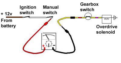 Very occasionally it may be necessary to measure currents such as when diagnosing the overdrive circuit. If the overdrive isn't operating, then the problem could be electrical, mechanical, or hydraulic. The first thing to do is to see if it is an electrical problem, as they are almost certainly going to be easier to resolve than hydraulic or mechanical problems.
You could use a voltmeter or a test-lamp, testing at various points along the circuit, but neither are going to indicate a problem if the fault is a broken OD solenoid winding or if there is a bad earth at the solenoid, meaning no current is flowing. Also to get at some of the connections for voltage measurements you will have to grovel under the car.
You could use an ohmmeter and measure the resistance of the solenoid winding to earth from a convenient point at the manual switch or gearbox harness bullet connector, but as already stated bad connections by their very nature can give variable resistance readings. An ohmmeter may show a good circuit, but a bad connection may be breaking down when the full current tries to flow.
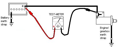
The only way to get a reliable indication that the OD solenoid circuit is working as it should - electrically speaking, is to use an ammeter, with the ignition on, manual switch operated, and the gearbox in an overdrive gear. That way, the circuit is being operated in its normal way, and any problem causing insufficient current to flow (or too much from a partially short-circuit winding or wiring) will immediately be shown on the ammeter. It also means only one test is needed to prove the problem is or isn't electrical, which can be done from a convenient point at a manual switch or connector.
Remember that an ammeter will only show whether the current in a circuit is correct or not, it won't help you determine where any faults are, no matter where you connect it. Also remember that analogue meters must be connected the right way round to correctly display current, the same as for voltage. The above example shows how to connect the meter for a negative earth system, i.e. where the 12v supply is positive with respect to earth. If no or insufficient current is flowing, then you will need to test the voltage at each of the points in the circuit to try and find out where the break or bad connection is. If you see 12 volts all the way to the connector on the wire that comes out of the solenoid, then the problem must be with the solenoid or its earthing. However there are only a couple of circuits where current is a useful diagnostic measure, click the links for more information on diagnosing overdrive electrical problems and ignition coil problems.
 When checking voltages at components check the component terminal i.e. its spade as well as the terminal on the end of the wire that slides onto the spade as corrosion can develop between the two. Factory wires are usually spot-welded to the spade connectors so pretty robust and the least likely to fail.
Test the voltage on each side of bullet connectors as either bullet could be making a poor connection with the connector sleeve. Bullets are crimped onto the wires in factory harnesses, usually OK, but at the front of the car you can get corrosion running under the insulation for several inches. In one case I've had the conductor strands corrode right through where the insulation was damaged on an unsheathed headlight wire under the wing.
Translucent multi-plugs such as these can have probes pushed in from the rear, however black and grey multiplugs are usually moulded onto the wires and pins and cannot be tested in this way.
Aftermarket modifications and repairs using crimp terminals often cause problems.
In all cases the connections must be together, not parted, or you will get incorrect results. More information on Connectors and Terminals here.
As an alternative you can use either the individual circuit elements as here ![]() , or these Advance Autowire diagrams which although showing all the circuits for a particular model in one diagram, has the components grouped together by function which results in much less wiring.
, or these Advance Autowire diagrams which although showing all the circuits for a particular model in one diagram, has the components grouped together by function which results in much less wiring.
However one major benefit of the original Leyland diagrams is that they show all the junction points for wiring and common earthing points, which are essential where the problem is one of strange interactions, rather than simply a circuit not working. Even in the latter case knowing how the 12 volt supply splits or branches off to components, and which are working and which are not, is very helpful in determining the likely location of a break in a circuit before you start, which can greatly reduce the number of points you have to test, as in the following example.
In this example the non-working component is a tail light bulb, so we need the correct wire, fuse and switch terminals for the sidelight circuit - in this case a 1970 and later model i.e. negative earth so a positive 12 volt supply - where ABCD are bullet or other type connectors.
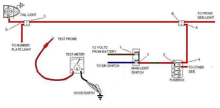
With meter on the 12v range, the negative black lead attached to a known good earth (for a negative earth car, reverse for a positive earth), you will touch the other (+'ve) probe to any connectors to the switch, then each of the Light Switch terminals, to each end of the fuse, then ABCD in turn. The circuit must be "on" to try this, even if the component - the bulb - is not working as it should.
- Put the probe on the inward terminal of the switch wire probably brown. If not good or a large drop, there is a fault in the wiring from the solenoid to the switch. This is a key circuit: the terminal on the solenoid is directly connected to the battery. If the fault is between the solenoid and the battery (unlikely) there are other major faults. The brown wire from the solenoid feeds several things within the harness - one of which is the head and sidelight switch.
- If there is no reading on the correct (sidelight) outwards terminal of the switch, then the switch is faulty. But this only is true if test 1 has been completed to eliminate the faults described.
- Test the input side of the fuse box
- Test on the outward side of the fuse box
- Test each connector A B C in turn. All OK?
- Test at D - if there is a zero reading this indicates the fault lies between C and D. If the reading is lower than that obtained at C there is still a fault between C and D but it is not a simple break - more likely a corroded terminal.
- So you've guessed it - you have to check both "ends" of bullet connectors (even then the contact between a bullet and its sleeve can be bad) and between any spade connectors (female) and the lugs (male).
- There may be a steady small reduction in the readings as you approach the component. In most cases this is OK, if it is bad enough then the component will not perform as it should. (A case in point is indicator circuits. There are 23 different connectors between the fuse box and the bulb all of which can drop a little voltage. In each case a little resistance is added to the circuit. This added resistance reduces the ability for current to flow. Where the current is insufficient it will not operate the "flasher unit" but will still light the bulbs to what seems to be full brightness).
- Remember that the component itself (in the case of a bulb,) can have poor connections. Usually caused by years of moisture corroding the contacts.
- So now you have tested right up to the lead that connects to the component itself: still you have 12v. But still the component does not work!
- If the component has a lead from it running to earth (usually black) test at this point. If there is still about 12v the component is OK. Your problem is a poor/bad earth.
- Many components earth through their fitting to the body. This can be poor but can be resolved by cleaning or fitting an "extra" lead to a separate earth.
And perhaps the most important thing to bear in mind is that just because you have found one fault, don't assume that is the only fault. In other words if you have one corroded connector causing a high-resistance joint, you could well have several, particularly at the front of the car behind the grille where they are exposed to the worst of the weather.