


|
Electrics probably causes the most problems for classic car owners, perhaps because usually you don't see, hear, feel or smell it until something starts going wrong! But electricity - unlike mechanical systems - operates to strict laws, so understanding the basics of electrical circuits should help you to work out what is going wrong when something doesn't work as it should. These words are written by someone with primarily MGB knowledge, but hopefully will be of use to owners of earlier MGs and other classics.
Part 1 - Terminology
Click here for Part 2 - Electrical systems, typical faults, causes, symptoms, and diagnostic techniques
Battery: The initial power source for the electrical systems in a car. Without a working battery you cannot start the engine by normal means, and if one is not even installed and connected you should not attempt to do so by other means as that can cause damage.

| The battery normally contains a large amount of energy and as such extreme care needs to be taken to avoid metal objects coming into contact with the terminal posts and connectors. Batteries must be securely clamped down to prevent them bouncing around and the terminals coming into contact with metal parts, of particular risk in cars like the MGB with a metal cover just above the battery. Anything that bridges the battery terminals together will generate a large spark which can ignite battery gases, get literally red hot and weld things together. These safety aspects are covered in the detailed technical section on batteries. |
Car batteries are capable of delivering a very high amount of energy for a short period of time as when starting the engine, as well as a much smaller amount of energy for a long period of time e.g. parked with the lights on. One terminal of the battery is known as the 'positive' or +ve terminal, the other is the 'negative' or -ve terminal.
Some sources purporting to give basic automotive electrical information also go into how a battery works i.e. the chemical reactions involved, current flow and electron flow, and which flows from positive to negative and which from negative to positive. But that's all irrelevant for fault diagnosis purposes and may just confuse, Google it if you are interested.
Voltage: This is the force of electricity coming from the source expressed as a number of Volts and given the symbol 'V'. It is often likened to the pressure of water forcing water out of a hosepipe, which at the very simplest level is not unreasonable. But further comparisons which some explanations of electrical circuits are fond of introducing such as reducing the size of the nozzle making the jet of water squirt further, are irrelevant as there is no functional equivalent in electricity. Voltage measurements are the single most useful thing in diagnosing electrical problems.
Current: This is the volume of energy passing through wiring and circuits, expressed as a number of Amps and given the symbol 'I'. The greater the rate of movement through the wire, the greater the number of amps. Another loose comparison with water can be made - it is like the speed of water coming out of the garden hose. And just as in a water system you need a large pipe in order to deliver a large volume of water, in electrical circuits you need a large i.e. thick cable to deliver a high current. Electrical systems in the vehicles considered here are 'direct current' or DC, unlike most house systems which use 'alternating current' or AC. There are good reasons for the difference, and why cars typically use 12 volt systems and houses typically use 240 volt or 120 volt systems, but there is no need to go into that here, Google it if you are interested. With a couple of exceptions the need for current measurements is rare in diagnosing electrical problems, and it can be hazardous.
Circuit:
 Electrical systems can only work when there is continuous path or 'circuit' for current to flow from a power source, to a component, with a return path back to the power source. Circuits typically consist of a power source such as a battery, a component that is going to be powered such as a light bulb, wiring to connect the source to the component, and a switch so that the component can be turned on and off. The same current flows through all the components in a series circuit.
Resistance:
 Resistance, as its name implies, 'resists' or restricts the amount of current that can flow in a circuit, expressed as a number of Ohms and given the symbol 'R'. And - in the last comparison with water and hoses - it could be thought of as a kink in that garden hose reducing the volume of water that can flow. The higher the resistance is, the lower current that can flow in the circuit. As the current reduces then so the voltage that reaches the bulb (for example) also reduces, and the bulb will not glow as brightly. Unwanted resistance from bad connections is probably the biggest cause of problems in classic electrics.
 So to put voltage, current and resistance into context, the voltage is trying to push a current through a circuit, but the resistance is trying to restrict how much current can flow in a circuit.
Ohm's Law:
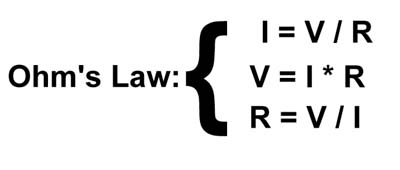 Voltage, current and resistance have a very close relationship and the interaction between them is governed by a strict law - Ohm's Law. This states that the current in a circuit is governed by the voltage applied to a circuit, divided by the resistance of the circuit, or I = V / R. But the same formula can be transposed so that where any two factors are known, the third can be calculated. However it would be unusual to use Ohm's Law when diagnosing faults in automotive systems, I only mention it to show that voltage measurements can be used to 'see' the effects of unwanted resistance in faulty circuits and help to locate faults. Probably all wiring in a car will be copper which has a lower inherent resistance than most other metals. Steel or aluminium would be cheaper or lighter but have a higher inherent resistance, so would need to be thicker, taking up more space to compensate. Again, with only a couple of exceptions, the need for resistance measurements is rare in diagnosing electrical problems.
Watts or Power:
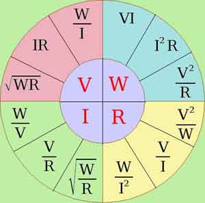 The Watt is the unit of power in electricity and is the product of Amps x Volts. About the only time you will see this used is in lighting and audio, and is an indication of how much energy a bulb - for example - consumes and how bright it is. For example if a headlight bulb is rated at 60 watts, on a 12 volt system, you can calculate the current that will flow by transposing the wattage formula i.e. Amps equals Watts divided by Volts, i.e. 60 / 12, or 5 Amps. When putting additional or more powerful lighting, audio or other systems on your car, this is the formula you should use to decide how thick the wiring needs to be. Other internet sources will give you guidance on what 'gauge' or thickness of wiring is needed for high power components.
Furthermore you can substitute the Ohm's Law formulae for voltage resistance and current into the wattage formula so that with any two values you can calculate the other two. For example to calculate the working resistance of a 60 watt bulb at 12 volts, use the lower right-hand quadrant of the calculation wheel, and the upper sector. Multiply the voltage by itself and divide by the wattage i.e. 12 * 12 / 60 equals 2.4 ohms.
Earth or Ground:
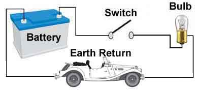 In practice and in all but very early vehicles 12 volts is supplied from the power source to one terminal of a component such as a light bulb, and another terminal of the component is connected to the car body. The other terminal of the battery is also connected to the car body, so it is the car body that completes the circuit to allow current to return to the battery. This return path is known as the 'earth' or 'ground' return even though it has no electrical connection with the earth or ground the car is standing on (the terminology is historical). The car body is used as the return path as it is much cheaper and simpler than doubling up on much of the wiring in order to connect everything back to the battery. The car body itself offers a very low resistance return path, even though it is steel and not copper. Imagine the body was squashed as far as it could be both top to bottom and side to side, and rolled into a cylinder, but keeping the same length as the original car. How thick do think the resulting column of steel would be? I've no idea, but it's going to be several inches, thicker than the thickest cable on the car, which makes for a very easy path for the current to flow back to the source.
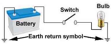 An earth return in circuit diagrams is usually depicted by the symbol shown here. All points in a circuit diagram with that symbol are effectively connected together, as if by wiring.
Live/12 volt and earth/ground terminals:
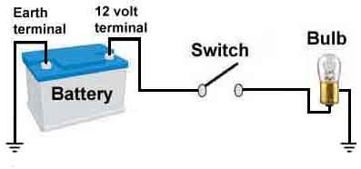 The live or 12v terminal feeds power to all the electrical circuits in the car, and it and its wiring must never be allowed to come into contact with the car body or severe damage can result (see 'Short-circuit' below).
The other terminal of the battery is connected to the car body and is the earth or ground terminal as described above.
In the vast majority of classic automotive circuits power comes from the 'live' or 12v terminal of the power source, via wiring and switches to components, and from components it returns directly via the car body to the battery to complete the circuit. In a few cases power is fed direct to a component, and the switch is in the earth return path.
Polarity:
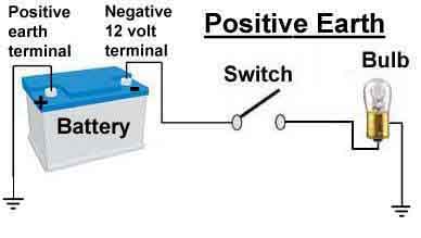
One of the more confusing aspects with classic cars, especially to people who only have experience of 'modern' cars, and one of the most dangerous to get wrong. 'Polarity' refers to which terminal of the battery, positive or negative, is connected to the car body, and hence is the earth or ground return terminal.
 Originally cars were wired for negative earth, then it changed to positive earth, then back to negative earth at various times. The reasoning behind these changes can be found here.
You have to be particularly careful with the MGB and maybe others of the same era as from inception to some point in 1967 the battery was wired for positive earth, but after that the negative terminal was connected to the body - negative earth or ground, which is probably how all modern cars are connected. However since leaving the factory some owners will have changed early cars from positive earth to negative earth for various reasons such as conversion from dynamo to alternator and for modern electronic accessories which can only be used with negative earth.
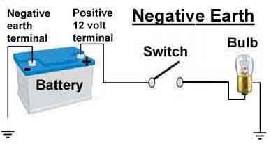 So if you are new to a particular car the first thing to establish is just what polarity it is, and that any labelling on the car and cable colouring at the battery reflects that. Note that the convention is that red cables or terminal covers indicate positive and black indicates negative. But usually on the MGB black are used for both and there are no terminal covers, which is why you need to be careful.
Note also that, regardless of polarity, power always comes from the live or 12 volt terminal of the battery, through wiring to components, and from components via the earth return back to the battery. In most cases the switch will be in the live wire between battery and component, but in a few cases it can be between the component and the earth return (e.g. early MGB wipers and most MGB horns).
Even more important is that if any stranger is to work on your car, and particularly if they are to use jump cables or a jump pack on your car, not only do they need to know the polarity of your car, but you also need to watch them like a hawk to ensure they connect them correctly. Incorrect connection can cause serious damage to wiring and components.
Also it is very important when you are going to work on battery connections, to always disconnect the earth terminal first, and reconnect it last. This is regardless of whether the battery is connected positive earth or negative earth. Ignore any instruction to remove the negative terminal first, only ever the earth terminal, and that is regardless of polarity. The reasoning behind this is explained in the detailed technical section on batteries.
Open-circuit:
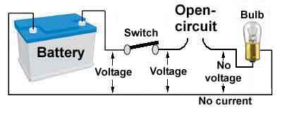 An open-circuit is where a fault has developed in a connection, component or wire that has either broken the circuit completely, or got to such a high resistance that there is effectively a complete break in the circuit as if a switch had been inserted, or a wire pulled off or cut. This is in addition to wires actually having fallen off components, or pulled out of connectors.
Short-circuit:
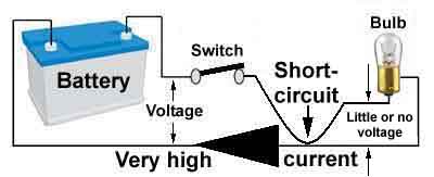 A short-circuit is the opposite of an open-circuit and is where a component has failed, or wiring has becomes damaged or has been connected incorrectly, such that much higher currents than normal can flow, and occurs when the current can find an 'easier' path back to the source than going through the component. It is called a short-circuit because the current is able to take a short-cut back to the source, and the very high currents that can flow can burn wiring and in extreme cases can destroy the car. Bear in mind that these very high currents flow in the whole of the circuit from the source, through the short-circuit and back to the source via any other components e.g. switches and connectors along the way, damaging those as well as wiring.
Fuse:
 Fuses contain a short length of thin copper wire which 'blows' or melts to disconnect the power if the current through them exceeds a certain level. As mentioned above if a short-circuit fault develops very high currents can flow, and serious wiring damage can result.
But if there is a fuse between the power source and the fault then the fuse will blow to protect the wiring. Modern cars are almost completely protected against this type of fault with dozens of fuses, but the MGB and other cars of its era can have as little as two, which leaves a lot of wiring unprotected. Note that in classic cars, unlike most electronic equipment, fuses are there to protect wiring, not components.
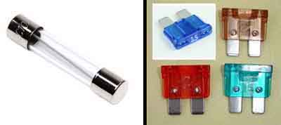
The picture shows a typical original glass cylinder classic car fuse on the left, and modern 'blade' fuses on the right. The fuse 'rating' - the maximum continuous current it is designed to carry under normal conditions - is stamped into one of the end caps, or on slip of paper inside, or screen-printed on the glass of the classic fuse. Modern blade fuses by the colour off and legend on the top part. The 'fusing' current - the current at which the fuse 'blows' - is typically double the 'continuous' current in automotive fuses.
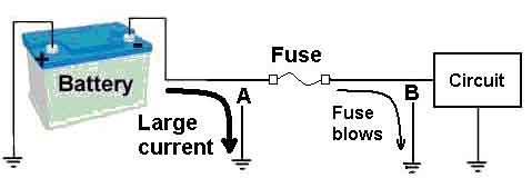
If you add fuses to circuits they need to be as near to the source of power as possible, not close to the component, in order to protect the greatest length of wiring. Consider a short-circuit to earth at 'A' above, and one at 'B'. At 'A' current will flow from the battery to earth - a short-circuit - before it reaches the fuse, so the fuse is bypassed and it will not blow. In this case a very high current will flow and the wiring will burn. But with a short-circuit at 'B' current is flowing though the fuse and that will blow breaking the circuit and protecting the wiring.
You could have just one fuse in such a position that it protected all the wiring, but if that blew you would lose all the circuits on the car and have no idea where the fault has occurred. In practice where multiple fuses are fitted it is where wiring splits off to individual circuits, so only that circuit fails if the fuse blows, and the fuse that has blown indicates which circuit is at fault.
Series circuits:
 In the basic circuit above we have a simple series circuit of battery, switch and bulb, and this is the case for a number of circuits on a car such as where there is a single interior or luggage space light, and for the starter motor, the wiper motor, an electric fuel pump, where there is a single horn, and others.
But some circuits have two or more components in series, as well as a switch and the power source. An example of this is the fuel gauge, where the power source feeds 12 volts through the ignition switch to the gauge, but instead of the other terminal on the gauge being connected to the earth return, it is connected to a variable resistance - the tank sender - inside the fuel tank, and the other side of the tank sender is connected to the earth return. As the fuel level in the tank goes down, for example, the resistance of the tank sender increases, which reduces the current flowing in the series circuit as we saw in the 'resistance' section above. This includes the fuel gauge, which is designed to move the pointer as the current changes, and so as the fuel level goes up and down the indication on the fuel gauge goes up and down.
Parallel circuits:
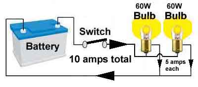 However many other circuits - mainly lighting circuits, have multiple bulbs like two headlights, four or more parking lights, two brake lights and also twin horns, and these are 'parallel' circuits. Where two or more bulbs etc. are required for a circuit it is normal to wire these in parallel with each other i.e. 12v is connected to one terminal on each of the components, and the other terminal of each component is connected to the earth return, so a separate current flows through each.
In the case of our 60 watt headlight bulb which took 5 amps, with two in parallel the total wattage and current in the circuit is doubled, i.e. 120 watts and 10 amps. Each bulb still only carries 5 amps, but the current from the source, through the switch, and through the wiring up to the point where it splits off to each bulb, is now 10 amps.
To do otherwise i.e. connect them in series would mean that if one bulb for example failed the other would stop working. Also from the 'bad resistance' example above you should be able to see that the voltage would be shared between the bulbs, so each of two bulbs in a circuit would need to be 6 volt bulbs. If there are four bulbs in circuit they would need to be 3 volt bulbs, and so on. Furthermore instead of the 12v supply being fed out to all the bulbs, and all the bulbs having their own earth return, each bulb in the circuit would need wire to get from one to the next, which would mean a lot more wiring.
Part 2 - further information on batteries; charging systems; the sort of faults that can develop; typical symptoms those faults produce; how to use voltage and to a lesser extent current and resistance measurements to detect and locate those faults and how to fix them can be found here.