
Lubrication
Replacement
Alignment
One-piece UJ for CB cars
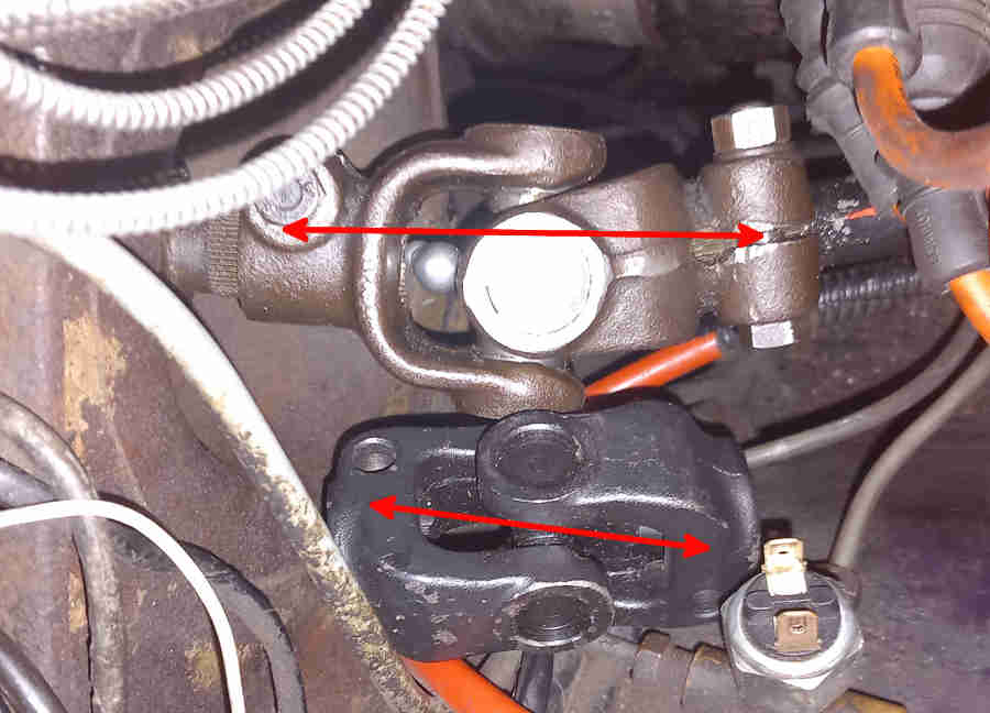 CB UJs are longer than RB - about 3.5" from clamp-bolt to clamp bolt whereas RB are about 2.5", RB are also recessed further into the bulkhead than CB, possibly because of a repositioning of the rack on the crossmember and the shaft passing through the chassis bracket for the engine mount. The CB V8 has the same crossmember as all RB cars but a unique rack and steering column with the CB UJ, with the same rack and steering wheel positions for CB and RB I don't know why it didn't have the same column, rack and UJ right through. Again I don't know if it applies to all rubber bumper cars, or just to V8s, but there is an oddity in the splined shafts that go in the UJ. On the CB roadster the column shaft has a notch for the clamp bolt meaning it can only go in the UJ in one rotational position, whereas the rack shaft has a groove all the way round meaning it can go in the UJ in any rotational position. This means the two shafts can be assembled in as many different relative positions as there are splines on the shafts. But on the V8 both column and rack shafts have the notch which means the two shafts can only ever be assembled in one relative orientation.
As far as I was aware CB cars (including V8) always used UJs that could be dismantled and just the spider, cups and needle bearings replaced with a kit originally 17H3873 now GUJ200. But most suppliers currently show a one-piece assembly with non-replaceable bearings - AHH6000. That was always the part number for the complete assembly in the Leyland Parts Catalogue, so I tend to think suppliers have adopted that number for a one-piece alternative. However Moss for example quotes AHH6000 as 'OE' and AHH6000Z as 'after-market', showing the one-piece in both cases with the OE as 'NCA', but unless the factory did start using a one-piece in the final few months of CB production that's probably a stock photo. RB cars (including V8) always had a one-piece originally 575732 now listed as GLR3084 or NRC7704.
 Both my UJs, and images of others for sale look the same, have the same distance from the centre of the spider to each clamp-bolt, which means the UJ can be fitted either way round. But this picture dating to 2017 which seems to be of a 65 MGB in Poland, so probably LHD, has the centre of the spider offset towards one clamp bolt by a significant difference. So much so that it looks like either it has been assembled from one CB yoke and one RB, or is for a completely different vehicle altogether. There is no indication in the Parts Catalogue that an LHD UJ differed from an RHD. The centre-line of the two shafts crosses at a certain point in space, and that is where the centre of the UJ must be for correct alignment. Not only is this UJ going to position the column in a different place to how it would otherwise be with a symmetrical UJ, but the centre of the spider will be in a significantly different point in space depending on which way round it is fitted to the shafts. The former situation is possible on the early and mid era columns as the outer tube can slide in the mounting brackets, and the position of the outer in those brackets positions the cowl to the steering wheel.
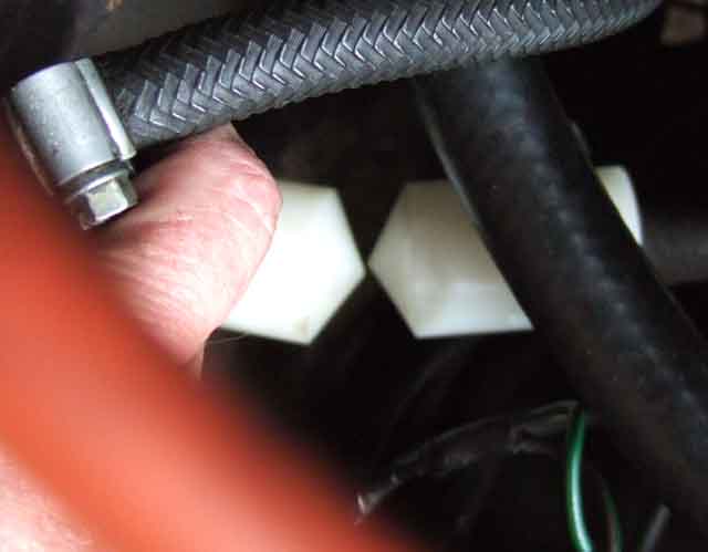
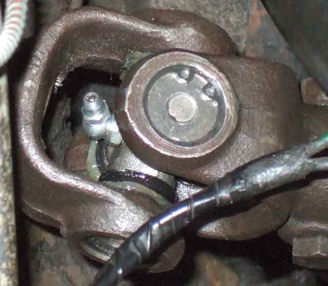 Bee's didn't originally, and probably the first one or two replacements, but since then and currently they have a grease nipple (not that annual greasing has prevented wear!). One piece UJs are sealed for life. The supplied nipple is an angled one, and is in two parts i.e. a straight nipple screwing into an angled base. With the steering turned to the appropriate position the nipple is pointing straight up, so easy to get a 6mm socket on to unscrew it from its base, which I had previously screwed in to the tapered threads so as to position the nipple between the two yokes. I have the idea of making an adapter by finding a bolt that screws into the nipple base, drilling a hole through that, cutting the head off, then drilling and tapping a for straight standard nipple to screw in to the bolt. The first brass bolt I find in my box of bits screws into the nipple base. It's a bit loose as the threads aren't the same but should be OK as I only intend to use it for greasing, replacing it with the under-sized nipple between services. The bolt has a 3BA thread, so I drill and tap the standard-sized nipple right the way through (it doesn't need a ball and spring to keep dirt out as it isn't staying on the car) making it easier to clear out swarf afterwards, and I pump a little grease through the assembled nipple and adapter stud just to make sure they are clean. Unscrew the under-sized nipple, screw in my adapter, pump grease gently until some issues from the cups, and none comes from where the adapter screws into the nipple base, which I reckon is a pretty good result! Finally unscrew the adapter and refit the under-sized nipple (which still has its ball and spring to keep dirt out of course). All I have to do now it put the adapter in a small poly bag and keep it somewhere I can find it at the next service ...
 UJ change for both CB and RB types is a fairly straightforward operation, especially for the early column as that can pulled back enough to get the UJ off and back on with the rack in-situ. For the others jack the wheels off the ground, remove the four rack bolts, and with the UJ clamp bolts removed pull it forwards about an inch or so (the wheels will toe in) and there should be enough room to get the UJs off the shafts, and the later CB column can slide up a bit to make that easier.
RB is just a straight swap from here, for CB removing the circlips and tapping the yokes knocked the cups out, but the new ones need the big vice to press them in, so no problems of them being loose next year! I then go to grease it using the supplied nipple and find it is smaller than standard, so my grease gun doesn't fit. The tapping in the UJ body is also smaller than normal so a standard nipple won't fit that either. Eventually I sort out a solution but in the meantime get on with checking the alignment of the column and rack shafts. When refitting the rack the rear bolts with spring-washers screw down into welded nuts in the brackets but the front ones go up through the cross-member brackets with spring-washers and nuts on top of the rack as there is a section of weld inside the bracket to hold the heads still with a finger-tip while tightening the nut.
December 2024: Because of the repeated issues with play developing in the spider with the original assembly I replaced the whole thing with the one-piece. I asked the MGOC if I could have an allowance against the original purchase price of the spider kit and they wrote back saying they would give me a full refund on return so I removed the spider from the yokes ... and what a pain that was! Not only did I have to use double sockets to press the first cup in each yoke out enough to grip with a vice and wrench it with both hands until the cup came free, but then I had to press the second cup back far enough to get the spider out. I tried double sockets again but this time without the cup to align it the 'cupless' spider kept tilting to one side. Eventually I had to drift the spider down with a small socket on the 'cupless' end to push the second cup into a larger socket - try holding all that lot in place with one hand while hitting it with a hammer - far enough to get the spider out. Then grasp that yoke and twist the second cup out. Managed that with one yoke but the other just would not twist, I had to put a 3/8" socket extension bar inside the cup, again a large socket underneath, and hammer it out into that. So much for tapping the edge of the yoke with a hammer while holding it in your other hand as depicted in the manual! These days close tolerance parts like this (I've heard the same with front wheel bearings) don't seem to be made to the correct tolerances any more - this was super tight but a previous kit just one year old failed the MOT because the cups were sloppy in the yokes. Took that back to John Hill's and he said it must be the yokes worn. But I keep old parts and had taken him the previous kit (failed with slop in the spider bearings), he test fitted a cup and then had to go to the workshop to get it out again! Gave me 50% off a replacement. At least I shouldn't have to go through that palaver again - replacing the one-piece is a doddle by comparison, I just hope the one I have bought for Bee is as good as the one that came to me on Vee.
August 2024: At the MOT I again get an advisory for worn inner rack joints, and there is again slop in the column UJ after barely 1000 miles. This time I opt for the one-piece replacement (similar to the RB UJ) instead of the spider kit, but replacement with that is by no means straight-forward as it is not a direct replacement!
November 2023: As part of a long saga involving steering racks I changed the column UJ yet again - for the fifth time each time with them showing play - not that it had any effect on the steering column problem, that seems to have been down to pinion shimming!
This time was more of a struggle than I remember on the previous occasions. It needed the cups pressed through with double sockets (small one on the back of one cup, large one round the other one being pressed out) in a large vice as far as they would go i.e. until the spider is pressed up against the inside face of the spider, then the few mm of the cup that protruded gripped tightly in the vice while I twisted the yoke back and fore lifting all the time - not easy. Then the spider and the other cup has to be pressed the other way through the yoke, again with double sockets, the small one this time pressing on the end of the spider, again to expose a few mm of cup, remove the spider, grip the cup in a vice and twist out as before.
Reassembly also needs a large vice - if there is a grease nipple fit this first. Get the first cup started in one side of the yoke - no sockets needed but make sure it is 'square' to the hole before applying loads of force. Then once part-way in feed one end of the spider into the 'empty' side of the yoke and swivel the other end of the spider over the partially fitted cup and insert it being careful not to dislodge any needles, but they should be held in position with pre-applied grease. Then fit the other cup, again no sockets and being careful it is 'square', and especially careful that both ends of the spider are fitted into the cup without dislodging any needles. Once the spider is in both cups clamp up to put both cup bases flush with the yoke. Then another small socket on the back of each cup in turn to press it in just enough to fit the circlips.
Circlips were another issue - the existing ones seemed too big for the hole, circlip pliers wouldn't lift them straight out so I had to use a combination of pliers and a very small screwdriver to lift one end free of the hole then pull on that to get the rest out. By contrast if anything the new circlips are a bit smaller than I would like, floating in the groove much more, with only a small overlap when pushed to each extremity. Next time will be a one-piece!
October 2018: Returning from The Beacons Run in Bee 'at speed' I'm aware of a slight vibration from the steering wheel - but nowhere near as bad as when the V8 wheels were unbalanced - and investigating shows there is slop in the UJ - again, after six years and just 10k, and despite this one having a grease-nipple I've lubricated each year, so yet another replacement needed. By contrast the different design on Vee - despite 100k with me quite a few of which with significant wheel imbalance and wobble - is the one that came with the car. Replacements can be very variable in price - anything from £8 to £16 from the usual suspects plus eBay. Delivery can be anything from £0 to £11 with some sources having a low item price but high delivery cost, so you need to look at the total price when making a decision. Before replacing that (the fourth replacement!) I got the front wheel balance checked.
August 2012: Bee had advisories on both track-rod ends this year. Having a quick look the boots had split on both, and the pin on one was loose in the body so I'm surprised it wasn't a fail. But while checking those I became aware of slop in the column UJ (again!) and that is usually a fail. This will be the third replacement, the first (July 1997) failing at the next MOT as the cups were loose in the yokes, but I got a 50% refund on that one against a replacement. The second replacement (July 1998) lasted about eight years and 20k, this one (bought June 2006) six years and 12k. Thinking it could be column and rack alignment, my previous attempts being done with wire pointers as above, and having recently found Moss UK have the alignment gauges, I get the UJ, track-rod ends and gauges from Moss.
Alignment: July 2008
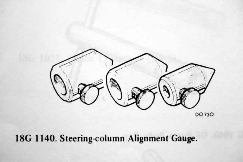 The objective is to get the centre-line of the rack shaft crossing the centre-line of the column shaft at the exact centre of the UJ. It is achieved primarily by positioning of the steering column but may also need shims at one or more rack to cross-member mounting points. It is necessary because the rack and column shafts sit at different angles in both the vertical and horizontal planes as well as manufacturing tolerances in the bodyshell and crossmember. The factory used this tool (click thumbnail), note that the different bores shown were probably because it was a standard tool across a range of BL vehicles. Highly unlikely to be available now (until replicas available from Moss), so how do we replicate it? Personally I wrapped some stiff wire around the end of each shaft, with the tip of each wire at a point in space equal to where the centre of the UJ would be when fitted to that shaft. You can get the tip exactly on the centre line by rotating each shaft in turn, if you get any wobble of the tip it isn't aligned, so tweak it until it is stable. Then it is a matter of fitting shims and adjusting the column as required to get the two tips just touching, which is very fiddly and could be quite a long process of trial and error, others have said they used blobs of Blu-Tak or similar. The problem with both of these is that it is very easy to knock the tip of the wire or Blu-Tak off-centre as well as length. Some have said they loosely fit the rack, connect up the UJ, then measure the gaps between the rack casing and the crossmember and fit shims accordingly. Personally I don't think that is good enough on its own as the weight of the rack will be hanging on the UJ to some extent, although it is probably good enough to get a starting point for shims, and trial and error with pointers after that for fine adjustment. Update January 2010: Even worse is a method I've seen where someone turns the steering wheel back and fore while someone else tightens up each rack bolt bit by bit, till the steering wheel binds, then that bolt is slackened a bit, a section snipped out of a washer so it can be slid on the bolt, and that bolt tightened. That is so crude, the UJ will surely start binding way before you can feel any resistance at the steering wheel, hence still be binding when it is backed off a bit and the washer tightened. Besides which the washers that were shown were way thicker than any shim I have seen. Definitely from the "If it isn't bodged it won't work" school of engineering.
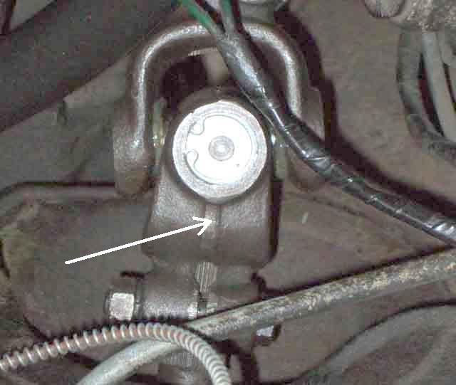
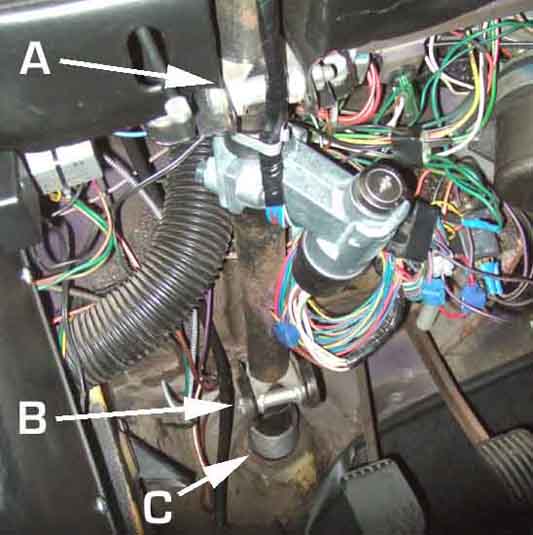 The early and intermediate columns (all non-North American chrome bumper cars including (updated June 2026) V8s) have two U-brackets under the dash that grip the column outer setting its fore and aft position, the clamps slide up and down in the dash brackets to set the vertical position of the column inner for UJ alignment. Additionally the bracket at the bulkhead end offers horizontal adjustment for UJ alignment when its two bolts on top of the heater shelf are slackened. Rotating the column in the brackets sets the indicator stalk position, and if the column is slid through the clamps (Bee's are tight!) you will change the position of the column cowl relative to the steering wheel.
 The later energy absorbing column (V8 and RB) has one bracket under the dash with three bolts going into caged nuts and the bottom of the outer tube has a loose plate with three bolts screwing it into the bulkhead. It's been said that this bottom plate and its bolts are to align the column but that is not the case, they simply clamp the loose plate and a gasket to the bulkhead - once the column has been correctly aligned - and are solely to seal the body aperture against water, noise and fumes ingress. The three upper bolts and caged nuts allow horizontal adjustment, and spacers on one or more of those bolts between column and body brackets set vertical alignment. Until the three dash bracket bolts are tightened the UJ end of the column can move horizontally and vertically relative to the rack and is not aligned, the three toe-board bolts are only tightened when UJ alignment has been achieved. For this column the inner is fixed relative to the outer so it's the rack and the UJ that determine the fore and aft position of the whole column relative to the dashboard brackets, the cowl automatically takes up the correct position relative to the wheel, a small amount of variation in the angles of the column stalks depends on what (if any) shims have been used on the upper bolts.
As far as using gauges goes my Haynes says that the rack and column should be fitted before installing the alignment gauges. That can be done with CB columns as the column inner can be slid up the outer enough to fit and remove the (Moss at least) gauges. With the early column the inner can be slid back far enough to enable the UJ to be fitted and removed as well, but with the late CB column with steering lock (even when disengaged with the key) the inner does not slide back far enough for the UJ, only the gauges. Note that if the later CB column inner with wheel fitted slides forwards with the UJ removed it can bend the horn brush away from the wheel so check horn operation on completion.
With the later full energy-absorbing column the inner cannot be moved relative to the outer at all so for both the late CB and the RB the rack has to be pulled forwards to remove/fit the UJ, and for the RB you cannot even fit and remove the gauges without doing that. My Leyland Workshop Manual says to fit the rack after the column, and after the gauges have been fitted. But because the rack shaft passes through a hole in the right-hand engine mount the gauge cannot be fitted onto the rack shaft until it has been passed through the engine mount. If you have had the column off then it is easier to fit that gauge before the column is reinstalled because the gauge is in a recess in the bulkhead and more difficult to get at than with the earlier columns, but it still has to be removed with the column fully fitted. Towards the end of the process it tells you to replace the gauges with the UJ, then fully tighten the two upper bolts, then measure the gap at the third bolt, and fit shims accordingly. This makes no sense to me. Better to align, fitting shims as required to the third bolt and fully tightening all three to get the correct alignment while the gauges are still on the shafts. Additionally at the end of the process i.e. with the gauges replaced by the UJ it tells you tighten the two upper bolts then measure the gap at the third bolt and fit shims accordingly. This makes no sense to me, as the gauge of the correct size would have to be gripped by almost the same tension as the final shims which is 12-17 ft lb as you were sliding it in and out. Better to align, fitting shims as required to the third bolt and tightening all three to get the correct alignment while the gauges are still on the shafts. More long-winded certainly, but it seems more accurate to me. Note that there need to be spacers on the two upper bolts or the ignition switch will be too close to the lower edge of the binnacle, spacers/shims are fitted to the lower bolt as required to get the correct up and down alignment of the UJ.
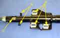
The rack gauge must be positioned correctly on the shaft by use of its clamping screw in the centre of the notch or groove. The Moss gauges have two holes for the screw - the one nearest the open end is correct for the UJ with the replaceable spider (early and mid column), the one nearest the tip for the later one-piece UJ (later column). For early and late CB columns the column gauge need not be clamped onto the shaft as it only has to meet the tip of the rack gauge and the inners slide freely for the fine positioning needed to get the column clamp bolt inserted. Adjust the column position and the rack shims as above to get the correct alignment. With the V8 and RB column the inner column cannot slide in the outer and so that gauge must have its screw tightened into the notch as well, and the column must be loose on it's three mounting bolts to get the correct fore and aft and lateral position, adding and removing spacers and shims as needed to both column bolts and rack bolts to get the correct vertical alignment.
IMPORTANT: For the reasons given above with all columns if you remove the column or slacken its clamp bolts even if you haven't altered the rack you will need to recheck the alignment before retightening the column clamp bolts. Therefore for final fitting of the UJ the column has to be positioned and any rack mount shims determined with the gauges on the shafts, then the rack has to be pulled forwards to remove the gauges and fit the UJ.
Note that even with the front wheels on the ground with the four rack bolts removed, leaving the track-rod ends attached to the steering arms, as you pull the rack forwards to allow you to remove the gauges and fit the UJ the wheels will simply toe-in towards each other and gives enough of a gap to fit the UJ.
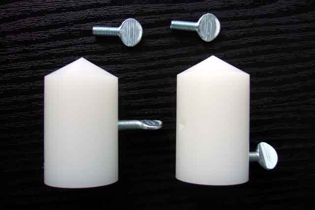
Some time later I came across a web page by Simon Jansen in New Zealand who had fabricated his own alignment tool and gave the dimensions he used, see here and scroll down to January 2006. This topic comes up on mail lists and BBs from time to time and I had posted links to Simon's site. Recently someone came back querying the 29mm dimension from the centre of the notch in the shafts and the tip of the tool, saying his was more like 33mm. I passed this on to Simon, and he said it was possible as his car was a mish-mash of components as it was a conversion from rubber bumper to chrome and from LHD to RHD. I measured a new RB V8 UJ as carefully as I could and also came up with 33mm, with 45mm for my chrome bumper roadster (measured on car) and posted this as a warning with the link I already had on this site to Simon's page.
Some time after that Kelvin Dodd of Moss US posted this link to a replica tool available from Moss. It's curious that it seems to come with two sets of screws, as it would need two sets of holes to be suitable for both chrome and rubber bumper cars, which would need only one set of screws. I asked Kelvin if could confirm whether there were one or two sets of holes, and what the distances to the tips were. He came back with the information expressed slightly differently as being an overall length of 2.11", one hole 0.336" from the open end, and another hole 0.936" from the open end. The bore is 0.744+-0.005/0.002" or 18.9mm (slightly smaller than Simon's 19.3mm), and the hole depth is 1.70". Converting this to distance from the tip and millimetres I get 1.174" or 29.82mm for one hole and 1.764" or 44.8mm for the other, and this is where it gets curious. The Moss 29.82mm is pretty close to Simon's 29mm, and the Moss 44.8mm is very close to the 45mm I measured on my CB roadster. However my RB V8 UJ measures 33mm, which is the same measurement that the person who queried Simon's dimension in the first place, and looking in the Parts Catalogue there are only two part numbers for UJs for all models, years and markets i.e. one for CB and one for RB.
 So I've re-measured my new RB V8 UJ more carefully, and still get around 1.2415" which equates to 31.5mm, so the Moss 1.174" or 29.82mm remains a mystery (Simon's original 29mm less so as his car is much modified). If making a tool for yourself you will need to check your UJ dimensions very carefully.
Update March 2010: Just been made aware of the identical alignment tool at Moss Europe. The good news is that it is only £7.65 (£16.50 in Sep 2017) as opposed to $24.95 when the exchange rate is 1.5 i.e. $12 or £16! The bad news is that they insist on you ordering at least £10 of parts, before they tell you the shipping costs (subsequently that restriction was removed).
Update August 2010:
 I get the Moss gauges with a replacement UJ and track-rod ends, so measure them myself, at 44.58 for the CB and 30mm for the RB and all V8s. The latter UJ is 31.5mm, and as that column has a fixed shaft this means that a small gap has to be left between the tips otherwise you cannot get both clamp bolts through the UJ. Doesn't matter for the earlier columns as the inner slides in and out to suit. As I've got to
change the steering column UJ, and the rack has to be pulled forward for that, it's a good opportunity to check the alignment at the same time (which is why I bought the gauges with the UJ ...).
I get the Moss gauges with a replacement UJ and track-rod ends, so measure them myself, at 44.58 for the CB and 30mm for the RB and all V8s. The latter UJ is 31.5mm, and as that column has a fixed shaft this means that a small gap has to be left between the tips otherwise you cannot get both clamp bolts through the UJ. Doesn't matter for the earlier columns as the inner slides in and out to suit. As I've got to
change the steering column UJ, and the rack has to be pulled forward for that, it's a good opportunity to check the alignment at the same time (which is why I bought the gauges with the UJ ...).
Compare the gauge to the UJ, position the tip in line with the centre of the UJ, and see which hole in the gauge lines up with the clamp bolt hole in the UJ, and put the clamp screws in those holes. Note that each part of the Moss gauge seems to be a couple of milli-metres shorter than my rubber bumper UJ (not so the chrome bumper), so bear this in mind when doing the alignment i.e. leave a couple of mil between the points or you may not be able to get both UJ clamp bolts in right at the end (alternatively, fit the UJ first, nip up the column bolts to get the correct in and out adjustment, then pull the rack forwards to replace the UJ with the gauges and note the gap between the tips, if any. When you have corrected the column and rack shimming for horizontal and vertical alignment make sure you end up with that same in and out gap). Note that the screws must go into the centre of the notch/groove in the shafts, not onto the splined portion.
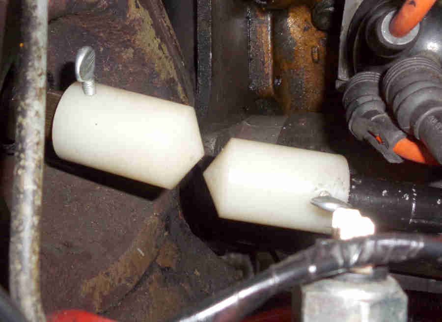
 The gauges are a nice snug fit on the shafts which is good, and one thumbscrew in each gauge going into the shaft groove holds them firm. The tips are about 1/8" out, part horizontal and part vertical, which could have contributed to UJ wear, but there is some up and down and side to side play in each shaft so the end result would have been not much by way of sideways forces on the UJ. I'll need to adjust the sideways misalignment at the column mountings, so I opt for seeing if I can get the vertical alignment corrected there as well, rather than fiddling with shims at the rack. This style of collapsible (not the later full energy-absorbing) column used on UK 72 and 73 models is supported by two body brackets, one up by the dash and another one further down under the shelf.
 Both are slotted so each mounting can move up or down independently giving quite a large change in vertical position of the UJ end of the column shaft. I find the top can go up just a little bit and the bottom down, which puts the gauge pointers in perfect vertical alignment.
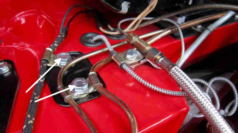 For horizontal alignment the lower bracket has two bolts up through the heater shelf (with support clips for brake and clutch pipes and harness) and with the nuts slackened the bracket and hence the UJ end of the column can be moved from side to side. With this column the inner can slide up and down freely so you need to pull the wheel up a bit while moving the column, as if the gauge points overlap they will jam and possibly get damaged. Then it's unbolt the rack again and pull it forwards as before to remove the gauges and fit the UJ, lining up the splines by eyeballing the front and rear tyres each side to get to get the steering straight, then fitting the UJ with the wheel in the straight-ahead position, and finally bolt the rack back down. The UJ only attaches to the column shaft in one position as the cut-out for the clamp bolt is cut straight across, but the rack shaft is cut all the way round (oddly the V8 only has notches in both shafts). Really I should have put a paint-mark on the rack-shaft in line with the slot in the clamp before removal, but as I've got to change the track-rod ends as well and then get the alignment checked, it'll come straight in the end.
April 2023:
 For Bee's new rack none of the column adjustments would get the tips in line - rack shaft too low - so the upper mountings to the cross-member had to be shimmed.
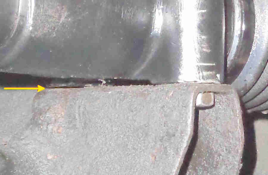 The other potential issue is that both mounting points on the rack may not sit square to the brackets on the cross-member, and that proved to be the case, the upper one on the near-side had a 12 thou gap when the other three bolts were nipped up, so that side is going to need a spacer 12 thou thicker than the upper off-side. In the end I put a 63 thou spacer on the off-side upper and an 85 thou on the upper near-side. Getting them in was a fiddle as neither of them can be fitted with fingers. In the end I did them by lifting the rack up with one hand while I slid them into position from underneath using an open-ended spanner to guide them. I had bolts in position and protruding from the mounting, pushed the spacer up to touch the threaded end of the bolt, then lifted the bolt and pulled the rack forwards a bit to put the bolt over the hole in the spacer (without knocking it out of position ...), lower the bolt into the spacer, then wiggled the rack, bolt and spacer about until the bolt was aligned with the threaded hole in the cross-member bracket. Bolts with a ground point would have been easier ... and had spacers been needed at the lower bolts then easier still!
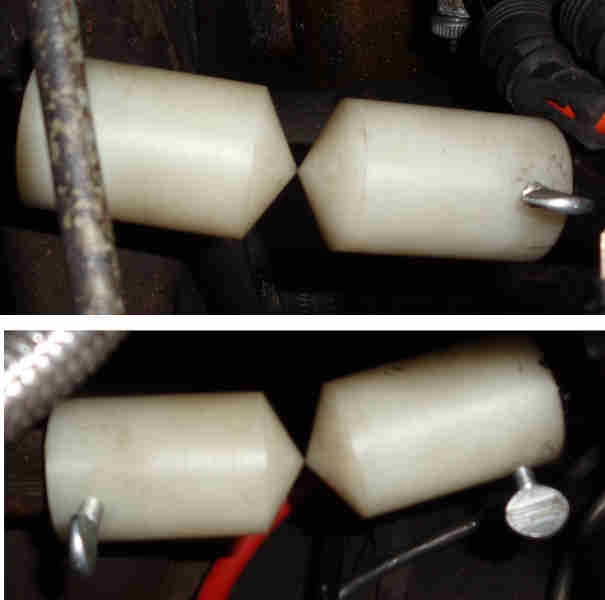 They raised the rack shaft pointer above the column pointer, but I had put that in its lowest position to try and meet the rack pointer before shimming, and it was a simple job to raise the column pointer using the two column brackets.
One-piece UJ for CB cars: September 2024:
 The original CB assembly of yokes plus replaceable spider part number AHH6000 hasn't been available for a long time (other than used although spider kits are available) but suppliers are showing that part number with a suffix letter - e.g. AHH6000Z - which usually indicates it is a copy part. However all the ones I have seen are a one-piece UJ similar to the RB item. It is not an exact replacement for the original CB assembly but a 'near equivalent' being 4" overall instead of 4 3/8" and having different pinch-bolt centres at 3 1/4" instead of about 3 1/2". In theory that shouldn't cause a huge problem with the early and intermediate steering columns where the inner is free to move up and down inside the outer tube to a certain extent - as my 73 roadster does. The CB V8 used a unique column (BHH806) and rack (BHH868) both NLA and Moss indicates the same UJ as 4-cylinder cars (AHH6000). The later full energy absorbing columns used on all RB cars is different in that the inner is in a fixed position in the outer and used a one-piece UJ (GLR3084 still available). North American Mk2 CB had different columns at various times using AHH6000 on CB and a different unique UJ on RB.
Whilst the one-piece does avoid the fiddle of getting the spider and cups out of the yokes, and refitting them, they are about seven-times the price (I have seem them even higher at £120) of the repair kit for the repairable version. OTOH I have replaced Bee's five times now in 34 years, lasting less and less each time despite being very careful with alignment! Although not a source of MOT problems recently (the 'original' (to me) and first replacement were) there have been advisories of wear in Bee's rack for about three years, including a replacement only a few months old. So I'm wondering if it is the UJ they are picking up and in November 2023 replaced it yet again and on a retest it made no difference. Not only that but less than a year and 1500 miles later that one is also showing play, and the rack inner joints again get an advisory! Ironically, despite doing over 100k and several years of that with intractable steering wheel vibration Vee is still on the same one-piece UJ she came to me with - and quite possibly the original at 230k! Because of the vibration I expected problems with that UJ, so bought a new one ready for if and when I got the vibration fixed, which I did eventually but the UJ still shows no play at all so it sits 'on the shelf'.
Used with the CB column where the inner moves longitudinally in the outer the steering wheel will take up a position about 1/4" further away from the driver which has two knock-on effects: The first is that the back of the wheel will move closer to the cowl which has a fixed position determined by the indicator switch which sits in a location notch in the column outer tube, and the other is that the steering lock may no longer engage. For the first the outer and hence the cowl should slide through the under-dash brackets to suit (which will correct the steering lock), but slackening those may alter the original alignment. Alignment will be altered by the shorter UJ anyway by the column shaft having to be angled down to meet the rack shaft, so you will need to go through the alignment process in any event.
 But the gauges are designed for a specific distance between the centre of the spider and the pinch-bolt so that is another issue and each half of the tool will be 1/8" too long. On early and intermediate columns the shaft moves back and fore independently so in theory it's half of the gauge does not need to be modified. The rack half will as that shaft is in a fixed position (longitudinally, cross-member shims only alter the angle), but I found both halves needed to be modified as the gauges need to be fitted while setting the relationship of the wheel to the cowl, as well as for fine-tuning for the UJ.
The only person I am aware of to have used this UJ chose to 'create a new pinch-bolt recess in the column using the new UJ as a jig'. Either both shafts would need new pinch-bolt locations to put the centre of the new UJ in the same position as before to maintain alignment, but CB (at least) 4-cylinder rack shafts have a groove all the way round so that can't be modified as it would widen the groove by 1/8" meaning with the clamp bolt inserted the UJ would be able to move on the shaft. The column shaft just has a notch so in theory by inserting the shaft to the UJ such that the notch no longer lines up with the pinch bolt hole I can imagine drilling through the pinch-bolt holes of the new UJ to create a new notch. But there are two things to watch out for because the centre of the UJ is 1/8" closer to the rack. Firstly the new notch in the column shaft would have to be 1/4" closer to the end of the shaft and with the intermediate shaft being able to move in and out of the outer it would have to be clamped in the correct position in some way while you are drilling to maintain the relationship of the steering wheel to the cowl to avoid rubbing or a gap. Secondly because the rack shaft is angled downwards the centre of the new UJ will be lower than the old one so the alignment would have to be checked with gauges to see if the column needs to be moved in its clamps. But I didn't fancy drilling the column shaft anyway.
Installation: December 2024
 With the modified gauges fitted to the shafts and the tips touching the wheel had moved 1/4" closer to the cowl as expected. It would have rubbed on it had I not already removed the cowl and the steering wheel to allow the column shaft to move down to meet the rack shaft. In theory slackening the upper and lower column clamps should have allowed me to slide the outer through them 1/4" closer to the bulkhead, but it would not move even when fully slackened. I wondered if the U-clamps on the outer were keyed to it in some way, so it would have to come off. Grub screw for the ignition switch was the easiest way to disconnect that, and the indicator switch removed. Removed the column gauge and the clamp bolts and the column was out in not much more time that it took to write it. On the bench the U-clamps were a tight fit on the outer but it was easy to tap then up the outer the required 1/4" as the original position was clearly visible, and it could go back in. Note that the rotational position of the outer in the U-clamps will affect the angle of the column stalk. The U-clamps are a tight fit in the body and dashboard brackets, took a bit of fiddling to get the bolts through, which was why the outer wouldn't slide in-situ. Barely nip them up so the column shaft can be aligned to the rack shaft. Refit the gauges, refit the rack to the cross-member fully tightening all four bolts to ensure the rack shaft is in its final position. Tweak the column clamps in the brackets to get the tips of the gauges touching on both vertical and horizontal orientations. Only up and down movement was needed, I had corrected the horizontal alignment when this rack was fitted. Fully tighten the column clamp bolts and recheck as the column may have moved.
 Unbolt the rack and pull it forwards to remove the gauges, and fit the new UJ. Refit the rack bolts and tighten the UJ clamp bolts. Then it should just be a matter of refitting the ignition switch to the lock with its fiddly grub screw, the indicator switch, steering wheel, horn pencil and horn push. Check all electrical functions - ignition, cranking, indicators for lights and cancelling, headlights dip, main and flash, and horn, and finally refit the cowl.
The biggest part of the job is repeatedly getting underneath to unbolt and bolt up the rack to remove the old UJ and fit the gauges then again to remove the gauges and refit the new UJ, which has to be done in any event. By contrast removal and replacement of the column was quicker and easier than getting the old spider out and fitting the new one had been on previous occasions. Time will tell if this one-piece lasts any longer than the five spiders. Detectable play in-situ could be seen and felt, off the car there was none with it in my fingers although the two halves are floppy, but with one half clamped in a vice and the other half held with grips there was the same play. But then again, how would a DIY-er get it assembled into the yokes in a domestic garage if there were no play? By contrast the one-piece assembled in a factory is a different matter. That was stiff off-car and has no play on-car ... but waggling the steering wheel reveals play further down i.e. the rack or beyond! I know the TREs are good as the pins were very stiff to move while they were unbolted from the steering arms, and the steering arms were supporting themselves when the TREs were unbolted which means the inner joints are being gripped, so the rack pinion will be the next investigation, and after that king-pins. I may be going overboard but Vee has never had that advisory with all original (to me) components, Bee didn't before 2021 and since then it has been every year despite two different racks and at least two column UJs.
1st January 2025: Did I say no play on car? When I removed the shims from the rack and bolted the cover back down there was just detectable play in the UJ! Less than with the rack set correctly, so that will just have to stay. Next test will be to redo the MOT test that shows play in the inner rack joints but with the shims removed and cover bolted down, and if that shows none then it can't be the inner joints, so remaining play can only be the pinion. And having fitted two rebuilt racks both the same that will have to stay as well, advisories or not! If play still present with the pinion bolted down it could be the inner joints, but they are 'tight' enough to support the TREs easily, but could also be the TREs, king-pin, A-arms, or wheel bearings. It all depends on whether anything can be seen/felt to move as well as the sound, which could be coming from anywhere.
October 2025: Determined to try and get to the bottom of this 'worn inner rack joints' issue I have another go ... and along the way realise that the steering lock no longer engages! Vee's never engaged on the road, the only time it did so was when I was doing something with rack or column, but not when it was back on the car again. As this one-piece UJ involved moving the position of the inner because of the different UJ (which has the slot for the lock tongue) and the outer (which has the lock) to retain the relationship between steering wheel and column cowl I can only assume that I have changed the longitudinal relationship of the two. No matter, it was always a pain when rolling the car in the garage that a slight movement of the wheel was enough to engage the lock and I'd have to go and get the keys to unlock it again.