
Dash Fitting Removal from Case The Odometer Oil Contamination
Anthony Rhodes has produced a useful document 'Repairing Jaeger and Smiths Speedometers' as typically used in MGBs. This is the 2002 version (there is also a 2000), one source of which indicates there is a 2004 version in the pipeline. However as I only came across that reference in 2014 it seems that it was never produced for some reason. It also does not go into much detail on the odometers, hence this page, which should be read in conjunction with his document.
Speedy Cables is often mentioned as a source of speedo repairs, but there have been complaints of these taking several weeks.
JDO Instruments offers a 48 hour turn round which has been verified by members of the MGOC MGB Technical forum.
80mm V8/RB
Reassembly to case
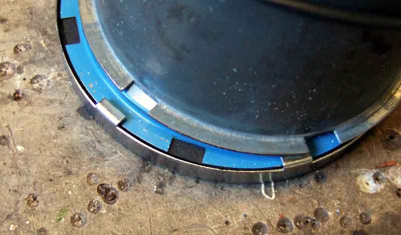
 The bezel has six (on the 4" instruments) tabs that fit over a flange around the case. There are six corresponding cut-outs (arrowed) in the flange, so the bezel needs to be twisted round until the tabs line-up with the cut-outs. If it's never been off before it will probably be stuck fast, but try first. Lever each of the tabs back a little at a time then try twisting, until it comes off. Only bend back the tabs the minimum amount, or it will distort the side of the bezel and be visible when fitted. The only seal is between the bezel and the glass, so it shouldn't be that making it difficult to remove. The glass should be stuck to the bezel seal so come away with the bezel, the edge reflector may also come away or be left inside the case. In the latter case (ho ho) it should hook out easily enough.
Getting the mechanism out of the case in two speedos I have is nothing like as simple as Rhodes describes. He says:
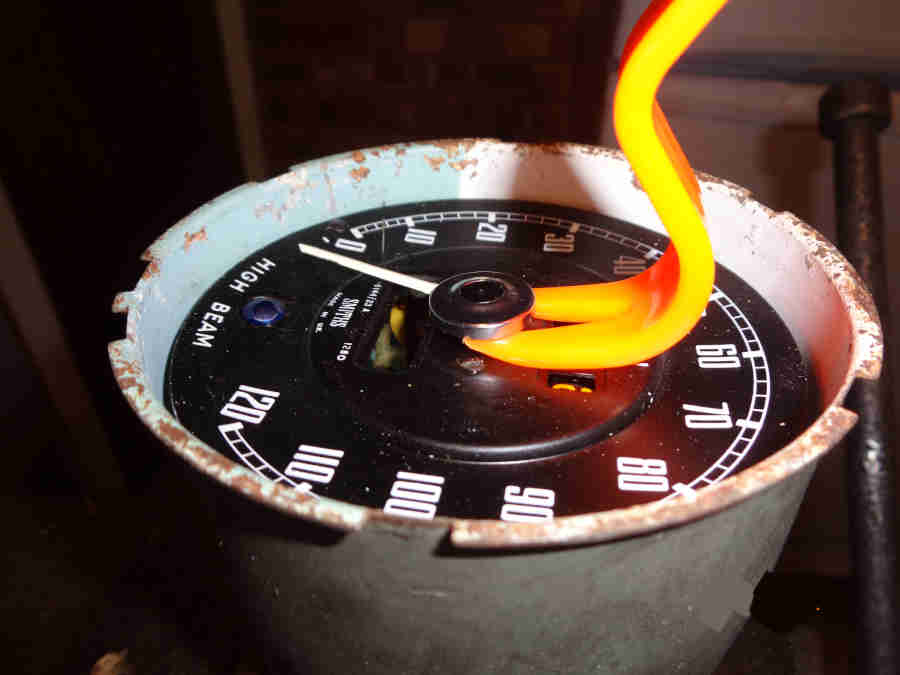
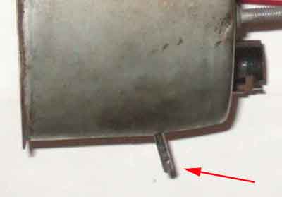 For a start on mine there is a roll-pin connecting the reset knob to the spindle that has to be pressed out, but more importantly the spindle still projects through the case by about 3/4", which is a lot more than he shows for Triumph speedos. It doesn't push up into the case more than a fraction, and that holds the lower part of the mechanism back in the case, and only the top tilts forwards. This means the threaded boss for the cable tilts, which jams in the hole in the back of the case, even if the rubber gasket is pushed out of the way. The dial also tilts, and the lower edge of that fouls the lower half of the case. You need to remove the pointer then the dial in order to get the guts out, but as Rhodes says MG pointers are tighter on the spindles than Triumph speedos! He gives a method that works easily enough once the mechanism is out, but that's no help at this stage. The only way I have been able to do it - being nervous about levering on the pointer too much in case it damaged it or the spindle - is by removing the screws from the face, inverting the speedo so that the dial drops down onto the back of the pointer, then as the mechanism starts tilting in the case, ease the lower edge of the dial over the edge of the case. There is no clearance, so even this method requires some force, raising the possibility of damage to dial, pointer or spindle. The first one I did came out that way, but when trying to reverse the process to put it back in the case, the pointer pinged off! I was sure I had broken the spindle, but fortunately it had only become detached, and refitting it in the correct place was easy enough. You will probably need to push the gasket out of the screw holes so that it comes out with the mechanism, as getting that off the threaded input boss while the mechanism is half way out isn't easy.
Once out of the case his description of removing the pointer: "Remove the pointer by gently turning the drag cup until the pointer is at 60 mph. Then gently hold the drag cup in place. Hold the pointer by the hub and pull and twist the pointer until it pops free of the spindle" did work for me, but I still feared bending or breaking the spindle. Then removing the dial exposes all the works.
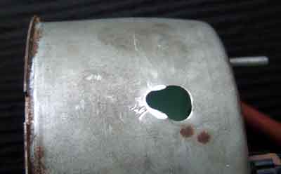 The second time I opened up Bee's I didn't want to force it, so extended the hole that the reset spindle protrudes through into a slot, and that gave just enough forwards movement of the mechanism so the dial cleared the case while still attached to the frame. I cut it roughly with a pair of tin-snips with the mechanism still fitted, then cleaned it up after removal. This allows just enough additional forward movement for the dial to clear the edge of the case while still screwed to the mechanism. The felt washer still covers the extended hole, but you could always fit a bigger piece.
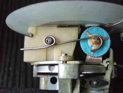
However Guy Renou removed the pointer with the mechanism still screwed into the case by putting a cloth over the dial for protection then using the curved tines of a table fork to carefully lever it off.
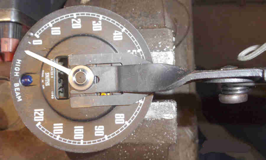
But this trim removal tool works a treat, with the tips under the pointer as here it can be gently levered off:
The pliers-type can also be used but the screws holding the mechanism into the case have to be removed so the guts can be lifted high enough to get the tool underneath:
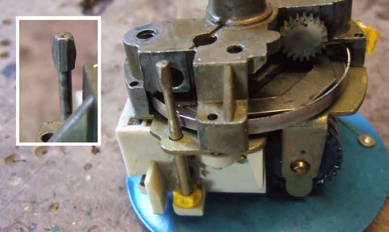
With that done, and the dial removed, you can remove the small circlip from the upper part of trip reset spindle which allows that to be removed - watch for the little cog at the top - then the mechanism is easily removed from the case. That also means the lower half of the reset shaft doesn't need to be detached first and the roll-pin lost!
Once you have the speedo in your hand it is simplicity itself to remove the innards from the case - twist the bezel to line the tabs up with the case slots to remove bezel and glass. The blue shield can be removed from the bezel in the same way to access the glass:
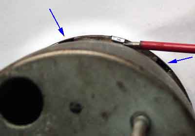
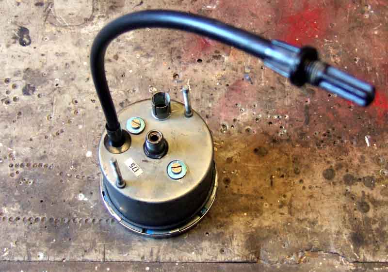
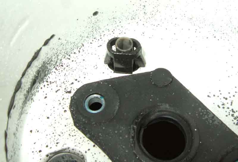
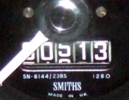
Remove the two screws on the back. The trip reset cable is attached to the case back and has a socket for the shaft on the mechanism (shaped similar to a 'two in one' screwdriver) which disconnects as you slide the mechanism out of the case. Note Vee's 960 TPM speedo has a white worm gear operated by the worm screw on the input shaft, as opposed to the red one on Bee's 1280 TPM:
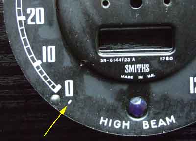 Refit the gasket to the case, and put the mechanism back in the case without dial or pointer. Fit the dial, then the pointer. There is a mark on the dial (line on MGB, spot on Triumph apparently) just below the zero, and this is the zero mph datum mark for the pointer. Fit the pointer over this mark, then depress the stop (it will go straight into the dial against spring pressure) and move the pointer past it. How accurate this datum is I didn't know, particularly as the small amount of friction between the pointer spindle and its bearings means that the pointer is stable either side of the mark to a certain extent. Rhodes describes a very complicated way of checking the calibration, but all I did when I accidentally pinged the pointer off when refitting the mechanism to the case with dial and pointer already fitted, was to raise one rear wheel, run the engine at 1667rpm (for my 4-synch) in straight top, and popped the pointer back on directly over the 30mph mark! I subsequently checked it against road-side speed indicators, and it was spot-on, maybe I was just lucky. The tachometer is easy to check against an external device, of course. A slightly lower rpm - say 1620 - will give about a 1mph over-read at 30mph for both 3-synch and 4-synch boxes. A sat-nav will probably also give you a true speed reading to check the speedo against. This time having already fitted the pointer using the datum, I checked it the same way as previously. It came out either spot-on, or maybe under-reading by a fraction, but I'll leave it as it is until I get the chance to check it against a roadside sign or someone else's sat-nav.
There is some kind of seal between the glass and the bezel (bezel seal), completely hardened and cracked on both speedos, as well as a square-section O-ring between the case and the dashboard (dash seal). The only two places I have found that stock seals such as these in the UK are Holden and AES.
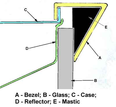
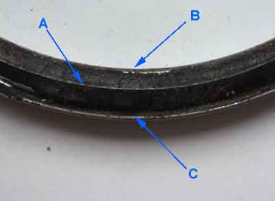 As far as the bezel seals go Holden don't list them. AES list a flat seal for an 88mm gauge but not for other sizes. They do list a sponge cord seal which you cut to length, in 3mm and 4mm thicknesses, 4mm being recommended for 'larger' gauges. However MGB 'half Vee' bezels have a triangular profile facing the glass. The inner edge of the bezel (B) rests right on the glass, but at the outer edge (C) there is about 7mm of depth available. The diameter of the glass is such that it fits inside the case, except that it rests on the 'reflector ring' (a pressed metal ring that is black on the front and white on the black, which reflects light from the internal bulb onto the dial). This means that the edge of the glass (A) is less than half-way between the inner and outer edges of the bezel. Even the 4mm sponge cord would just sit loosely in the gap between the edge of the glass and the outer edge of the bezel, I can't see how it would be compressed to form a seal. If it were glued close to the inner edge of the bezel, such that it was under the glass, then it would form a seal, but because of the slope of the bezel from the inner to the outer edges there would be significant pressure trying to push the seal towards the outer edge, and out from under the glass, and I can't see it staying in place.
 AES also have a 4" under bezel seal, which I'm assuming goes between the glass and the bezel. This looks to be round profile like the cord seal, but without knowing the diameter or thickness this may be no better than the cord seal. If it sat just inside the outer edge of the bezel it would be useless. If it sat just outside the inner edge, then initially it would be far too thick to allow the tabs on the bezel to fit over the case rim, unless in the process of fitting it was squeezed down the slope of the bezel towards the outer edge of the glass. I've seen a statement that the original bezel seal is a dum-dum type of substance i.e. a kind of non-setting mastic. There are many mastic/butyl strip/bead products around, but most end up being Ł15 for 8 metres which is a daft prospect for a couple of gauges. A possibility is this Black Tack at Ł5 although at 19mm wide it would need cutting into narrower strips.
The smaller gauges may just have a flat 'fibre' seal between the glass and the dial, extending past the bezel as a screen to block light from inside the gauge being projected towards the driver.
For O-ring dash seals Holden list 100mm (4"), 80mm and 52mm (2"). AES sell 4" square section and 2" square section but not the 80mm as far as I can see.
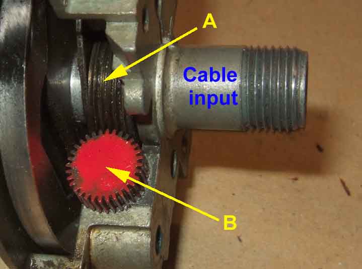
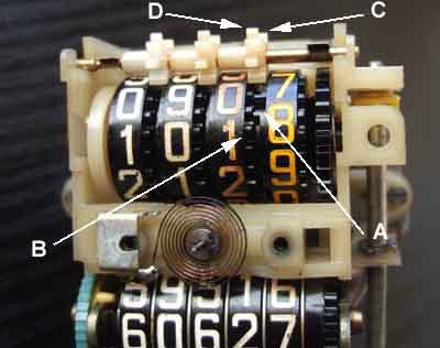
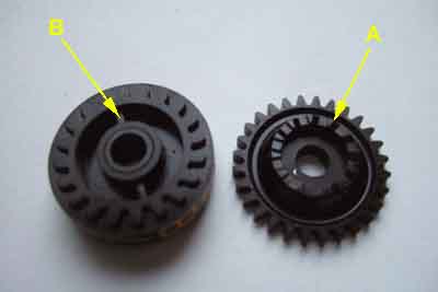
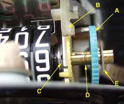
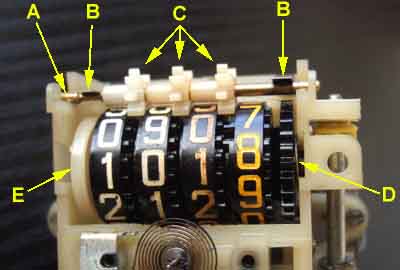
The input shaft driven by the cable has a worm screw (A), with a worm gear (B) engaged with it. The worm gear can have 22, 25 or 32 teeth which together with the number of teeth on the odometer gear on the main odo shaft determines how many turns of the speedo cable are required to advance the odo (main and trip) by one mile. The odometer gear can have anything from 27 to 70 teeth. Note this worm gear is red with 32 teeth, which with a 40-tooth odometer gear gives 1280 turns per mile on Bee's old speedo i.e. 32 x 40 = 1280. From Rhodes' info Vee's 960 tpm should have 32 and 30, but has a white 20 gear worm gear which means it would need a 48 tooth odo gear. A 1000 tpm could have a 25 and 40 teeth or 20 and 50, and the earlier 1020, 1040 and 1060 tpm speedos should have a 20 tooth worm gear and a 51, 52 or 53 tooth odometer gear.
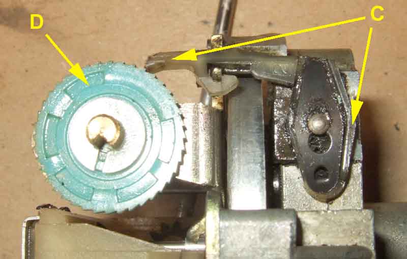
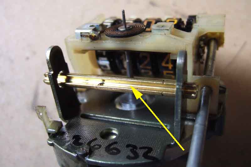
The worm gear is on a shaft that goes though the frame to the pawl C:
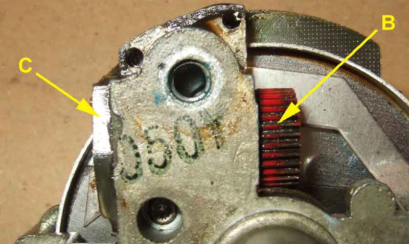
The worm gear shaft has an offset pin which engages with the pawl C. This offset pin and other features means that the pawl is pulled back and pushed forwards once for each full turn of the worm gear, and it is the push that advances the pale blue odo gear (D) one tooth, i.e. for one full turn of the worm gear. In this picture the pawl is fully retracted and about to start advancing the odo gear:
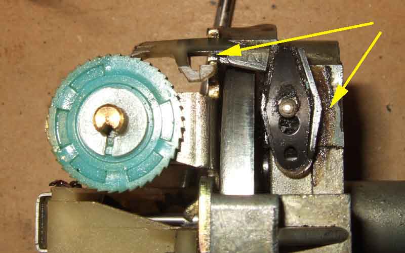
In this picture the pawl is fully advanced and has advanced the odo gear one tooth - note the changes in position at the two arrows compared to when fully retracted above:
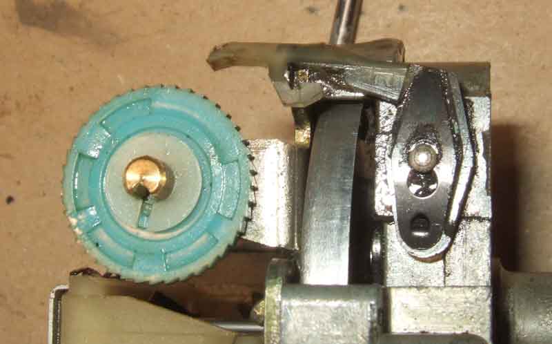
In this picture the cable has turned backwards as when the car reverses, and the pawl is lifted completely clear of the odo gear. When the car is reversing the pawl goes back and fore just the same, but because it has lifted off the odo gear the mileage reading will not change (contrary to what Stephen King would have us believe in 'Christine' where pushing a car backwards made the mileage reduce and reversed the ravages of time and miles ...):
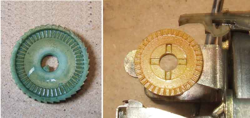
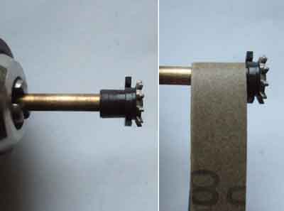
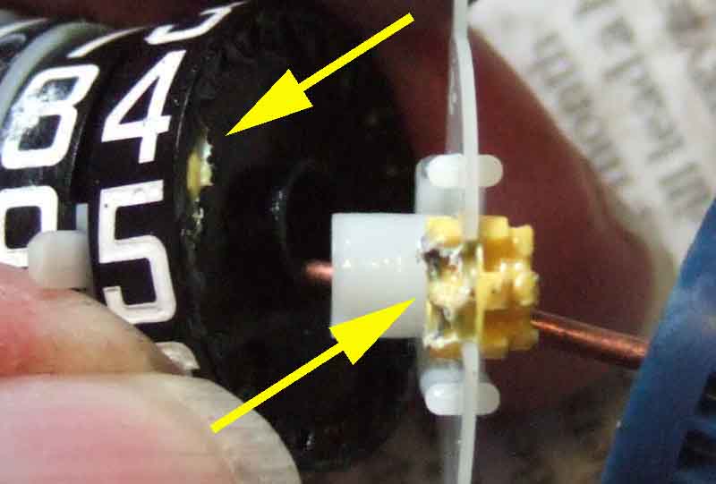
Under the pale blue odo gear is a yellow component that is keyed to the frame. The facing sides have a series of radial ribs and a 3-legged spring pushes these ribs lightly together so that vibration alone cannot move the odo gear, but the pawl has no difficulty pushing the ribs in the odo gear past those on the yellow component:
 The odo gear (B here) is keyed onto the main odo shaft, which goes freely through all the wheels, and is also keyed into the gear (D) at the opposite end. 'A' is the pawl and 'C' the yellow component.
 The number of teeth on the odo gear determine how many fore and aft movements of the pawl are required to turn the odo gear one full revolution i.e. advance the reading by one mile. That causes a variation in the size of the odo gear, but because the pawl has a wide range of vertical positions it can cope with any size of gear. It is the odo gear size plus the number of teeth on the worm gear that control how many turns of the speedo cable are needed to register one mile. This speedo for example takes 1280 turns to advance the odos one mile.
For each full turn of the odo gear, the gear at the other end of the main odo turns once, and this advances the units wheel of the main odo by one digit i.e. one mile. At the same time movement of the black gear goes via an intermediate gear and turns the tenths wheel of the trip odo via another black gear, which moves that one full turn for each turn of the main odo gear and black gears i.e. also one mile. The black gear on the trip odo has a similar friction arrangement to the tenths wheel as that between the blue and yellow parts of the main odo, which means in the normal course of events movement is transmitted from the gear to the tenths wheel of the trip odo.
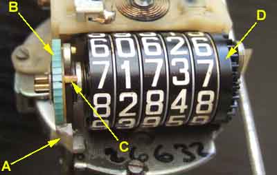
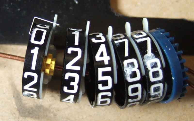
 As to how movement is transmitted from one wheel to the next, it's much easier to look at the trip odo as the gears on that are external. Incidentally, it is because the gears are internal on the main odo that makes it so hard to alter the reading, far harder than modern electronic odometers! Each wheel, on the side adjacent to the succeeding wheel (the 'up' side), has a single slot in its edge (A). This slot passes under the gear when the wheel changes from 9 back to 0 and advances the next wheel. At all other positions the only way the gear and the wheel fit together, is when one of the missing teeth (C) on a gear is facing the edge of the preceding wheel. The other side of the gear has teeth all the way round (D), as does the mating face of the next wheel up in the sequence (B). This means that each wheel turns independently of the next gear up except when it is changing from 9 back to 0, and it always moves in unison with the next wheel down when that is changing from 9 back to 0.
As the lowest wheel turns, a spring is pushing them all together, and friction is trying to turn all the wheels together, and each wheel is trying to turn its preceding gear. But because the 'up' side of each wheel only has one tooth slot in its circumference, the next gear up cannot turn, hence the next wheel up cannot turn. It is only when the digits are changing from 9 back to 0 that the single tooth slot on the 'up' side of a wheel comes round to the next gear up. The friction that is trying to turn all the wheels and gears pushes the next full gear tooth into the slot, and as the slot moves under the gear the gear turns two teeth, which advances the next wheel up by one digit. By that time the slot in the preceding wheel has passed, so the next missing tooth on the gear wheel rides on the outside of the wheel, until 9 comes round again.
 Both main and trip odos operate in the same way, but the trip has the additional complication of being resettable. This also has a keyed shaft, turned by the reset shaft that protrudes from the bottom of the dash. Each odo wheel consists of two parts - the outer with the digits, and an inner. It is the inner that is keyed to the shaft, and that rotates freely inside the outer.
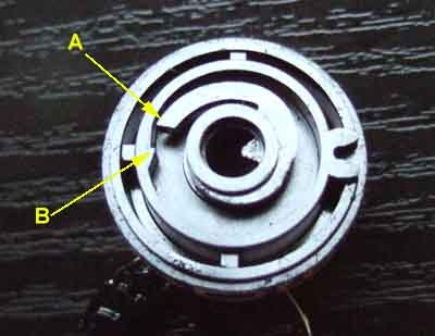 The inner has a finger (A) that lies inside the outer, which has a protrusion (B) at one point, and these two act as a ratchet. As the outers turn (anti-clockwise in this image) with increasing miles, this protrusion flicks past the end of the finger. But when the reset spindle is turned, all the inners turn together, again anti-clockwise relative to the outers. So now as the finger on each inner reaches the protrusion on its outer, it locks against the protrusion, and turns its outer at the same rate. Eventually all the fingers have locked against the protrusions, and all the outers are turning together. This goes against what is described above for normal movement, but under reset conditions the wheels are forced round which pushes the gears out of the way, lifting the pin up against the lever springs. At this time all the digits should be in line, and one keeps turning the reset spindle until all zeros are shown in the slot in the dial.
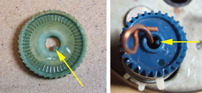
 When zeros are displayed in the dial aperture a pawl (A) on the frame drops into a slot (B) on the disc (shown here above its normal position) adjacent to the hundreds wheel which is also keyed to the shaft and rotates during reset. This makes it harder (but not impossible) to turn the wheels any further, which helps the user stop at zero and not wind it past and have to go all the way round again. Note that this disc has the boss protruding more on one side, and that side goes against the frame.
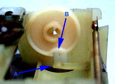
 While the reset shaft is turning the tenths wheel it's driving gear cannot turn as that is locked to the main odo, and the normal friction created by the serrations between the driving gear (A) and the ribs on the tenths wheel (B) is overcome to allow the tenths wheel to turn independently of the black gear.
Everything pictured here fits between the supporting arms on the frame. Adjacent wheels are separated by a (white) gear carrier with a finger (arrowed):
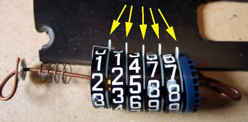
The fingers go in a slot in the frame to keep everything in line, so the digits you see when the speedo is assembled are directly opposite these fingers:
By separating adjacent wheels you can see the drive gear (yellow, only one shown fitted here) that advances each succeeding wheel by one digit for each full rotation of the preceding wheel. Separated like this each gear can be turned to the desired position independently of the wheels either side:
A slotted spindle passes freely through all the components between the support arms except for the gear at the units end:
Both the odo gear (pale blue, left) which sits outside the support arm on the left of the frame and the dark blue gear have a notch that engages in the slot on the spindle:
Note that the pale blue odo gear is a critical component in the calibration of the odometer and if changing components between speedos with different TPMs this component must stay with the speedo to retain the calibration. This is only one of two components that control the mileage calibration, the other is the worm gear that is turned by the worm screw on the speedo input shaft.
The odo gear turns the spindle and that turns the dark blue gear. For every full turn of the odo gear the dark blue gear also makes one full turn, which advances the main odo units wheel by one step i.e. one mile, and through an intermediate gear advances the tenths wheel on the trip odometer one full turn which is also one mile.
 Fully separated there are no less than 25 components! Each position consists of the numbered wheel (A), a gear (C) which fits between adjacent wheels, and a carrier (B) to hold the gear in position. Incidentally the carrier can be either metal on earlier odos e.g. 68 to 73 MGB A suffix, or plastic on later e.g. 74 MGB BS suffix. Each wheel has a cavity both sides, the side facing the preceding wheel has teeth all the way round, and the side facing the succeeding wheel is smooth all the way round except for one position where it will accept a tooth, similar to the trip odo. As in the trip odo the gear has to be fitted the right way round so that the 'all tooth' side goes into the succeeding wheel, but in such a position that when any digit is square in the aperture in the dial, one of the missing teeth is facing the edge of the preceding wheel. It is only like this that the preceding wheel will fit over the gear. On the 'all teeth' side there are two teeth per digit, so it's also possible to get a wheel showing half one digit and half the next through the aperture in the dial - obviously incorrect.
To reassemble from fully dismantled it is 'simply' a matter of sliding each wheel and each gear carrier onto a shaft one at a time, with the gear slot uppermost to prevent the gear falling out, installing the gear in the carrier the right way round, with a missing tooth facing upwards, the digit in the correct position i.e. not half and half, and the fingers on the carriers all pointing in the same direction!
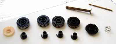
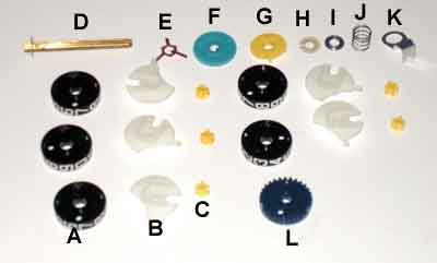
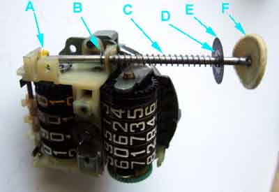
It took me several goes getting each wheel, carrier and gear correctly aligned. I'd work along the row, only to find that by the end one of the preceding ones had moved out of line somehow. Finally I added the spring locator (K), spring (J), stepped washer (I - with the step facing the spring) and locking clip (H) over the end of the wire, and replaced the shaft with a thin stiff wire, keeping the wheels and black gear pressed together so nothing could slip out of place. I compressed the spring while inserting the whole assembly between the sides of the frame as far as the wire would allow - which is further than the shaft would allow, then withdrew the wire, and carefully pushed the parts further between the frame sides until I could just see the hole through the middle, and reinserted the wire. Between withdrawing and reinserting the wire is the tricky time, as everything could ping out. With the wire back in everything is safely retained, can be eased fully into position ready to withdraw the wire and reinsert the shaft. The shaft has a keyway but it only engages with the pale blue odo gear outside the support arms, and the dark blue gear inside the support arms at the opposite end. I'll leave it up to you as to whether you fit the outer locking clip (shown already fitted to shaft D), 3-legged spring (E), odo gear (F) and yellow component (G) to the shaft first then insert that from the pawl end as I did, or the other way round fitting them last. G has fingers that locate to the sides of the support arms that end to prevent it turning, and has radial ribs which interface with similar ribs on the odo gear. The three legged spring presses the two sets of ribs together to prevents the odo gear from turning backwards under light pressure as the pawl retracts. When the pawl advances to turn the odo gear it is forced over the ribs by compressing the three-legged spring. L is the dark blue gear that advances the main odo units wheel one step i.e. one mile for each rotation, and the trip odo tenths wheel by one full rotation i.e. also one mile.
The final step is to get the fingers in the gear carriers in the slot in the frame. The later plastic ones will probably be easier in this respect as they are flexible, with the metal ones you will have to locate them before the shaft is fully in position. Note that the spring locator (K) fits round behind the 10k wheel and over the finger on that gear carrier. This centralises that end of the spring (which keeps everything pressed together between the support arms), with the stepped washer centralising the other end.
It was only when I'd done that, that I realised I'd set the mileage exactly, when really I needed to set it back a few miles, and turn it manually to check all was well before putting it back in the case and in the car. A pal had the lateral idea of driving the car with the old speedo for a few more miles, then turning the new one on manually to match. But given the salt on the roads impatience got the better of me, so I took it apart again! I wanted to achieve 60515, which was relatively convenient as I could set it to 60498 or so, then I'd only have to wind it forwards 17 miles, and could at least check the first three wheels. As it can only be put back together with the gears in the right place, and as long as I ended up with all digits in line, the others should be fine. So that was done, and by turning the odo gear by hand rather than relying on the pawl I was able to advance it pretty quickly, and all was well with both main and trip odos.
What was wrong with Bee's odometer?
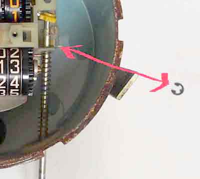
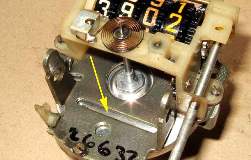
 With the innards out of the case almost immediately I could see exactly what was wrong - the pawl and gear that advances the mileage one step at a time weren't engaged. The gear (A) was way out of line with the pawl (B), because the shaft on which it sits was partially withdrawn. I pushed it back which got everything working again, but very little pressure was needed to push it out again, so I had no confidence they would stay engaged. There are two split plastic locking clips (C and E) sitting in grooves in the shaft, each side of the frame. The outer one was very firm, but the inner one came out of its groove (D) all too easily. Could be the clip, or the shaft, but I didn't feel like sending off for bits yet. I reckoned if I could fashion a clip that hooked onto the frame and pressed lightly on the end of the errant shaft, that would hold it in place.
 At first I thought about a springy strip, but settled for spring wire, and half an hour or so of careful tweaking seemed to do the job, and driving with a drill sent the wheels merrily round.
Flushed with success, and with no prospect of taking Bee out for an extended test of the odometers now we have salt on the roads, curiosity got the better of me in terms of wanting to find out what was wrong with Bee's trip. Using the slot I had cut previously I got the mechanism out quite easily, with pointer and dial in place. That allowed me to remove the pointer by turning the cup to 60 mph and twisting and pulling as with the 'new' speedo, and remove the dial.
 Remove the felt washer (F), copper washer (E), steel washer (D) and spring (C) from the reset spindle. Remove the circlip (B) from the spindle just above where it goes through the lower part of the frame without losing it. Slide the shaft down and out of the yellow plastic gear (A), which will fall free.
 Remove the gears (C) and pin (A) they turn on by lifting the pin up against pressure from the lever springs (B) above it and pulling forwards. Note that the left-hand spring sits in a thinner section of the pin to locate it. Take the gears off and refit the pin to hold the springs away from the wheels. Withdraw the shaft from the reset spindle end. Ease the wheels forwards together with spring (D) at the tenths end, and the white disc (E) from the hundreds end, and out of the frame, being careful not to damage the pointer hair spring - you may have to lift the pin up a little to do this - or lose the coil spring.
With the wheels separated you will see the inner part with the finger inside each of them. Insert the shaft into a wheel, lining up the keyway. Turn the shaft and the inner part should rotate very easily inside the outer part, at least until the reset finger locks against the protrusion. Test each of the wheels this way, and this is when I think I discovered the problem with Bee's trip.
The tenths wheel was very free, the hundreds a little stiff, but the units and tens were both quite stiff. As the problem usually occurred when changing a units or tens, I reckon the stiffness was preventing those wheels from trying to turn with the normal friction between the wheels, which was preventing the gear from going into the single slot in the tenths wheel and so moving the succeeding wheel. As to why it was stiff, I had noticed oil around the hair spring, and between the two parts of each trip wheel where one rotates inside the other. So is it possible the oil has caused the plastic to swell in some way? The white digits particularly on the trip odo are also discoloured to varying degrees, could that be from oil?
As to why oil should be so visible, many years ago I had a flicking pointer, but rather than the rapid flicking that indicates a problem with the cable it was only occurring as the tenths wheel on the trip odo moved. Taking the speedo out of the dash and testing the input shaft it did feel stiff, so I put a drop of oil on it, which freed it up, and after that the pointer was steady. Now people do say that too much grease in the cable can work its way up into the speedo and clog the works. But I did only use a drop of light machine oil, and looking at the back of the spinning magnet and cup there is no oil there, or on the frame round it, so I don't really understand how it could have appeared on the trip wheels from that source. And to be fair the odo digits have always been stained to some extent.
 Cleaning the oil from the two halves of each wheel made no difference - not even making them stiffer. I pondered how I might free them up a bit, and eventually settled on putting each inner in turn on the shaft, where it is keyed, then putting the shaft in my drill-driver. A strip of fine wet-and-dry folded round the boss that fits inside the outer, and a few moments running the drill was making them freer. After that it was just a matter of reassembling and testing. Rather than running the input shaft from a drill it's much easier to use one of the black gears on either the main or trip odos as a thumbwheel which advances things much faster, slowing down as the tens (in my case) was about to advance to see if there is any tendency to stick, and after a couple of hundred 'miles' all seemed well, but of course by this time I had the replacement fitted to Bee, which has also worked well.
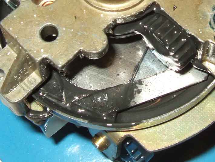
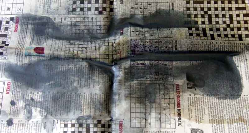
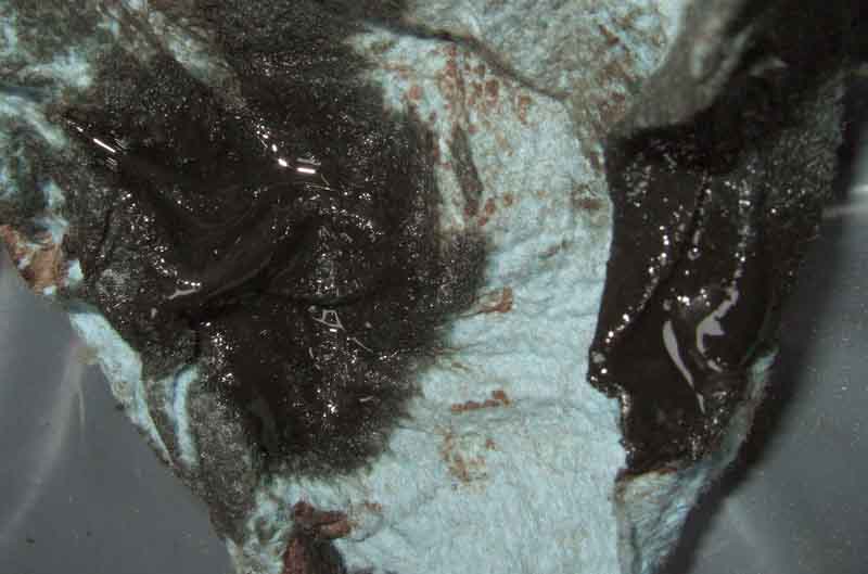
I sprayed the back of the mechanism with variously brake cleaner and the more powerful blast from carb cleaner (don't use carb cleaner near plastics!), holding the mechanism at an angle, to keep the fluid away from the dial and the numbers as much as possible - only partly successful as it turned out, as in the end some of the digits got smudged purely from the fluid, not from rubbing with anything. Done over newspaper copious staining resulted, and several goes were needed to wash all the black oil out by moving the needle cup round manually to various positions:
That left the cleaning fluid bridging the gap mentioned above, and even that was enough to drag the cup round more than it should be. Vigorous shaking got some out, I tried a hot air gun - at a distance! but a blower nozzle on my compressor was probably the most effective, that and leaving out in the sun for a while I attacked the cable.
I was amazed to find the cable inner completely coated in oil, which stayed liquid on the blue hand-wipe paper I used to wipe it off:
And even after that when coiled up and placed on cardboard significant amounts were transferred and several more full-length wipes with clean paper were needed:
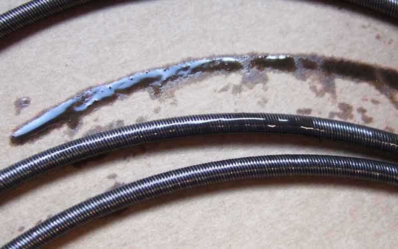
That left the outer, so I refitted the inner and pulled it out again wiping as I went depositing more on clean areas of the cloth, repeated several times. This oil was jet black and showed none of the strong sulphur smell that the oil I've used in the gearbox has, so I don't see it having come up from the gearbox, nor would I have put that much on the inner before fitting the new cable, and I don't recall doing that at all. It reminded me of the 'Oildag' we used many decades ago on electromechanical switching equipment, which is a suspension of fine graphite powder in oil. The original cable that had been in for about 150 miles since the gearbox rebuild until it broke shows no signs of it, this new cable only having done about 300 miles. Even the incorrect cable Leacy sent me originally has nothing like that - what ever it is clear and more like Vaseline than lubricating oil. It's a mystery. It was interesting to note that rotating the inner when not quite engaged with the drive gear at the gearbox was very much easier than pushing and pulling the inner in and out.
Replacement was the reverse - except for clamping it back into the dash - as in a few miles I want to remove the inner to see if there are signs of it happening again. If not clamp it in and leave it longer before checking again, and if all looks OK send it off to JDO Instruments to get the number wheels replaced. They advertise a 48-hour turn-round for Ł100 plus Ł5 for mileage correction plus Ł9.95 P&P plus Ł5 for Ł500 insurance. New replacements from Rimmer are Ł200 plus P&P and of course you lose your mileage reading.
However! Whilst the speed indication was correct the odometer had stopped working. So out again, and much close examination and poking including rigging up to a drill to discover the cause. The odometer actuator was going back and fore, but it wasn't turning the cogs. Both the trip and main odo wheels seem to be free so it looked like the idler cog between the two was jammed. That is just visible through the mechanism, and poking with a fine probe showed that was free as well. So nothing for it but to remove the main odo cluster. Each wheel has the black number ring, a yellow cog that turns the wheel one step for each revolution of the preceding wheel, and a white cog carrier, and the yellow cogs were stuck to the black wheels. Took a bit of force to lever them apart, and it was obvious that the cogs had partially melted and glued themselves to the wheel. I'd used brake cleaner and carb cleaner to wash out the speed indication part, and testing the old cogs in a little of each it was obvious that it was the carb cleaner that was doing the damage. Brake cleaner seemed to be fine, and evaporated very quickly as well:
So the moral of the story is, if you get oil in your speedo it's probably not worth trying to clean it out. Make sure you have fixed the root cause, then send it off for repair! Even though it had only done a dozen miles since cleaning the cable inner while the speedo was out again I took the inner out again, and there did seem to be oil at the bottom, and this time it smell like gearbox oil. So cleaned it off again and put it back (again speedo only temporarily) to give it a longer test, and in the meantime investigate speedo drive pinion seals.